
Fusion FWD V6-3.0L (2009)
Removal and Installation
NOTICE: Suspension fasteners are critical parts because they affect performance of vital components and systems and their failure may result
in major service expense. New parts must be installed with the same part numbers or equivalent part, if replacement is necessary. Do not use a
replacement part of lesser quality or substitute design. Torque values must be used as specified during reassembly to make sure of correct
retention of these parts.
All vehicles
1. Remove the wheel and tire.
Front Wheel Drive (FWD) vehicles
2. Remove the toe link shield bolt.
-
To install, tighten to 8 Nm (71 lb-in).
3. Remove the pushpin and the shield.
All vehicles
4. Remove and discard the toe link inboard nut and bolt.
-
To install, tighten the new nut to 110 Nm (81 lb-ft) with the suspension at the bushing fastener tightening position.
All-Wheel Drive (AWD) vehicles
5. Remove and discard the toe link outboard nut and bolt and remove the toe link.
-
To install, tighten the new nut to 90 Nm (66 lb-ft) with the suspension at the bushing fastener tightening position.
FWD vehicles
6. Remove the toe link outboard bolt and remove the toe link.
-
To install, tighten the new bolt to 110 Nm (81 lb-ft) with the suspension at the bushing fastener tightening position.
All vehicles
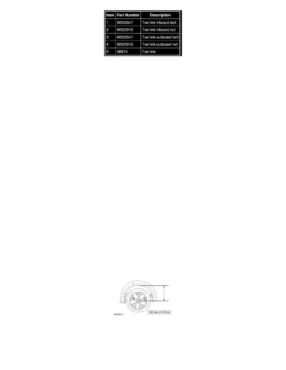
7. NOTICE: Before tightening any suspension bushing fasteners, the suspension must be at the bushing fastener tightening position. Use a
suitable jack to raise the suspension until the distance between the center of the hub and the lip of the fender is equal to 395 mm (15.55
in). This will prevent incorrect clamp load and bushing damage.
To install, reverse the removal procedure.
8. Check and, if necessary, adjust the rear toe.