
Fusion FWD V6-3.5L (2010)
-
Is the resistance less than 5 ohms?
Yes
GO to AC31.
No
CONNECT the negative battery cable. GO to AC67.
-------------------------------------------------
AC31 CHECK THE MS-CAN (+) AND MS-CAN (-) CIRCUITS FOR A SHORT TOGETHER WITH THE SOD-R DISCONNECTED
-
Disconnect: Side Obstacle Detection Control Module - Right (SOD-R) C4229 .
-
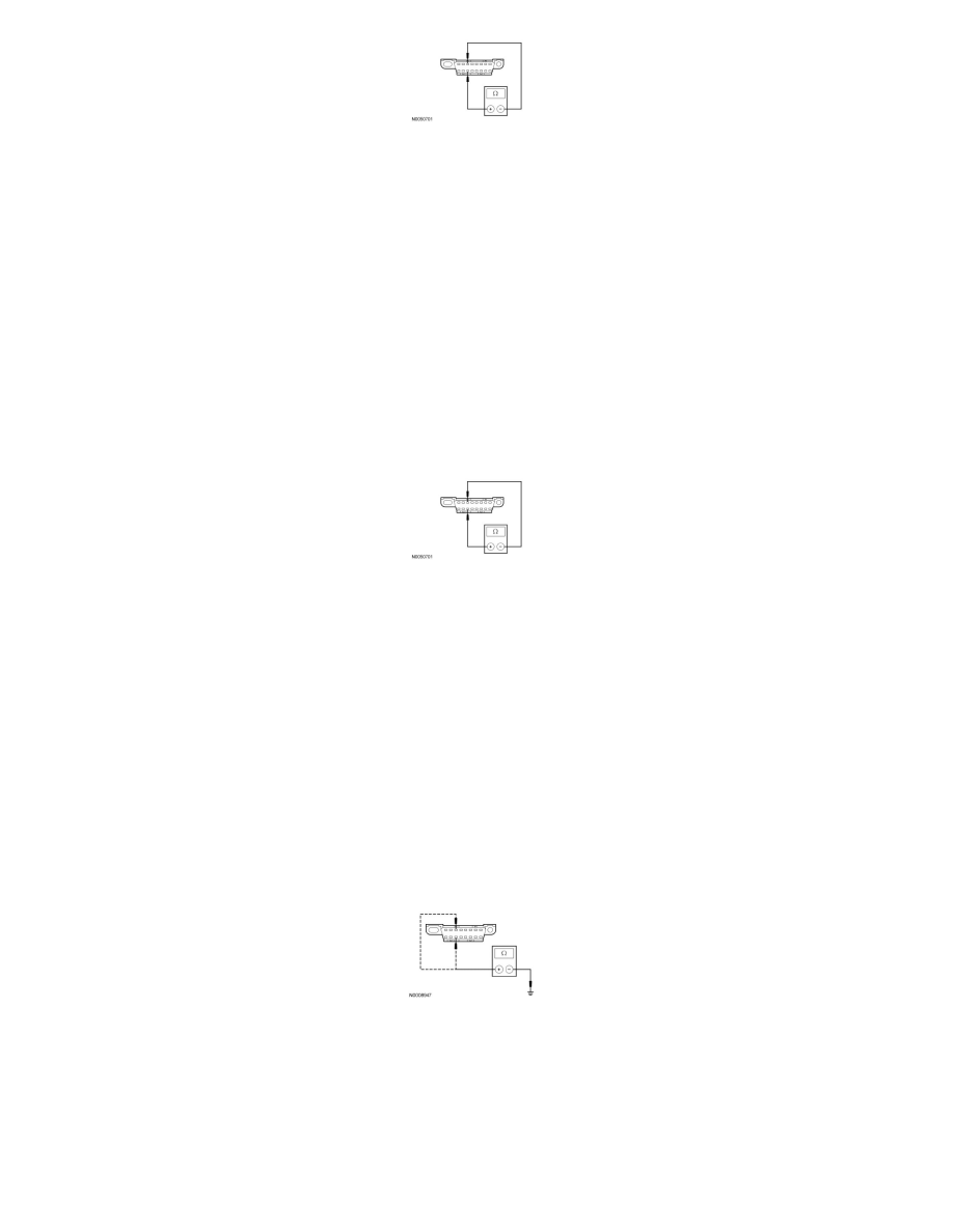
Measure the resistance between the DLC C251-3, circuit VDB06 (GY/OG), harness side and the DLC C251-11, circuit VDB07 (VT/OG), harness
side.
-
Is the resistance less than 5 ohms?
Yes
REPAIR the circuit. CONNECT all modules. CONNECT the negative battery cable. CLEAR the DTCs. REPEAT the network test with the scan tool.
No
CONNECT the negative battery cable. GO to AC68.
-------------------------------------------------
AC32 CHECK THE MS-CAN (+) AND MS-CAN (-) CIRCUITS FOR A SHORT TO GROUND WITH THE SJB DISCONNECTED
-
Disconnect: SJB C2280b .
-
Measure the resistance between the DLC C251-3, circuit VDB06 (GY/OG), harness side and ground; and between the DLC C251-11, circuit
VDB07 (VT/OG), harness side and ground.
-
Are the resistances greater than 1,000 ohms?
Yes
CONNECT the negative battery cable. GO to AC53.
No
If the vehicle is equipped with a Parking Aid Module (PAM), GO to AC33.