| Disassembly Special Tool(s) | | Flange Holding Wrench, Universal 205-072 (15-030A) | | | Locking Tool, Flywheel 303-254 (21-135) | | | Socket, Cylinder Head Bolt 303-392 (21-167) | | | Remover/Installer, Hose Clamp 303-397 (24-003) | | | Mounting Stand 303-435 (21-187) | | | Mounting Bracket for 303-435 303-435-04 (21-031B) | | | Mounting Plate for 303-435 303-435-12 (21-150A) | | | Remover, Vibration Damper Hub 303-509 (21-213) | General Equipment Oil filter strap wrench Engine hoist One bolt M6 x 60 mm Two bolts M8 x 30 mm Three bolts M8 x 25 mm Materials Name Specification High temperature grease ESD-M1C220-A Disassembly | | -
Remove the intermediate shaft center bearing bracket. | | | -
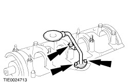
Using a suitable oil filter strap wrench, remove the oil filter. | | | -
Disconnect the oil pressure switch electrical connector. | | | -
Install the special tool. | | | -
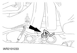
Disconnect the crankshaft position (CKP) sensor electrical connector. | | | -
Install the special tool. | | | -
Mount the engine on the mounting stand. | | | -
Drain the engine. - Allow the oil to drain into a suitable container.
- Discard the drain plug washer.
| | | -
NOTE:Install a new oil drain plug washer. Install the oil drain plug. | | | -
Disconnect the camshaft position (CMP) sensor electrical connector. | | | -
Disconnect the engine cooling fan temperature switch and engine coolant temperature sender unit electrical connectors. | | | -
Disconnect the ignition coil electrical connectors. | | | -
Detach the generator wiring harness support guide from the cylinder head. | | | -
Disconnect the throttle position (TP) sensor electrical connector. | | | -
Disconnect the idle air control (IAC) valve electrical connector. | | | -
Disconnect the power supply rail from the fuel injectors. | | | -
Remove the engine rear lifting eye. | | | -
Remove the ignition coil and spark plug wires. | | | -
Remove the engine support plate bracket and the generator bracket from the cylinder head. | | | -
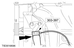
Using the special tool, disconnect the coolant hose from the water pump. | | | -
Remove the exhaust manifold heat shield. | | | -
Remove the oil level indicator and tube. | | | -
NOTE:Pull back the accessory drive belt tensioner. Remove the power steering pump and generator bracket. | | | -
Remove the exhaust manifold. - Discard the gaskets and retaining nuts.
| | | -
Remove the positive crankcase ventilation (PCV) tube. | | | -
Remove the coolant outlet housing. | | | -
Detach the throttle body bracket from the throttle body. | | | -
Remove the throttle body. | | | -
Remove the intake manifold. | | | -
Remove the engine support plate bracket and the engine front lifting eye. | | | -
Remove the water pump pulley. | | | -
Remove the engine support plate. | | | -
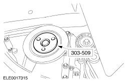
Remove the crankshaft pulley retaining bolt and remove the crankshaft pulley. - Discard the retaining bolt.
| | | -
Remove the engine upper front cover. | | | -
NOTE:Only turn the crankshaft in the normal direction of rotation. Turn the crankshaft to top dead center (TDC). | | | -
Remove the timing chain upper guide. | | | -
Using the special tool, remove the camshaft sprockets. | | | -
CAUTION:Prevent the timing chain tensioner pivot bolt retaining washer from dropping into the timing case. Remove the timing chain tensioner arm. - Remove the retaining washer.
- Using a M6 x 60 mm bolt, remove the timing chain tensioner pivot bolt.
| | | -
Remove the timing chain tensioner. - Discard the timing chain tensioner.
| | | -
Remove the engine front cover. - Discard the engine front cover.
| | | -
Remove the oil pump chain. - Remove the chain tensioner.
- Remove the oil pump sprocket and chain.
| | | -
Remove the timing chain guide lower retaining bolt. | | | -
Remove the timing chain guide upper retaining bolt. | | | -
Remove the timing chain and the timing chain guide. | | | -
Remove the camshafts. - Remove the timing chain upper guide bracket.
- Remove the camshaft bearing caps.
| | | -
CAUTION:Do not remove the cylinder head bolts until the cylinder head has cooled to below 30°C. Remove the front three cylinder head bolts. | | | -
CAUTION:Remove the cylinder head bolts in the sequence shown. Using the special tool, remove the cylinder head. | | | -
Remove the clutch disc and pressure plate. For additional information, refer to Section 308-01 Clutch. | | | -
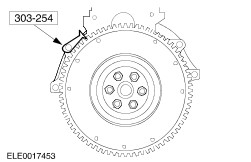
Using the special tool, lock the flywheel in position. | | | -
Remove the oil pressure switch. | | | -
Remove the crankshaft position (CKP) sensor. | | | -
Remove the oil pump pick-up tube. | | | -
Remove the crankshaft rear oil seal carrier. | | | -
Using a suitable press remove the oil seal on a flat surface. | | | -
NOTE:Keep the connecting rod bearing caps and bearing shells in order for installation. Remove the connecting rod bearing caps. | | | -
NOTE:Keep the crankshaft bearing caps, bearing shells and thrust half-washers in order for installation. Remove the crankshaft main bearing caps. | | |