| Removal Special Tool(s) | | Remover/Installer, Hose Clamp 303-397 (24-003) | | | Socket, Flywheel Bolt 303-502 (21-205) | General Equipment Trolley jack Workshop table Engine hoist Retaining straps | | -
WARNING:Do not smoke or carry lighted tobacco or open flame of any type when working on or near any fuel related components. Highly flammable mixtures are always present and may ignite. Failure to follow these instructions may result in personal injury. | | | -
Disconnect the positive cable from the battery terminal clamp. | | | -
Disconnect the electrical connectors. - Disconnect the engine wiring harness electrical connector.
- Disconnect the engine coolant level sensor electrical connector.
| | | -
Remove the battery side cover. - Detach the cooling system degas hose from the battery side cover.
- Detach the engine wiring harness electrical connectors from the retaining bracket.
| | | -
Remove the battery tray. - Detach the wiring harness rail from the battery tray.
- Detach the coolant hose from the battery tray.
| | | -
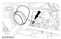
Remove the air cleaner outlet pipe. | | | -
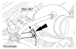
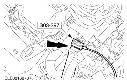
Using the special tool, disconnect the coolant hose from the expansion tank. | | | -
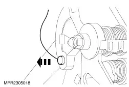
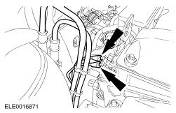
Disconnect the accelerator cable from the throttle body. | | | -
Detach the accelerator cable bracket from the throttle body and position it to one side. | | | -
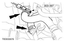
Using the special tool, disconnect the coolant hoses from the coolant pipes. | | | -
Using the special tool, disconnect the coolant hose from the transaxle oil cooler and disconnect the turbine shaft speed (TSS) sensor electrical connector. | | | -
Using the special tool, disconnect the coolant hose from the coolant outlet housing. | | | -
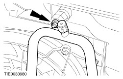
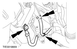
Disconnect the selector cables from the transaxle shift levers. - Unclip the selector cable.
- Detach the selector cable from the bracket.
| | | -
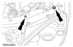
Disconnect the vacuum hoses from the intake manifold. - Disconnect the brake booster vacuum hose.
- Disconnect the vacuum hose.
| | | -
Using the special tool, disconnect the coolant hose. | | | -
Disconnect the generator positive cable from the battery junction box (BJB). | | | -
Disconnect the generator electrical connectors. | | | -
Detach the refrigerant line support bracket from the opening panel. | | | -
Using the special tool, disconnect the coolant hose from the coolant distribution tube. | | | -
Using the special tool, disconnect the coolant hoses from the coolant pipes. | | | -
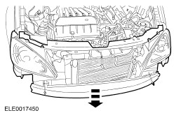
Remove the front bumper. For additional information, refer to Section 501-19 Bumpers. | | | -
Fabricate two M10 x 250 mm guide bars out of a suitable threaded bar. | | | -
Detach the radiator grille opening panel reinforcement from the fender apron panels on both sides. | | | -
Loosen the radiator grille opening panel. - Remove the front bumper bracket upper retaining bolts and screw in the guide bar about 40 mm on both sides.
- Remove the front bumper bracket lower retaining bolts on both sides.
| | | -
Pull the radiator grille opening panel to the front as far as possible. | | | -
Disconnect the starter motor ground cable and detach the generator positive cable from the bracket and from the side member. | | | -
CAUTION:Use an Allen key to prevent the power steering pump pulley from rotating. Remove the power steering pump pulley. | | | -
Detach the power steering line bracket from the cylinder block. | | | -
Detach the power steering pump from the engine and secure it to one side. | | | -
Detach the A/C compressor from the A/C compressor bracket and secure it to one side. - Disconnect the A/C compressor clutch electrical connector.
- Detach the power steering line bracket from the A/C compressor bracket.
- Remove the A/C compressor retaining bolts.
| | | -
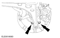
Detach the lower arm from the wheel knuckle on both sides. | | | -
CAUTION:Secure the halfshaft to prevent damage to the CV joints. The inner CV joint must not be bent more than 20 degrees. The outer CV joint must not be bent more than 50 degrees. CAUTION:Do not damage the halfshaft seal. NOTE:Cap the transaxle to prevent oil loss or dirt ingress. Detach the right-hand halfshaft and the intermediate shaft from the transaxle and secure them to one side. - Discard the bearing locknuts.
- Allow the oil to drain into a suitable container.
| | | -
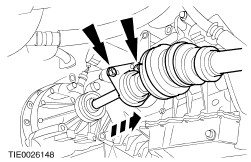
CAUTION:Secure the halfshaft to prevent damage to the CV joints. The inner CV joint must not be bent more than 20 degrees. The outer CV joint must not be bent more than 50 degrees. Using the special tool, detach the left-hand halfshaft from the transaxle and secure it to one side. | | | -
Detach the transaxle wiring harness. - Disconnect the solenoid valve control unit electrical connector.
- Disconnect the output shaft speed sensor (OSS) electrical connector.
- Disconnect the transmission range (TR) sensor electrical connector.
| | | -
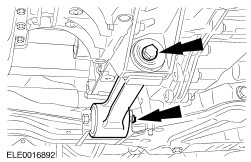
Remove the engine support insulator. | | | -
CAUTION:Use suitable retaining straps to secure the engine and transaxle assembly on the workshop table. Using suitable wooden blocks, position the engine and transaxle assembly on the workshop table. | | | -
Remove the engine rear mount. - Remove the bolt.
- Remove and discard the bolts and the nut.
| | | -
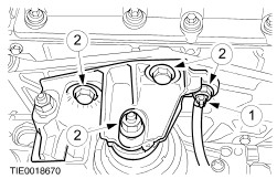
Remove the engine front mount. - Disconnect the ground cable from the engine front mount bracket.
- Remove the nuts and bolts.
| | | -
Raise the vehicle, remove the engine and transaxle assembly. | | | -
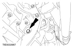
Detach the coolant pipe from the transaxle. | | | -
Disconnect the starter motor electrical connector. | | | -
Disconnect the vehicle speed sensor (VSS) electrical connector. | | | -
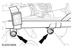
Detach the torque converter from the drive plate (three nuts). | | | -
Using a suitable engine hoist support the engine and remove the transaxle lower and right-hand retaining bolts. | | | -
Remove the transaxle left-hand retaining bolts. | | | -
WARNING:Make sure the torque converter remains in the torque converter housing. Remove the transaxle from the engine. | | |