| Assembly Special Tool(s) | | Installer, Front Hub Bearing Cup/Oil Seal 204-087 (14-029) | | | Installer, Halfshaft Oil Seal 204-175 (14-050) | | | Installer, Driveshaft Oil Seal 205-051 (15-015) | | | Adapter for 205-071 205-071-01 (15-026A-01) | | | Installer, Differential Bearing Cone 205-073 (15-034) | | | Installer, Rear Hub Oil Seal 205-075 (15-036) | | | Socket, Steering Gear Plug 211-136 (13-012) | | | Compressor, Valve Spring 303-060 (21-024) | | | Adapter for 303-060 303-060-02 (21-024-02) | | | Adapter for 303-060 303-060-07 (21-024-07) | | | Aligner, Clutch Plate 303–173 (21-103-A) | | | Installer, Crankshaft Oil Seal 303-395 (21-171) | | | Mounting Stand 303-435 (21-187) | | | Mounting Bracket for 303-435 303-435-06 (21-031B) | | | Compressor, Clutch Spring 307-015 (17-058) | | | Installer, Oil Pump Oil Seal 307-032 (17-010A) | | | Gauge Bar, Shim Selection 307-300 (17-055) | | | Installer, Halfshaft Output Oil Seal 307-157 (17-071) | | | Compressor, Spring Washer 307-209 (17-040) | | | Depth Gauge, Shim Selection 307-300-02 (17-055-02) | | | Guide Sleeve, One-Way Clutch 307-327 (17-074) | | | Measuring Fixture, Second/Third Gear Brake 307-389 (17-077) | | | Socket, Guide Sleeve 308-109 (16-040A) | | | Installer, Differential Double Lip Oil Seal 308-203 (16-066) | General Equipment Dial indicator gauge Hot air gun Depth gauge Feeler gauge Press Materials Name Specification Automatic transmission fluid N052162 VX00 Loctite AMV 185 101 A1 Sealing compound AKD 456 000 01 Sealing compound AMV 188 200 Petroleum jelly Assembly CAUTION:Do not use automatic transmission fluid of any other specification as this may result in failure of the transmission. NOTE:All taper roller bearings on the same shaft should be renewed. NOTE:Lubricate all parts and sealing rings with automatic transmission fluid. NOTE:Compress any clutch whose axial play is to be measured, so that the automatic transmission fluid is pressed out. NOTE:Install new gaskets, oil seals, O-rings, circlips, self-locking nuts, compression springs and transaxle fluid pump retaining bolts. NOTE:Immerse new friction plates in clean automatic transmission fluid for 15 minutes prior to installation. | | -
Using a suitable press and the special tool, install the output shaft needle roller bearing. | | | -
Heat the taper roller bearing to 80-100 °C before installing. | | | -
CAUTION:Use a thick cloth to prevent the possibility of scalding. Using a suitable press and tube, install the output shaft taper roller bearing. | | | -
Install the output shaft. | | | -
NOTE:Install a new output shaft bearing housing oil seal. Using the special tool, install the output shaft bearing housing oil seal. | | | -
NOTE:Install a new output shaft bearing housing O-ring. Install the output shaft bearing housing O-ring. | | | -
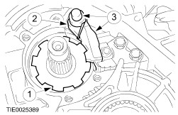
Using the special tool, install the output shaft bearing housing. | | | -
NOTE:Install the securing bolt within 5 minutes of applying the sealing compound. Install the securing bolt. | | | -
NOTE:Install a new selector shaft O-ring. Install the selector shaft O-ring seal. | | | -
Install the selector shaft. | | | -
Install the selector shaft expanding bolt. | | | -
NOTE:The spring on the parking pawl must press the parking pawl away from the parking pawl gear wheel. Install the support plate assembly. | | | -
NOTE:The smooth side of the parking pawl faces downwards. NOTE:The spring on the parking pawl must press the parking pawl away from the parking pawl gear wheel. Install the parking pawl assembly. - Install the parking pawl gear.
- Install the parking pawl.
- Install the spindle, spring, washer and circlip.
| | | -
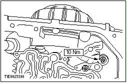
Install the selector shaft lock washer bolt. | | | -
Install the detent spring. | | | -
Using a suitable press and the special tool, install the output shaft bearing cone. | | | -
Install the output shaft bearing cover. | | | -
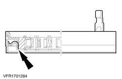
NOTE:Make sure that the mating surfaces of the taper roller bearing and the bearing seat on the output shaft drive gear are clean and oil free. NOTE:Apply a thin film of Loctite to the bearing area output shaft drive gear. NOTE:Install the taper roller bearing within 30 minutes of applying the Loctite. Using a suitable press and the special tool, install the output shaft drive gear taper roller bearing. | | | -
Install two 1.5 mm thick measuring shims on the output shaft. | | | -
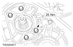
NOTE:Engage the parking lock when tightening the output shaft drive gear retaining nut. Install the output shaft drive gear. | | | -
NOTE:Do not rotate the output shaft during measurement. Measure the output shaft end float. | | | -
Calculate the output shaft adjusting shims required. - To achieve the bearing preload, subtract the measured value (example 0.93 mm), the constant value for compression (0.12 mm) and the set value (0.10 mm) from the measuring shims (2 x 1,5 mm = 3 mm).
- Example: 3.00 mm - 0.93 mm - 0.12 mm - 0.10 mm = 1.85 mm.
- Install an adjusting shim with a thickness of 1.85 mm.
For additional information, refer to Specifications in this section.
| | | -
NOTE:Engage the parking lock when releasing the gear. Remove the output shaft drive gear. | | | -
NOTE:Remove the measuring shims. Install the appropriate shim. | | | -
NOTE:Engage the parking lock when tightening the output shaft retaining nut. Install the output shaft drive gear. | | | -
NOTE:Make sure that the mating surfaces of the bearing cone and the bearing seat on the planetary gear output wheel are clean and oil free. NOTE:Install the taper roller bearing within 30 minutes of applying the Loctite. NOTE:Apply a thin film of Loctite to the bearing seat on the planetary gear output wheel. Using a suitable press and the special tool, install the planetary gear output wheel taper roller bearing. | | | -
NOTE:Make sure that the bearing seats are clean and oil free. NOTE:Install the taper roller bearing within 30 minutes of applying the Loctite. NOTE:Apply a thin film of Loctite to the bearing seat on the planetary gear output wheel. Install the planetary gear output wheel outer taper roller bearing. | | | -
NOTE:Install the planetary gear output wheel without the Belleville washer or the shim. NOTE:Lock the parking lock when tightening planetary gear output wheel tensioning bolt. NOTE:The planetary gear output wheel and the output shaft drive gear can only be renewed as an assembly. Install the planetary gear output wheel. - Install the planetary gear output wheel in the taper roller bearing.
- Using the special tool, tighten the tensioning bolt.
| | | -
Using the special tool, remove the planetary gear output wheel tensioning bolt. | | | -
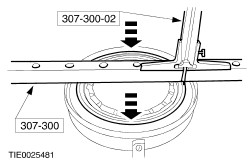
Set the depth gauge to zero. - Position the gauge on the measuring bar (or measuring plate) and slide down the depth gauge as far as possible.
- Zero the gauge.
| | | -
Using the special tool, measure the depth of the planetary gear output wheel outer taper roller bearing. | | | -
Using the special tool, measure the depth of the planetary gear output wheel. | | | -
Calculate the adjusting shim. - To achieve the bearing preload, subtract the constant value (0.18 mm) from the measured value (example X1 – X2) and add the Belleville washer thickness (1.5 mm).
- Example: 20.50 mm - 19.5 mm - 0.18 mm + 1.5 mm = 2.32 mm.
- The adjusting shims are categorised in steps.
For additional information, refer to Specifications in this section.
- Intermediate measured values are rounded up.
- The calculated adjusting shim in the example is between 2.30 and 2.32 mm, therefore the actual adjusting shim to use in the example is 2.325 mm.
| | | -
Install the planetary gear output wheel needle roller thrust bearing. - Install the appropriate shim.
- Install the needle roller bearing.
- Install the Belleville washer.
- Install the tensioning bolt.
| | | -
Using the special tool, tighten the planetary gear output wheel tensioning bolt. | | | -
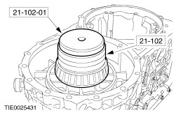
CAUTION:Use a thick cloth to prevent the possibility of scalding. Heat the torque converter housing with the hot air gun before installing. | | | -
NOTE:Install the bearing cone in the torque converter housing without a shim. Using a suitable press and the special tool, install the differential bearing cone. | | | -
Using a suitable press and the special tools, install the differential taper roller bearing. | | | -
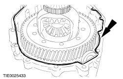
Install the differential assembly. | | | -
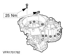
NOTE:Tighten every second bolt. Install the torque converter housing. | | | -
Measure the differential end float. - Move the differential up and down.
- Record the value indicated.
| | | -
Calculate the adjusting shim. - To achieve the bearing preload, add the measurement value (example 0.60 mm), the set value (0.10 mm), and the constant value for compression (0.12 mm).
- Example: 0.60 mm + 0.10 mm + 0.12 mm = 0.82 mm
- Install the adjusting shim with a thickness of 0.82 mm.
For additional information, refer to Specifications in this section.
| | | -
Remove the torque converter housing. | | | -
Using the special tool, remove the differential bearing cone. | | | -
NOTE:Make sure that the mating surfaces of the bearing cone and bearing carrier are clean and oil free. NOTE:Install the bearing cone within 30 minutes of applying the Loctite. NOTE:Apply a thin film of Loctite to the bearing carrier. Using a suitable press and the special tool, install the differential bearing cone. - Install the appropriate shim.
- Install the bearing cone.
| | | -
NOTE:Make sure that the mating surfaces of the transmission and the torque converter housing are clean and oil free. NOTE:Install the torque converter housing within 10 minutes of applying the sealing compound. Apply approximately a 2 mm bead of sealing compound to the inside edge of the transaxle surfaces. | | | -
NOTE:The transmission housing must not be turned before tightening the bolts. Install the torque converter housing. | | | -
Tighten the converter housing bolts and nuts. | | | -
Install the speedometer worm gear assembly. - Install the speedometer worm gear.
- Install the circlip.
- Install the O-ring.
| | | -
Install the right-hand halfshaft oil seal housing. | | | -
Install the speedometer drive pinion. | | | -
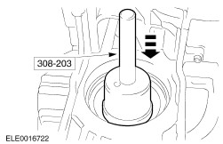
NOTE:Install a new intermediate driveshaft extension oil seal. Using the special tool, install the intermediate driveshaft extension oil seal. | | | -
Using the special tool, install the right-hand halfshaft extension protective cap. | | | -
NOTE:Install a new intermediate shaft extension assembly O-ring. Install the intermediate shaft extension assembly. - Install the snap ring.
- Install the O-ring.
| | | -
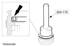
NOTE:Install a new output shaft drive flange O-ring. Using the special tool, install the left-hand output shaft drive flange oil seal. | | | -
NOTE:Install a new left-hand output shaft drive flange snap ring. Install the left-hand output shaft drive flange. | | | -
NOTE:Install a new planetary gear O-ring. Install the planetary gear O-ring. | | | -
NOTE:Insert the needle roller thrust bearing washer smooth side to the planetary gear output wheel. Install the planetary gear assembly. - Install the needle roller thrust bearing washer.
- Install the needle roller thrust bearing.
- Install the needle roller thrust bearing washer.
- Install the O-ring.
- Install the planetary gear.
| | | -
Install the needle roller thrust bearing assembly. - Install the washer.
- Install the thrust bearing.
| | | -
Install the one-way clutch cylindrical pegs. | | | -
NOTE:The retaining pegs face upwards. Install the one-way clutch assembly. | | | -
NOTE:Rotate the cage as indicated. Install the one-way clutch cage. | | | -
NOTE:Rotate the reverse brake servo piston while installing. Install the reverse brake servo piston. | | | -
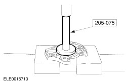
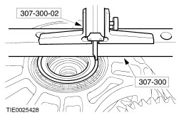
Using the special tool, set the depth gauge to zero. - Position the gauge on the measuring bar (or measuring plate) and slide down the depth gauge as far as possible.
- Zero the gauge.
| | | -
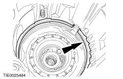
Using the special tool, measure the distance between the gauge bar and the reverse brake servo piston. - Push the reverse brake servo piston in the direction of the arrow as far as possible.
- Place the gauge bar onto outer race of the one-way clutch.
- Measure the distance between gauge bar and inner edge of piston.
- Measure the thickness of the gauge bar.
- The measured value is for example (X1): 51.80 mm - 48.2 mm = 3.60 mm.
| | | -
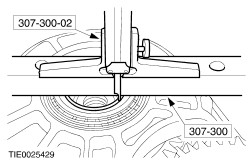
Using the special tool, measure the distance between the gauge bar and the reverse brake plates. - Press the clutches and pressure plate together.
- Measure the distance between gauge bar and pressure plates.
- Measure the thickness of the gauge bar.
- The measure value is for example (X2): 77.20 mm - 48.2 mm = 29.00 mm.
| | | -
Calculate the reverse brake assembly adjusting shim. - The constant value = 30.60 mm
- The calculated adjusting shim X = 30.6 + X1/2 - X2
- Example: 30.60 mm + 3.6/2 mm - 29.00 mm = 3.40 mm
- The adjusting shims are categorised in steps.
For additional information, refer to Specifications in this section.
| | | -
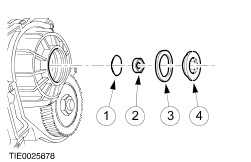
NOTE:The flat side on the thrust plate must be facing the clutch plates. NOTE:Install the Belleville washer with the domed side upwards. Install the reverse brake plate assembly. - Install the shim.
- Install the reverse clutch steel and friction plates.
- Install the thrust plate.
- Install the Belleville washer.
| | | -
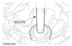
Using the special tool, install the one-way clutch. | | | -
NOTE:Install the circlip openings around the one-way clutch retaining wedge. Install the one-way clutch circlips. | | | -
NOTE:Install the circlip openings around the one-way clutch retaining wedge. Install the clutch plate cage intermediate and overdrive brake circlip. | | | -
NOTE:If the end-float is outside the tolerance, the clutch pack should be removed appropriate adjustment shim(s) installed. NOTE:If adjustment of over 2 mm is necessary, use two shims. Using a feeler gauge, measure the clearance between the reverse brake plates . | | | -
Install the large sun gear. | | | -
NOTE:The washer collar must be facing the large sun gear. Install the planetary gear input shafts. - Install the washer.
- Install the needle roller thrust bearing.
- Install the large drive shaft.
- Install the needle roller thrust bearing.
- Install the needle roller bearing.
- Install the planetary gear (small) input shaft.
| | | -
NOTE:Pass the special tool through the holes in the sun wheel to lock it, so that the planetary gear (small) input shaft bolt can be loosened or tightened. Using the special tool, lock the sun gear. | | | -
NOTE:Do not install the adjustment shim when making the setting. Install the planetary gear (small) input shaft retaining bolt and washer. | | | -
NOTE:Carry out the preparations and the measurement three times and calculate the average value of the measurements. Calculate the planetary gear set shim thickness. - Install the dial indicator gauge on the centre of the bolt head.
- Set the display to "zero".
- Hold the planetary gear (small) input shaft from inside the transaxle, push it upwards and measure the end float.
- Note the resulting measurement (e.g. 1.76 mm).
- Example: 1.76 mm + 1.78 mm + 1.77 mm divided by three = 1.77 mm.
- The adjusting shims are categorised in steps.
For additional information, refer to Specifications in this section.
| | | -
NOTE:Pass the special tool through the holes in the sun wheel to lock it, so that the planetary gear (small) input shaft bolt can be loosened or tightened. Using the special tool, lock the sun gear. | | | -
Remove planetary gear (small) input shaft retaining bolt. | | | -
Install the planetary gear adjusting shim. - Install the adjusting shim.
- Install the washer.
- Install the bolt.
| | | -
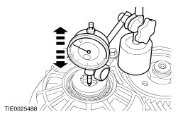
Measure the planetary gear set end float. - Install the dial indicator gauge on the centre of the bolt head.
- Set the display to "zero".
- Hold the planetary gear (small) input shaft from inside the transaxle, push it upwards and measure the end float.
| | | -
NOTE:The needle roller thrust bearing washer must be facing the planetary gear (small) input shaft. Using petroleum jelly, install the needle roller thrust bearing and washer. | | | -
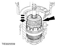
CAUTION:Press the low to direct clutch carefully on until the stop. Do not exert further pressure onto the clutches. NOTE:On some transaxles the low to direct clutch and the direct and overdrive clutch must be pressed together before installing. Using a suitable press and tube, assemble the low to direct clutch on the direct and overdrive clutch. - Install the low to direct clutch.
- Install the direct and overdrive clutch.
| | | -
NOTE:If the splines are not visible, the installation is correct. Check the low to direct clutch and the direct and overdrive clutch for correct installation. | | | -
Install the direct and overdrive clutch assembly. | | | -
Install the low to direct clutch assembly. | | | -
CAUTION:Do not install the adjustment shim. Install the reverse clutch assembly. | | | -
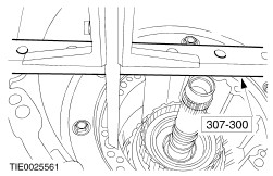
NOTE:The input gear should be facing downwards for the measuring procedure. Using the special tool, measure the distance between the transaxle case and the low to direct clutch. - Press the clutches together and hold them in position.
- Use a suitable depth gauge, measure the distance.
- Repeat the measurement on the opposite side, and calculate the average value.
- The measured value is for example (X1): = 193.70 mm.
| | | -
Using the special tool, measure the distance between the transaxle case and the transaxle oil pump flange. - Use a suitable depth gauge, measure the distance.
- Repeat the measurement on the opposite side, and calculate the average value.
- The measured value is for example (X2): = 140.00 mm.
| | | -
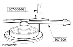
NOTE:Make sure that the oil pump gasket is installed. Using the special tools, measure the distance between the transaxle oil pump flange and the oil pump stator. - Place the gauge bar on top of the stator shaft (seat of the shims).
- Measure the distance from the gauge bar to the oil pump flange gasket.
- Repeat the measurement on the opposite side and take the average.
- Measure the thickness of the gauge bar.
- The measured value is for example (X3): 69.10 mm - 17.90 mm = 51.20 mm.
| | | -
Calculate the adjusting shim for the low to direct clutch and the reverse clutch. - The calculated adjusting shim (X) = X1 - X2 - X3.
- Example : 193.70 mm - 140.00 mm - 51.20 mm = 2.5 mm.
- The adjusting shims are categorised in steps.
For additional information, refer to Specifications in this section.
| | | -
Remove the reverse clutch. | | | -
NOTE:If the required shim thickness is 2 mm or greater, two or three shims can be fitted. Install the low to direct gear clutch shims. | | | -
Install the reverse clutch. | | | -
NOTE:These adjustment procedures for the intermediate and overdrive brake assembly are valid for transaxles lettered CYF and DAH only. NOTE:Do not install the last steel plate (3 mm) and the waved washer. Install the intermediate and overdrive brake assembly. - Install the clutch plate cage circlip.
- Install the clutch plate cage so, that notch locates on freewheel wedge.
- Install the 3 mm steel plate.
- Install the three spring retainers in the 3 mm steel plate.
- Install the three springs.
- Install the steel and friction plates.
| | | -
NOTE:These adjustment procedures for the intermediate and overdrive brake assembly are valid for transaxles lettered CYF and DAH only. Using the special tool, set the depth selection to zero. - Position the gauge on the measuring bar (or measuring plate) and slide down the depth gauge as far as possible.
- Zero the gauge.
| | | -
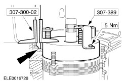
NOTE:These adjustment procedures for the intermediate and overdrive brake assembly are valid for transaxles lettered CYF and DAH only. Install the special tools and measure the distance between the special tool and transaxle oil pump flange. - Attach the measuring fixture with three bolts to the transaxle oil pump flange and tighten the bolts.
- Measure the distance between the transmission housing oil pump flange and the top edge of the measuring fixture.
- Record the measured value.
- Repeat the measurement on the opposite side and calculate the average value.
- Measure the height of the measuring fixture.
- The measured value is for example (X1): 60.00 mm - 29.80 mm = 30.20 mm.
- Detach the measuring fixture.
| | | -
NOTE:These adjustment procedures for the intermediate and overdrive brake assembly are valid for transaxles lettered CYF and DAH only. NOTE:Make sure that the oil pump gasket is installed. Using the special tool, measure the distance between the transaxle oil pump flange and the overdrive clutch piston. - Push the intermediate and overdrive clutch piston onto the stator shaft.
- Place the gauge bar on top of the intermediate and overdrive clutch piston.
- Measure the distance between the gauge bar and the oil pump flange gasket.
- Repeat the measurement on the opposite side and calculate the average value.
- Measure the thickness of the gauge bar.
- The measured value is for example (X2): 40.10 mm - 19.50 mm = 20.60 mm.
| | | -
NOTE:These adjustment procedures for the intermediate and overdrive brake assembly are valid for transaxles lettered CYF and DAH only. Calculate the intermediate and overdrive brake adjusting steel plate. - The setting caused by the force exerted with the measuring fixture = 3.60 mm
- The calculated steel plate thickness X = X1 - X2 - 3.60 mm
- Example: 30.20 mm - 20.60 mm - 3.60 mm = 6.00 mm
- The adjusting steel plates are categorised in steps.
For additional information, refer to Specifications in this section.
| | | -
NOTE:These adjustment procedures for the intermediate and overdrive brake assembly are valid for transaxles lettered CYF and DAH only. Install the upper spring cups. | | | -
NOTE:These adjustment procedures for the intermediate and overdrive brake assembly are valid for transaxles lettered CYF and DAH only. Install the appropriate adjusting steel plate. | | | -
NOTE:These adjustment procedures for the intermediate and overdrive brake assembly are valid for transaxles lettered CYF and DAH only. Install the waved washer. | | | -
NOTE:The adjustment procedures for the intermediate and overdrive brake assembly are valid only for transaxles with a shim and retaining ring installed. Install the intermediate and the overdrive brake assembly. - Install the clutch plate cage, so that notch locates on freewheel wedge.
- Install the 3 mm steel plate.
- Install the three spring retainers in the 3 mm steel plate.
- Install the three springs.
- Install the steel and friction plates.
| | | -
NOTE:The adjustment procedures for the intermediate and overdrive brake assembly are valid only for transaxles with a shim and retaining ring installed. Install the retaining ring with the smooth side facing the steel plate. | | | -
NOTE:The adjustment procedures for the intermediate and overdrive brake assembly are valid only for transaxles with a shim and retaining ring installed. Using the special tool, set the depth gauge to zero. - Position the gauge on the measuring bar (or measuring plate) and slide down the depth gauge.
- Zero the gauge.
| | | -
NOTE:The adjustment procedures for the intermediate and overdrive brake assembly are valid only for transaxles with a shim and retaining ring installed. Install the special tools and measure the distance between the special tool and transaxle oil pump flange. - Attach the measuring fixture with three bolts to the transaxle oil pump flange and tighten the bolts.
- Measure the distance between the transmission housing oil pump flange and the top edge of the measuring fixture.
- Repeat the measurement on the opposite side and calculate the average value.
- Record the measured value.
- Detach the measuring fixture.
- Measure the height of the measuring fixture.
- The measured value is for example (X1): 60.00 mm - 32.70 mm = 27.30 mm.
- Remove the retaining ring.
| | | -
NOTE:Make sure that the oil pump gasket is installed. NOTE:The adjustment procedures for the intermediate and overdrive brake assembly are valid only for transaxles with a shim and retaining ring installed. Using the special tools, measure the distance between the transaxle oil pump flange and the overdrive clutch piston. - Push the intermediate and overdrive clutch piston into the stator shaft.
- Place the gauge bar on top of the intermediate and overdrive clutch piston.
- Measure the distance between the gauge bar and the oil pump flange gasket.
- Repeat the measurement on the opposite side, and calculate the average value.
- Measure the thickness of the gauge bar.
- The measured value is for example (X2): 39.80 mm - 19.50 mm = 20.30 mm.
- Remove the measuring fixture.
| | | -
NOTE:The adjustment procedures for the intermediate and overdrive brake assembly are valid only for transaxles with a shim and retaining ring installed. Calculate the intermediate and overdrive brake adjusting shim. - The setting caused by the force exerted with the measuring fixture = 2.65 mm.
- The calculated shim = X1 - X2 - 2.65 mm
- Example: 27.30 mm - 20.30 mm - 2.65 mm = 4.35 mm
- The adjusting shims are categorised in steps.
For additional information, refer to Specifications in this section.
| | | -
NOTE:The adjustment procedures for the intermediate and overdrive brake assembly are valid only for transaxles with a shim and retaining ring installed. Install the upper spring cups. | | | -
NOTE:The adjustment procedures for the intermediate and overdrive brake assembly are valid only for transaxles with a shim and retaining ring installed. Install the steel plate (3 mm). | | | -
NOTE:The adjustment procedures for the intermediate and overdrive brake assembly are valid only for transaxles with a shim and retaining ring installed. Install the appropriate adjustment shim(s). | | | -
NOTE:The adjustment procedures for the intermediate and overdrive brake assembly are valid only for transaxles with a shim and retaining ring installed. Install the retaining ring with the smooth side facing the steel plate. | | | -
Install the strainer, if equipped. | | | -
CAUTION:Do not damage the oil pump flange gasket or the oil pump O-ring. Install the transaxle fluid pump. | | | -
NOTE:Install new transaxle fluid pump retaining bolts. Install the transaxle fluid pump retaining bolts. - Tighten the bolts in a diagonal sequence.
| | | -
NOTE:If the measured value is out of tolerance, correct the low to direct clutch shim (see previous steps). Using the special tool, measure the reverse gear clutch end float. - Install the dial indicator gauge.
- Set the dial indicator to "zero".
- Move the turbine shaft up and down.
- Repeat the measurement, calculate the average value.
- Note the values indicated.
| | | -
NOTE:Install a new torque converter impeller hub seal. Using the special tool, install the torque converter impeller hub seal. | | | -
Install the main control valve body sealing plug. | | | -
Install the manual valve link. - Set the main control valve body into installation position.
- Turn the manual valve so that the angled face points towards the manual valve link.
- Attach the manual valve link to the manual valve.
| | | -
Install the main control valve body. - Tighten the bolts in a diagonal sequence.
| | | -
NOTE:Install a new manual valve retaining clip and bolt. NOTE:When tightening the manual valve retaining bolt, hold the manual valve in the direction of the arrow. Adjust the manual valve link. - Set the manual control lever to "P" position.
- Install the manual valve link and manual valve as far as possible into the main control valve body (arrow direction) and tighten the bolt.
| | | -
NOTE:Insert transmission range (TR) sensor so that each pin rests on a slope of the detent segment. Install the TR sensor. | | | -
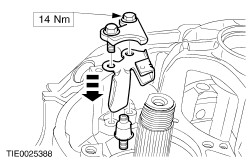
Install the conducting foil assembly. - Connect the electrical connectors.
- Install the retaining bolt.
| | | -
NOTE:Install a new oil filter seal. Install the oil filter seal. | | | -
NOTE:Install a new fluid pan drain plug seal. NOTE:Install a new fluid pan gasket. Install the fluid pan. - Install the spacer sleeves.
- Install the gasket.
- Install the permanent magnet.
- Install the fluid pan.
- Install the fluid pan retaining bolts.
- Install the overflow pipe.
- Install the oil drain plug.
| | | -
NOTE:Install new oil cooler retaining bolts and O-rings. Install the oil cooler. | | | -
Install the manual control lever. | | | -
NOTE:Install a new transaxle rear housing cover gasket. Install the transaxle rear housing cover. | | | -
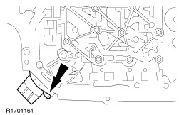
Install the turbine shaft speed (TSS) sensor. | | | -
Install the vehicle speed sensor (VSS). | | | -
Install the wiring loom. - Connect the TR sensor, the TSS sensor and the VS sensor electrical connectors.
| | | -
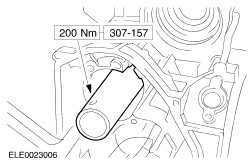
Install the torque converter. - Install the drive spigots in the recesses in the oil pump inner gear.
| | |