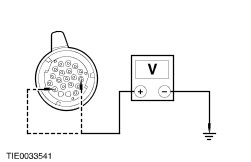
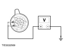
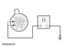
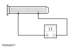
| Diagnosis and Testing Pinpoint Tests | PINPOINT TEST A : TRANSMISSION RANGE (TR) SENSOR – UNDEFINED SWITCH STATE | | TEST CONDITIONS | DETAILS/RESULTS/ACTIONS | | A1: CHECK FOR VOLTAGE TO THE TRANSMISSION RANGE (TR) SENSOR | | | 1 Disconnect TR Sensor electrical connector C156. | | | 2 Ignition switch in position II. | | | 3 Measure the voltage between the TR sensor electrical connector C156 pin 3, (BK), harness side and ground. | | | Is the voltage greater than 10 volts? Yes No REPAIR circuit (BK). TEST the system for normal operation. | | A2: CHECK THE TR SENSOR GROUND CIRCUIT FOR CONTINUITY | | | 1 Ignition switch in position 0. | | | 2 Measure the resistance between the TR sensor electrical connector C156 pin 6, (BN), harness side and ground. | | | Is the resistance less than 5 ohms? Yes No REPAIR circuit (BN). TEST the system for normal operation. | | A3: CHECK THE TR SENSOR CIRCUITS FOR CONTINUITY | | | 1 Disconnect Transmission Control Module (TCM) electrical connector C55. | | | 2 Measure the resistance between the: - TCM electrical connector C55 pin 18, (GN/BK), harness side and the TR sensor electrical connector C156 pin 5, (GN/BK), harness side; and
- TCM electrical connector C55 pin 19, (YE/BU), harness side and the TR sensor C156 pin 7, (YE/BU), harness side; and
- TCM electrical connector C55 pin 40, (RD/YE), harness side and the TR sensor electrical connector C156 pin 2, (RD/YE), harness side; and
- TCM electrical connector C55 pin 41, (VT/BK), harness side and the TR sensor electrical connector C156 pin 4, (VT/BK), harness side.
| | | Are the resistances less than 5 ohms? Yes No REPAIR circuit (GN/BK), or (YE/BU), or (RD/YE) or (VT/BK). TEST the system for normal operation. | | A4: CHECK THE TR SENSOR CIRCUIT FOR SHORT TO GROUND | | | 1 Measure the resistance between the: - TCM electrical connector C55 pin 18, (GN/BK), harness side and ground; and
- TCM electrical connector C55 pin 19, (YE/BU), harness side and ground; and
- TCM electrical connector C55 pin 40, (RD/YE), harness side and ground; and
- TCM electrical connector C55 pin 41, (VT/BK), harness side and ground.
| | | Are the resistances greater than 10,000 ohms? Yes No REPAIR circuit (GN/BK), (YE/BU), (RD/YE) or (VT/BK). TEST the system for normal operation. | | A5: CHECK FOR VOLTAGE TO THE TR SENSOR | | | 1 Ignition switch in position II. | | | 2 Measure the voltage between the: - TCM electrical connector C55 pin 18, (GN/BK), harness side and ground; and
- TCM electrical connector C55 pin 19, (YE/BU), harness side and ground; and
- TCM electrical connector C55 pin 40, (RD/YE), harness side and ground; and
- TCM electrical connector C55 pin 41, (VT/BK), harness side and ground
| | | Is any voltage present? Yes REPAIR circuit (GN/BK), or (YE/BU), or (RD/YE) or (VT/BK). TEST the system for normal operation. No | | A6: CHECK THE TR SENSOR CIRCUIT FOR SHORT TO GROUND | | | 1 Ignition switch in position 0. | | | 2 Measure the resistance between the: - TCM electrical connector C55 pin 18, (GN/BK), harness side and pin19, (YE/BU), harness side; and
- TCM electrical connector C55 pin 18, (GN/BK), harness side and pin 40, (RD/YE), harness side; and
- TCM electrical connector C55 pin 18, (GN/BK), harness side and pin 41, (VT/BK), harness side; and
- TCM electrical connector C55 pin 19, (YE/BU), harness side and pin 40, (RD/YE), harness side; and
- TCM electrical connector C55 pin 19, (YE/BU), harness side and pin 41, (VT/BK), harness side; and
- TCM electrical connector C55 pin 40, (RD/YE), harness side and pin 41, (VT/BK), harness side.
| | | Are the resistances greater than 10,000 ohms? Yes INSTALL a new TR sensor.
REFER to: Transmission Range (TR) Sensor (307-01B Automatic Transmission/Transaxle - Vehicles With: AG5, In-vehicle Repair).
No REPAIR circuit (GN/BK), or (YE/BU), or (RD/YE). TEST the system for normal operation. | | PINPOINT TEST B : TRANSMISSION FLUID TEMPERATURE (TFT) SENSOR | | TEST CONDITIONS | DETAILS/RESULTS/ACTIONS | | B1: CHECK FOR VOLTAGE TO THE TFT SENSOR | | | 1 Disconnect Transaxle electrical connector C108. | | | 2 Ignition switch in position II. | | | 3 Measure the voltage between the transaxle electrical connector C108 pin 7 (RD), harness side and ground. | | | Is any voltage present? Yes No | | B2: CHECK THE TRANSMISSION CONTROL MODULE (TCM) HARNESS FOR A SHORT TO POWER | | | 1 Ignition switch in position 0. | | | 2 Disconnect TCM electrical connector C55. | | | 3 Ignition switch in position II. | | | 4 Measure the voltage between the: - transaxle electrical connector C108 pin 7, (RD), harness side and ground; and
- transaxle electrical connector C108 pin 8, (RD/BN), harness side and ground.
| | | Is any voltage present? Yes REPAIR circuit (RD) or (RD/BN). TEST the system for normal operation. No | | B3: CHECK THE TRANSMISSION CONTROL MODULE (TCM) HARNESS FOR A SHORT TO GROUND | | | 1 Ignition switch in position 0. | | | 2 Disconnect TCM electrical connector C55. | | | 3 Measure the resistance between the: - transaxle electrical connector C108 pin 7, (RD), harness side and ground; and
- transaxle electrical connector C108 pin 8, (RD/BN), harness side and ground.
| | | Are the resistances less than 5 ohms? Yes REPAIR circuit (RD) or (RD/BN). TEST the system for normal operation. No | | B4: CHECK THE CONTINUITY OF THE TCM HARNESS | | | 1 Ignition switch in position 0. | | | 2 Measure the resistance between the TCM electrical connector C55 pin 34, (RD/BN), harness side and the transaxle electrical connector C108 pin 8, (RD/BN), harness side. | | | Is the resistance less than 5 ohms? Yes INSTALL a new transaxle. TEST the system for normal operation. No REPAIR circuit (RD/BN). TEST the system for normal operation. | | B5: CHECK THE CONTINUITY OF THE TCM HARNESS | | | 1 Ignition switch in position 0. | | | 2 Measure the resistance between the TCM electrical connector C55 pin 33, (RD), harness side and the transaxle electrical connector C108 pin 7, (RD), harness side. | | | Is the resistance less than 5 ohms? Yes INSTALL a new TCM. No REPAIR circuit (RD). TEST the system for normal operation. | | PINPOINT TEST C : TURBINE SHAFT SPEED (TSS) SENSOR | | TEST CONDITIONS | DETAILS/RESULTS/ACTIONS | | C1: CHECK THE RESISTANCE OF THE TSS SENSOR | | | 1 Disconnect Transmission Control Module (TCM) electrical connector C55. | | | 2 Measure the resistance between transmission control module (TCM) electrical connector C55 pin 9, (GY/WH), harness side and the TCM electrical connector C55 pin 10, (GY/RD), harness side. | | | Is the resistance approximately 550 ohms? Yes INSTALL a new TCM. TEST the system for normal operation. No | | C2: CHECK THE TRANSMISSION CONTROL MODULE (TCM) HARNESS FOR A SHORT TO GROUND | | | 1 Disconnect Transaxle electrical connector C108. | | | 2 Measure the resistance between the: - transaxle electrical connector C108 pin 1, (GY/RD), harness side and ground; and
- transaxle electrical connector C108 pin 2, (GY/WH), harness side and ground.
| | | Are the resistances greater than 10,000 ohms? Yes No REPAIR circuit (GY/RD) or (GY/WH). TEST the system for normal operation. | | C3: CHECK THE CONTINUITY OF THE TCM HARNESS | | | 1 Measure the resistance between the: - TCM electrical connector C55 pin 9, (GY/WH), harness side and the transaxle electrical connector C108 pin 2, (GY/WH), harness side; and
- TCM electrical connector C55 pin 10, (GY/WH), harness side and the transaxle electrical connector C108 pin 1, (GY/RD), harness side.
| | | Are the resistance less than 5 ohms? Yes INSTALL a new transaxle. Test the system for normal operation. No REPAIR circuit (GY/WH) or (GY/RD/). TEST the system for normal operation. | | PINPOINT TEST D : VEHICLE SPEED SENSOR (VSS) | | TEST CONDITIONS | DETAILS/RESULTS/ACTIONS | | D1: CHECK THE RESISTANCE OF THE VSS SENSOR | | | 1 Disconnect Transmission Control Module (TCM) electrical connector C55. | | | 2 Measure the resistance between the transmission control module (TCM) electrical connector C55 pin 35, (OG/VT), harness side and the TCM electrical connector C55 pin 36, (OG/BN), harness side. | | | Is the resistance approximately 550 ohms? Yes INSTALL a new TCM. TEST the system for normal operation. No | | D2: CHECK THE TRANSMISSION CONTROL MODULE (TCM) HARNESS FOR A SHORT TO GROUND | | | 1 Disconnect Transaxle electrical connector C108. | | | 2 Measure the resistance between the: - transaxle electrical connector C108 pin 5, (OG/BN), harness side and ground; and
- transaxle electrical connector C108 pin 6, (OG/VT), harness side and ground.
| | | Are the resistances greater than 10,000 ohms? Yes No REPAIR circuit (OG/BN) or (OG/VT). TEST the system for normal operation. | | D3: CHECK THE CONTINUITY OF THE TCM HARNESS | | | 1 Measure the resistance between the: - transmission control module (TCM) electrical connector C55, pin 35 (OG/VT), harness side and the transaxle electrical connector C108 pin 6, (OG/VT), harness side; and
- TCM electrical connector C55 pin 36, (OG/BN), harness side and the transaxle electrical connector C108 pin 5, (OG/BN), harness side.
| | | Are the resistances less than 5 ohms? Yes INSTALL a new transaxle. TEST the system for normal operation. No REPAIR circuit (OG/VT) or (OG/BN). TEST the system for normal operation. | | PINPOINT TEST E : LOCK UP SOLENOID | | TEST CONDITIONS | DETAILS/RESULTS/ACTIONS | | E1: CHECK THE RESISTANCE OF THE LOCK UP SOLENOID | | | 1 Disconnect Transmission Control Module (TCM) electrical connector C55. | | | 2 Measure the resistance between the transmission control module (TCM) electrical connector C55 pin 25, (GY/WH), harness side and the TCM electrical connector C55 pin 64, (BK), harness side. | | | Is the resistance approximately 12 ohms? Yes INSTALL a new TCM. TEST the system for normal operation. No | | E2: CHECK THE TRANSMISSION CONTROL MODULE (TCM) HARNESS FOR SHORT TO POWER | | | 1 Disconnect Transaxle electrical connector C108. | | | 2 Ignition switch in position II. | | | 3 Measure the voltage between the - transaxle electrical connector C108 pin 17, (GY/WH), harness side and ground; and
- transaxle electrical connector C108 pin 18, (BK), harness side and ground.
| | | Is any voltage present? Yes REPAIR circuit (GY/WH) or (BK). TEST the system for normal operation. No | | E3: CHECK THE TRANSMISSION CONTROL MODULE (TCM) HARNESS FOR A SHORT TO GROUND | | | 1 Ignition switch in position 0. | | | 2 Measure the resistance between the: - transaxle electrical connector C108 pin 17, (GY/WH), harness side and ground; and
- transaxle electrical connector C108 pin 18, (BK), harness side and ground.
| | | Are the resistances less than 5 ohms? Yes REPAIR circuit (GY/WH) or (BK). TEST the system for normal operation. No | | E4: CHECK THE CONTINUITY OF THE TRANSMISSION CONTROL MODULE (TCM) HARNESS | | | 1 Measure the resistance between the: - TCM electrical connector C55 pin 25, (GY/WH), harness side and the transaxle electrical connector C108 pin 17, (GY/WH), harness side; and
- TCM electrical connector C55 pin 64, (BK), harness side and the transaxle electrical connector C108 pin 18, (BK), harness side.
| | | Are the resistances less than 5 ohms? Yes INSTALL a new lock up solenoid. TEST the system for normal operation. No REPAIR circuit (GY/WH) or (BK). TEST the system for normal operation. | | PINPOINT TEST F : LINE PRESSURE SOLENOID | | TEST CONDITIONS | DETAILS/RESULTS/ACTIONS | | F1: CHECK THE RESISTANCE OF THE LINE PRESSURE SOLENOID | | | 1 Disconnect Transmission Control Module (TCM) electrical connector C55. | | | 2 Measure the resistance between the transmission control module (TCM) electrical connector C55 pin 64, (YE), harness side and the TCM electrical connector C55 pin 66, (BK), harness side. | | | Is the resistance approximately 3 ohms? Yes INSTALL a new TCM. TEST the system for normal operation. No | | F2: CHECK THE TRNSMISSION CONTROL MODULE (TCM) HARNESS FOR SHORT TO POWER | | | 1 Disconnect Transaxle electrical connector C108. | | | 2 Ignition switch in position II. | | | 3 Measure the voltage between the: - transaxle electrical connector C108 pin 15, (YE), harness side and ground; and
- transaxle electrical connector C108 pin 18, (BK), harness side and ground.
| | | Is any voltage present? Yes REPAIR circuit (YE) or (BK). TEST the system for normal operation. No | | F3: CHECK THE TCM HARNESS FOR A SHORT TO GROUND | | | 1 Ignition switch in position 0. | | | 2 Measure the resistance between the: - transaxle electrical connector C108 pin 15, (YE), harness side and ground; and
- transaxle electrical connector C108 pin 18, (BK), harness side and ground.
| | | Are the resistances greater than 10,000 ohms? Yes No REPAIR circuit (YE) or (BK). TEST the system for normal operation. | | F4: CHECK THE CONTINUITY OF THE TCM HARNESS | | | 1 Measure the resistance between the: - TCM electrical connector C55 pin 66, (YE), harness side and the transaxle electrical connector C108 pin 15, (YE), harness side; and
- TCM electrical connector C55 pin 64, (BK), harness side and the transaxle electrical connector C108 pin 18, (BK), harness side.
| | | Are the resistances less than 5 ohms? Yes INSTALL a new line pressure solenoid. TEST the system for normal operation. No REPAIR circuit (YE) or (BK). TEST the system for normal operation. | | PINPOINT TEST G : SHIFT SOLENOID A | | TEST CONDITIONS | DETAILS/RESULTS/ACTIONS | | G1: CHECK THE RESISTANCE OF THE SHIFT SOLENOID EV6 | | | 1 Disconnect Transmission Control Module (TCM) electrical connector C55. | | | 2 Measure the resistance between the transmission control module (TCM) electrical connector C55 pin 48, (GY), harness side and the TCM electrical connector C55 pin 64, (BK), harness side. | | | Is the resistance approximately 16 ohms? Yes INSTALL a new TCM. TEST the system for normal operation. No | | G2: CHECK THE TCM HARNESS FOR SHORT TO POWER | | | 1 Disconnect Transaxle electrical connector C108. | | | 2 Ignition switch in position II. | | | 3 Measure the voltage between the: - transaxle electrical connector C108 pin 9, (GY), harness side and ground; and
- transaxle electrical connector C108 pin 18, (BK), harness side and ground.
| | | Is any voltage present? Yes REPAIR circuit (GY) or (BK). TEST the system for normal operation. No | | G3: CHECK THE TCM HARNESS FOR A SHORT TO GROUND | | | 1 Ignition switch in position 0. | | | 2 Measure the resistance between the: - transaxle electrical connector C108 pin 9, (GY), harness side and ground; and
- transaxle electrical connector C108 pin 18, (BK), harness side and ground.
| | | Is the resistance greater than 10,000 ohms? Yes No REPAIR circuit (GY) or (BK). TEST the system for normal operation. | | G4: CHECK THE CONTINUITY OF THE TCM HARNESS | | | 1 Measure the resistance between the: - TCM electrical connector C55 pin 48, (GY), harness side and the transaxle electrical connector C108 pin 9, (GY), harness side; and
- TCM electrical connector C55 pin 64, (BK), harness side and the transaxle electrical connector C108 pin 18, (BK), harness side.
| | | Are the resistances less than 5 ohms? Yes INSTALL a new shift solenoid EV6. TEST the system for normal operation. No REPAIR circuit (GY) or (BK). TEST the system for normal operation. | | PINPOINT TEST H : SHIFT SOLENOID B | | TEST CONDITIONS | DETAILS/RESULTS/ACTIONS | | H1: CHECK THE RESISTANCE OF THE SHIFT SOLENOID EV5 | | | 1 Disconnect Transmission Control Module (TCM) electrical connector C55. | | | 2 Measure the resistance between the TCM electrical connector C55 pin 49, (GN/WH), harness side and the TCM electrical connector C55 pin 64, (BK), harness side. | | | Is the resistance approximately 16 ohms? Yes INSTALL a new TCM. TEST the system for normal operation. No | | H2: CHECK THE TCM HARNESS FOR SHORT TO POWER | | | 1 Disconnect Transaxle electrical connector C108. | | | 2 Ignition switch in position II. | | | 3 Measure the voltage between the: - transaxle electrical connector C108 pin 10, (GN/WH), harness side and ground; and
- transaxle electrical connector C108 pin 18, (BK), harness side and ground.
| | | Is any voltage present? Yes REPAIR circuit (GN/WH) or (BK). TEST the system for normal operation. No | | H3: CHECK THE TCM HARNESS FOR A SHORT TO GROUND | | | 1 Ignition switch in position 0. | | | 2 Measure the resistance between the: - transaxle electrical connector C108 pin 10, (GN/WH), harness side and ground; and
- transaxle electrical connector C108 pin 18, (BK), harness side and ground.
| | | Are the resistances greater than 10,000 ohms? Yes No REPAIR circuit (GN/WH) or (BK). TEST the system for normal operation. | | H4: CHECK THE CONTINUITY OF THE TCM HARNESS | | | 1 Measure the resistance between the: - TCM electrical connector C55 pin 49, (GN/WH), harness side and the transaxle electrical connector C108 pin 10, (GN/WH), harness side; and
- TCM electrical connector C55 pin 64, (BK), harness side and transaxle electrical connector C108 pin 18, (BK), harness side.
| | | Are the resistances less than 5 ohms? Yes INSTALL a new shift solenoid EV5. TEST the system for normal operation. No REPAIR circuit (GN/WH) or (BK). TEST the system for normal operation. | | PINPOINT TEST I : SHIFT SOLENOID C | | TEST CONDITIONS | DETAILS/RESULTS/ACTIONS | | I1: CHECK THE RESISTANCE OF THE SHIFT SOLENOID EV8 | | | 1 Disconnect Disconnect Transmission Control Module (TCM) electrical connector C55. | | | 2 Measure the resistance between the TCM electrical connector C55 pin 50, (BU/WH), harness side and the TCM electrical connector C55 pin 64, (BK), harness side. | | | Is the resistance approximately 16 ohms? Yes INSTALL a new TCM. TEST the system for normal operation. No | | I2: CHECK THE TCM HARNESS FOR SHORT TO POWER | | | 1 Disconnect Transaxle electrical connector C108. | | | 2 Ignition switch in position II. | | | 3 Measure the voltage between the: - transaxle electrical connector C108 pin 11, (BU/WH), harness side and ground; and
- transaxle electrical connector C108 pin 18, (BK), harness side and ground.
| | | Is any voltage present? Yes REPAIR circuit (BU/WH) or (BK). TEST the system for normal operation. No | | I3: CHECK THE TCM HARNESS FOR A SHORT TO GROUND | | | 1 Ignition switch in position 0. | | | 2 Measure the resistance between the: - transaxle electrical connector C108 pin 11, (BU/WH), harness side and ground; and
- transaxle electrical connector C108 pin 18, (BK), harness side and ground.
| | | Are the resistances greater than 10,000 ohms? Yes No REPAIR circuit (BU/WH) or (BK). TEST the system for normal operation. | | I4: CHECK THE CONTINUITY OF THE TCM HARNESS | | | 1 Measure the resistance between the: - TCM electrical connector C55 pin 50, (BU/WH), harness side and the transaxle electrical connector C108 pin 11, (BU/WH), harness side; and
- TCM electrical connector C55 pin 64, (BK), harness side and the transaxle electrical connector C108 pin 18, (BK), harness side.
| | | Are the resistances less than 5 ohms? Yes INSTALL a new shift solenoid EV8. TEST the system for normal operation. No REPAIR circuit (BU/WH) or (BK). TEST the system for normal operation. | | PINPOINT TEST J : 2-4 BRAKE TIMING SOLENOID | | TEST CONDITIONS | DETAILS/RESULTS/ACTIONS | | J1: CHECK THE RESISTANCE OF THE 2-4 BRAKE TIMING SOLENOID | | | 1 Disconnect Transmission Control Module (TCM) electrical connector C55. | | | 2 Measure the resistance between the TCM electrical connector C55 pin 51, (RD), harness side and the TCM electrical connector C55 pin 64, (BK), harness side. | | | Is the resistance approximately 16 ohms? Yes INSTALL a new TCM. TEST the system for normal operation. No | | J2: CHECK THE TCM HARNESS FOR SHORT TO POWER | | | 1 Disconnect Transaxle electrical connector C108. | | | 2 Ignition switch in position II. | | | 3 Measure the voltage between the: - transaxle electrical connector C108 pin 13, (RD), harness side and ground; and
- transaxle electrical connector C108 pin 18, (BK), harness side and ground.
| | | Is any voltage present? Yes REPAIR circuit (RD) or (BK). TEST the system for normal operation. No | | J3: CHECK THE TCM HARNESS FOR A SHORT TO GROUND | | | 1 Ignition switch in position 0. | | | 2 Measure the resistance between the: - transaxle electrical connector C108 pin 13, (RD), harness side and ground; and
- transaxle electrical connector C108 pin 18, (BK), harness side and ground.
| | | Are the resistances greater than 10,000 ohms? Yes No REPAIR circuit (RD) or (BK). TEST the system for normal operation. | | J4: CHECK THE CONTINUITY OF THE TCM HARNESS | | | 1 Measure the resistance between the: - TCM electrical connector C55 pin 51, (RD), harness side and the transaxle electrical connector C108 pin 13, (RD), harness side; and
- TCM electrical connector C55 pin 64, (BK), harness side and the transaxle electrical connector C108 pin 18, (BK), harness side.
| | | Are the resistances less than 5 ohms? Yes INSTALL a new 2-4 brake timing solenoid. TEST the system for normal operation. No REPAIR circuit (RD) or (BK). TEST the system for normal operation. | | PINPOINT TEST K : REDUCTION TIMING SOLENOID | | TEST CONDITIONS | DETAILS/RESULTS/ACTIONS | | K1: CHECK THE RESISTANCE OF THE REDUCTION TIMING SOLENOID | | | 1 Disconnect Transmission Control Module (TCM) electrical connector C55. | | | 2 Measure the resistance between the TCM electrical connector C55 pin 46, (BU), harness side and the TCM electrical connector C55 pin 64, (BK), harness side. | | | Is the resistance approximately 16 ohms? Yes INSTALL a new TCM. TEST the system for normal operation. No | | K2: CHECK THE TCM HARNESS FOR SHORT TO POWER | | | 1 Disconnect Transaxle electrical connector C108. | | | 2 Ignition switch in position II. | | | 3 Measure the voltage between the: - transaxle electrical connector pin C108 14 (BU), harness side and ground; and
- transaxle electrical connector C108 pin 18 (BK), harness side and ground.
| | | Is any voltage present? Yes REPAIR circuit (BU) or (BK). TEST the system for normal operation. No | | K3: CHECK THE TCM HARNESS FOR A SHORT TO GROUND | | | 1 Ignition switch in position 0. | | | 2 Measure the resistance between the: - transaxle electrical connector pin C108 14, (BU), harness side and ground; and
- transaxle electrical connector C108 pin 18, (BK), harness side and ground.
| | | Are the resistances greater than 10,000 ohms? Yes No REPAIR circuit (BU) or (BK). TEST the system for normal operation. | | K4: CHECK THE CONTINUITY OF THE TCM HARNESS | | | 1 Measure the resistance between the: - TCM electrical connector C55 pin 46, (BU), harness side and the transaxle electrical connector C108 pin 14, (BU), harness side; and
- TCM electrical connector C55 pin 64, (BK), harness side and the transaxle electrical connector C108 pin 18, (BK), harness side.
| | | Are the resistances greater than 10,000 ohms? Yes INSTALL a new reduction timing solenoid. TEST the system for normal operation. No REPAIR circuit (BU) or (BK). TEST the system for normal operation. | | PINPOINT TEST L : 2-4 BRAKE DUTY SOLENOID | | TEST CONDITIONS | DETAILS/RESULTS/ACTIONS | | L1: CHECK THE RESISTANCE OF THE 2-4 BRAKE DUTY SOLENOID | | | 1 Disconnect Transmission Control Module (TCM) electrical connector C55. | | | 2 Measure the resistance between the TCM electrical connector C55 pin 64, (BK), harness side and the TCM electrical connector C55 pin 65, (GN), harness side. | | | Is the resistance approximately 3 ohms? Yes INSTALL a new TCM. TEST the system for normal operation. No | | L2: CHECK THE TCM HARNESS FOR SHORT TO POWER | | | 1 Disconnect Transaxle electrical connector C108. | | | 2 Ignition switch in position II. | | | 3 Measure the voltage between the: - transaxle electrical connector C108 pin 16, (GN), harness side and ground; and
- transaxle electrical connector C108 pin 18, (BK), harness side and ground.
| | | Is any voltage present? Yes REPAIR circuit (GN) or (BK). TEST the system for normal operation. No | | L3: CHECK THE TCM HARNESS FOR A SHORT TO GROUND | | | 1 Ignition switch in position 0. | | | 2 Measure the resistance between the: - transaxle electrical connector C108 pin 16, (GN), harness side and ground; and
- transaxle electrical connector C108 pin 18, (BK), harness side and ground.
| | | Is the resistance greater than 10,000 ohms? Yes No REPAIR circuit (GN) or (BK). TEST the system for normal operation. | | L4: CHECK THE CONTINUITY OF THE TCM HARNESS | | | 1 Measure the resistance between the: - TCM electrical connector C55 pin 65, (GN), harness side and the transaxle electrical connector C108 pin 16, (GN), harness side; and
- TCM electrical connector C55 pin 64, (BK), harness side and the transaxle connector C108 pin 18, (BK), harness side.
| | | Are the resistances less than 5 ohms? Yes INSTALL a new 2-4 brake duty solenoid. TEST the system for normal operation. No REPAIR circuit (GN) or (BK). TEST the system for normal operation. | | PINPOINT TEST M : LOW CLUTCH TIMING SOLENOID | | TEST CONDITIONS | DETAILS/RESULTS/ACTIONS | | M1: CHECK THE RESISTANCE OF THE LOW CLUTCH TIMING SOLENOID | | | 1 Disconnect Transmission Control Module (TCM) electrical connector C55. | | | 2 Measure the resistance between the TCM electrical connector C55 pin 26, (BK/WH), harness side and the TCM electrical connector C55 pin 64, (BK), harness side. | | | Is the resistance approximately 16 ohms? Yes INSTALL a new TCM. TEST the system for normal operation. No | | M2: CHECK THE TCM HARNESS FOR SHORT TO POWER | | | 1 Disconnect Transaxle electrical connector C108. | | | 2 Ignition switch in position II. | | | 3 Measure the voltage between the: - transaxle electrical connector C108 pin 12, (BK/WH), harness side and ground; and
- transaxle electrical connector C108 pin 18, (BK), harness side and ground.
| | | Is any voltage present? Yes REPAIR circuit (BK/WH) or (BK). TEST the system for normal operation. No | | M3: CHECK THE TCM HARNESS FOR A SHORT TO GROUND | | | 1 Ignition switch in position 0. | | | 2 Measure the resistance between the: - transaxle electrical connector C108 pin 12, (BK/WH), harness side and ground; and
- transaxle electrical connector C108 pin 18, (BK), harness side and ground.
| | | Are the resistances greater than 10,000 ohms? Yes No REPAIR circuit (BK/WH) or (BK). TEST the system for normal operation. | | M4: CHECK THE CONTINUITY OF THE TCM HARNESS | | | 1 Measure the resistance between the: - TCM electrical connector C55 pin 26, (BK/WH), harness side and the transaxle electrical connector C108 pin 12, (BK/WH), harness side; and
- TCM electrical connector C55 pin 64, (BK), harness side and the transaxle electrical connector C108 pin 18, (BK), harness side.
| | | Are the resistances less than 5 ohms? Yes INSTALL a new low clutch timing solenoid. TEST the system for normal operation. No REPAIR circuit (BK/WH) or (BK). TEST the system for normal operation. | | PINPOINT TEST N : INTERMEDIATE SHAFT SPEED SENSOR | | TEST CONDITIONS | DETAILS/RESULTS/ACTIONS | | N1: CHECK THE RESISTANCE OF THE INTERMEDIATE SHAFT SPEED SENSOR | | | 1 Disconnect Transmission Control Module (TCM) electrical connector C55. | | | 2 Measure the resistance between the TCM electrical connector C55 pin 28, (OG/GN), harness side, and the TCM electrical connector C55 pin 29, (OG/BN), harness side. | | | Is the resistance approximately 550 ohms? Yes INSTALL a new TCM. TEST the system for normal operation. No | | N2: CHECK THE TCM HARNESS FOR A SHORT TO GROUND | | | 1 Disconnect Transaxle electrical C108. | | | 2 Measure the resistance between the: - transaxle electrical connector C108 pin 3, (OG/GN), harness side and ground; and
- transaxle electrical connector C108 pin 4, (OG/BN), harness side and ground.
| | | Are the resistances greater than 10,000 ohms? Yes No REPAIR circuit (OG/GN) or (OG/BN). TEST the system for normal operation. | | N3: CHECK THE CONTINUITY OF THE TCM HARNESS | | | 1 Measure the resistance between the: - TCM electrical connector C55 pin 28, (OG/GN), harness side and the transaxle electrical connector C108 pin 3, (OG/GN), harness side.
- TCM electrical connector C55 pin 29, (OG/BN), harness side and the transaxle electrical connector C108 pin 4, (OG/BN), harness side.
| | | Are the resistances less than 5 ohms? Yes INSTALL a new intermediate shaft speed sensor. TEST the system for normal operation. No REPAIR circuit (OG/GN) or (OG/BN). TEST the system for normal operation. | | PINPOINT TEST O : COMMON GROUND LEAD OF MODULATED SOLENOIDS | | TEST CONDITIONS | DETAILS/RESULTS/ACTIONS | | O1: CHECK THE CONTINUITY OF THE TRANSMISSION CONTROL MODULE (TCM) HARNESS | | | 1 Disconnect TCM electrical C55. | | | 2 Disconnect Transaxle electrical connector C108. | | | 3 Measure the resistance between the TCM electrical connector C55 pin 64, (BK), harness side and the transaxle electrical connector C108 pin 18, (BK), harness side. | | | Is the resistance less than 5 ohms? Yes INSTALL a new TCM. TEST the system for normal operation. No REPAIR circuit (BK). TEST the system for normal operation. | | PINPOINT TEST P : TIPTRONIC ERROR-UP SHIFT | | TEST CONDITIONS | DETAILS/RESULTS/ACTIONS | | P1: CHECK FOR CONTINUITY BETWEEN THE TRANSMISSION CONTROL MODULE (TCM) AND THE TRANSMISSION SHIFT SELECTOR | | | 1 Disconnect Transmission Shift Selector electrical connector C160. | | | 2 Disconnect TCM electrical connector C55. | | | 3 Measure the resistance between the TCM electrical connector C55 pin 61, (WH/RD), harness side and the transmission shift selector electrical connector C160 pin 2, (WH/RD), harness side. | | | Is the resistance less than 5 ohms? Yes No REPAIR circuit (WH/RD). TEST the system for normal operation. | | P2: CHECK THE TRANSMISSION SHIFT SELECTOR HARNESS GROUND CIRCUIT | | | 1 Measure the resistance between the transmission shift selector electrical connector C160 pin 4, (BN), harness side and ground. | | | Is the resistance less than 5 ohms? Yes No REPAIR circuit (BN). TEST the system for normal operation. | | P3: CHECK THE TRANSMISSION SHIFT SELECTOR SWITCH | | | 1 With the aid of another technician, select and hold the gearshift selector in the positive position. | | | 2 Measure the resistance between the transmission shift selector electrical connector C160 pin 2, component side and the transmission shift selector electrical connector C160 pin 4, component side. | | | Is the resistance less than 5 ohms? Yes INSTALL a new TCM. TEST the system for normal operation. No INSTALL a new transmission shift selector switch. TEST the system for normal operation. | | PINPOINT TEST Q : TIPTRONIC ERROR-DOWN SHFT | | TEST CONDITIONS | DETAILS/RESULTS/ACTIONS | | Q1: CHECK FOR CONTINUITY BETWEEN THE TCM AND THE TRANSMISSION SHIFT SELECTOR | | | 1 Disconnect Transmission Shift Selector electrical connector C160. | | | 2 Disconnect Transmission Control Module (TCM) electrical connector C55. | | | 3 Measure the resistance between the TCM electrical connector C55 pin 62, (WH/BN), harness side and the transmission shift selector electrical connector C160 pin 3, (up to 05/2001 BN/RD or RD/BN from 05/2001), harness side. | | | Is the resistance less than 5 ohms? Yes No REPAIR circuit (WH/BN) or (BN/RD) or (RD/BN). TEST the system for normal operation. | | Q2: CHECK THE TRANSMISSION SHIFT SELECTOR HARNESS GROUND CIRCUIT | | | 1 Measure the resistance between the transmission shift selector electrical connector C160 pin 4, (BN), harness side and ground. | | | Is the resistance less than 5 ohms? Yes No REPAIR circuit (BN). TEST the system for normal operation. | | Q3: CHECK THE TRANSMISSION SHIFT SELECTOR SWITCH | | | 1 With the aid of another technician, select and hold the gearshift selector in the negative position. | | | 2 Measure the resistance between the transmission shift selector electrical connector C160 pin 3, component side and the transmission shift selector electrical connector C160 pin 4, component side. | | | Is the resistance less than 5 ohms? Yes INSTALL a new TCM. TEST the system for normal operation. No INSTALL a new transmission shift selector switch. TEST the system for normal operation. | | PINPOINT TEST R : TIPTRONIC ERROR SEQUENTIAL SHIFT SELECTED | | TEST CONDITIONS | DETAILS/RESULTS/ACTIONS | | R1: CHECK FOR CONTINUITY BETWEEN THE TRANSMISSION CONTROL MODULE (TCM) AND THE TRANSMISSION SHIFT SELECTOR | | | 1 Ignition switch in position 0. | | | 2 Disconnect Transmission Shift Selector electrical connector C160. | | | 3 Disconnect Transmission Control Module (TCM) electrical connector C55. | | | 4 Measure the resistance between the TCM electrical connector C55 pin 60, (WH/BN), harness side and the transmission shift selector electrical connector C160 pin 1, (WH/BN), harness side. | | | Is the resistance less than 5 ohms? Yes No REPAIR circuit (WH/BN). TEST the system for normal operation. | | R2: CHECK THE TRANSMISSION SHIFT SELECTOR HARNESS GROUND CIRCUIT | | | 1 Measure the resistance between the transmission shift selector electrical connector C160 pin 4, (BN), harness side and ground. | | | Is the resistance less than 5 ohms? Yes No REPAIR circuit (BN). TEST the system for normal operation. | | R3: CHECK THE TRANSMISSION SHIFT SELECTOR SWITCH | | | 1 Measure the resistance between the transmission shift selector electrical connector C160 pin 1, component side and the transmission shift selector electrical connector C160 pin 4, component side. | | | Is the resistance less than 5 ohms? Yes INSTALL a new TCM. TEST the system for normal operation. No INSTALL a new transmission shift selector switch. TEST the system for normal operation. | | |