| PINPOINT TEST A : THE SPEED CONTROL IS INOPERATIVE |
| TEST CONDITIONS | DETAILS/RESULTS/ACTIONS |
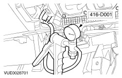
| A1: CHECK THE SPEED CONTROL VACUUM COMPONENTS FOR CORRECT OPERATION |
| | 1 Disconnect vacuum line from the vacuum pump. |
| | 2 Using the special tool, apply a vacuum on the speed control system until the throttle plate opens. |
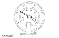
| | 3 Observe the vacuum gauge reading for a period of 1 minute. |
| | Does the vacuum reading remain constant for the required period? Yes No |
| A2: CHECK THE SPEED CONTROL VACUUM PUMP FOR CORRECT OPERATION |
| | 1 Check the speed control vacuum pump for correct operation, refer to the speed control vacuum pump component test in this section. |
| | Is the speed control vacuum pump operation OK? Yes No INSTALL a new speed control vacuum pump. TEST the system for normal operation. |
| A3: CHECK THE SPEED CONTROL VACUUM LINES, DEACTIVATOR SWITCHES AND ACTUATOR FOR CORRECT OPERATION |
| | 1 Disconnect the vacuum pump to brake pedal deactivator switch 'T' piece vacuum line. |
| | 2 Using the special tool, apply a vacuum on the speed control system until the accelerator pedal moves. |
| | 3 Observe the vacuum gauge reading for a period of 1 minute. |
| | Does the vacuum reading remain constant for the required period? Yes INSTALL a new vacuum line between the speed control vacuum pump and the first 'T' piece. TEST the system for normal operation. No |
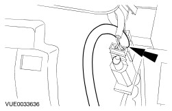
| A4: CHECK THE SPEED CONTROL BRAKE PEDAL DEACTIVATOR SWITCH FOR CORRECT OPERATION |
| | 1 Disconnect the brake pedal deactivator switch vacuum line. |
| | 2 Using the special tool, apply a vacuum to the brake pedal deactivator switch. |
| | 3 Observe the vacuum gauge reading for a period of 1 minute. |
| | Does the vacuum reading remain constant for the required period? Yes Vehicles with manual transaxle, GO to A5. Vehicles with automatic transaxle, GO to A6. . No INSTALL a new speed control brake pedal deactivator switch. TEST the system for normal operation. |
| A5: CHECK THE SPEED CONTROL CLUTCH PEDAL DEACTIVATOR SWITCH FOR CORRECT OPERATION |
| | 1 Disconnect the clutch pedal deactivator switch vacuum line. |
| | 2 Using the special tool, apply a vacuum to the clutch pedal deactivator switch. |
| | 3 Observe the vacuum gauge reading for a period of 1 minute. |
| | Does the vacuum reading remain constant for the required period? Yes No INSTALL a new speed control clutch pedal deactivator switch. TEST the system for normal operation. |
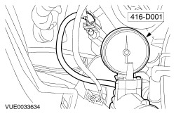
| A6: CHECK THE SPEED CONTROL ACTUATOR FOR CORRECT OPERATION |
| | 1 Disconnect vacuum line from the speed control actuator. |
| | 2 Using the special tool, apply a vacuum on the speed control actuator until the accelerator pedal moves. |
| | 3 Observe the vacuum gauge reading for a period of 1 minute. |
| | Does the vacuum reading remain constant for the required period? Yes INSTALL new vacuum lines between the deactivator switches and actuator. TEST the system for normal operation. No INSTALL a new speed control actuator. TEST the system for normal operation. |
| A7: CHECK FOR POWER AND GROUND TO THE STEERING WHEEL SWITCHES AND STEERING WHEEL SWITCH CONTROL MODULE |
| | 1 Check the function of the vehicle horn. |
| | 2 Ignition switch in position II. |
| | 3 Press each of the vehicle horn switches in turn. |
| | Does the vehicle horn sound? Yes No |
| A8: CHECK FOR POWER TO THE INSTRUMENT CLUSTER SPEED CONTROL ILLUMINATION |
| | 1 Check the function of the steering wheel speed control ON switch. |
| | 2 Operate the steering wheel speed control ON switch. |
| | Is the instrument cluster speed control illumination on? Yes No |
| A9: CHECK THE PEDAL POSITION SWITCH(ES) CIRCUIT FOR OPEN |
| | 1 Disconnect Speed control module C63. |
| | 2 Disconnect Steering wheel switch control module C607 and C608. |
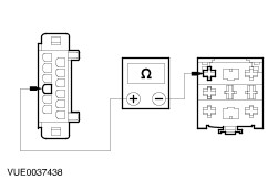
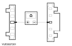
| | 3 Measure the resistance between the speed control module C63 pin 11, (BK/RD), harness side and steering wheel switch control module C607 pin 5, (BN), harness side. |
| | Is the resistance less than 5 ohms? Yes No |
| A10: CHECK THE STEERING WHEEL SWITCH CONTROL MODULE TO SPEED CONTROL MODULE CIRCUIT FOR OPEN |
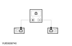
| | 1 Measure the resistance between the steering wheel switch control module C608 pin 4, (BK/WH), harness side and speed control module C63 pin 8, (BK/WH), harness side. |
| | Is the resistance less than 5 ohms? Yes No REPAIR the circuit. TEST the system for normal operation. |
| A11: CHECK THE STEERING WHEEL SWITCH CONTROL MODULE TO SPEED CONTROL MODULE SET CIRCUIT FOR OPEN |
| | 1 Measure the resistance between the steering wheel switch control module C608 pin 8, (RD), harness side and speed control module C63 pin 4, (RD), harness side. |
| | Is the resistance less than 5 ohms? Yes No REPAIR the circuit. TEST the system for normal operation. |
| A12: CHECK THE STEERING WHEEL SWITCH CONTROL MODULE TO SPEED CONTROL MODULE RES CIRCUIT FOR OPEN |
| | 1 Measure the resistance between the steering wheel switch control module C607 pin 7, (BU), harness side and speed control module C63 pin 10, (BU), harness side. |
| | Is the resistance less than 5 ohms? Yes No REPAIR the circuit. TEST the system for normal operation. |
| A13: CHECK THE SPEED CONTROL MODULE TO SPEED CONTROL VACUUM PUMP CIRCUITS FOR OPEN |
| | 1 Disconnect speed control vacuum pump C65. |
| | 2 Measure the resistance between the following speed control module C63 pins, harness side and speed control vacuum pump C65 pins, harness side: - C63, pin 6 (BN/RD) to C65, pin 2 (BN/RD).
- C63, pin 7 (BK) to C65, pin 3 (BK).
- C63, pin 12 (BU/WH) to C65, pin 1 (BU/WH).
|
| | Are the resistances less than 5 ohms? Yes No REPAIR the circuit(s). TEST the system for normal operation. |
| A14: CHECK THE SPEED CONTROL MODULE GROUND CIRCUITS FOR OPEN |
| | 1 Measure the resistance between the speed control module C63 pin 1, (BN), harness side and ground and pin 5, (BN), harness side and ground. |
| | Are the resistances less than 5 ohms? Yes No REPAIR the circuit(s). TEST the system for normal operation. |
| A15: CHECK THE SPEED SIGNAL TO THE SPEED CONTROL MODULE |
WARNING:The following steps require the vehicle wheels to rotate freely. Failure to follow these instructions may result in personal injury. |
| | 1 |
| | 2 Ignition switch in position III. |
| | 3 Select a low gear and allow the wheels rotate. |
| | 4 Measure the frequency between the speed control module C63 pin 9, (VT), harness side and ground. |
| | Is the frequency 40Hz at 32km/h (20mph) and 60Hz at 50km/h (30mph)? Yes No REPAIR the circuit. TEST the system for normal operation. |
| A16: CHECK THE SPEED CONTROL VACUUM PUMP FOR CORRECT OPERATION |
| | 1 Check the speed control vacuum pump for correct operation, refer to the speed control vacuum pump component test in the section. |
| | Is the speed control vacuum pump operation OK? Yes INSTALL a new steering wheel switch control module. TEST the system for normal operation. If the steering wheel switch control module is OK, INSTALL a new speed control module. TEST the system for normal operation. If the speed control module is OK, INSTALL a new drivers airbag module. REFER to Section 501-20 Supplemental Restraint System. TEST the system for normal operation. No INSTALL a new speed control vacuum pump. TEST the system for normal operation. |
| A17: CHECK FOR POWER TO THE STEERING WHEEL SWITCH CONTROL MODULE |
| | 1 Ignition switch in position 0. |
| | 2 Disconnect steering wheel switch control module C607 and C608. |
| | 3 Ignition switch in position II. |
| | 4 Measure the voltage between the steering wheel switch control module C607 pin 3, (BK/YE), harness side and ground and steering wheel switch control module C607 pin 4, (RD/WH), harness side and ground. |
| | Are the voltages greater than 10 volts? Yes No REPAIR the circuit. TEST the system for normal operation. |
| A18: CHECK THE STEERING WHEEL SWITCH CONTROL MODULE FOR GROUND |
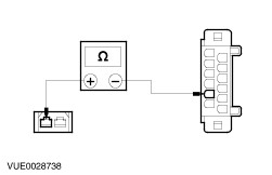
| | 1 Measure the resistance between the steering wheel switch control module C607 pin 1, (BN), harness side and ground. |
| | Is the resistance less than 5 ohms? Yes No REPAIR the circuit. TEST the system for normal operation. |
| A19: CHECK THE STEERING WHEEL SWITCHES FOR POWER |
| | 1 Disconnect clockspring C546. |
| | 2 Measure the voltage between the clockspring C546 pin 3, (BK/YE), harness side and ground. |
| | Is the voltage greater than 10 volts? Yes No REPAIR the circuit. TEST the system for normal operation. |
| A20: CHECK THE CLOCKSPRING FOR OPEN CIRCUIT |
| | 1 Measure the resistance between the clockspring C546 pin 3, component side and the clock spring to drivers airbag module connector pin 3, component side. |
| | Is the resistance less than 1 ohm? Yes INSTALL a new steering wheel switch control module. TEST the system for correct operation. If the steering wheel switch control module is OK, INSTALL a new drivers airbag module. REFER to Section 501-20 Supplemental Restraint System. TEST the system for correct operation. No INSTALL a new clockspring. TEST the system for normal operation. |
| A21: CHECK THE STEERING WHEEL SPEED CONTROL SWITCH CIRCUIT FOR POWER |
| | 1 Ignition switch in position 0. |
| | 2 Disconnect steering wheel switch control module C607 and C608. |
| | 3 Ignition switch in position II. |
| | 4 Operate the steering wheel speed control ON switch. |
| | 5 Measure the voltage between the steering wheel switch control module C608 pin 4, (BK/WH),harness side and ground. |
| | Is the voltage greater than 10 volts? Yes INSTALL a new steering wheel switch control module. TEST the system for normal operation. No |
| A22: CHECK THE STEERING WHEEL SPEED CONTROL SWITCH CIRCUIT FOR OPEN |
| | 1 Ignition switch in position 0. |
| | 2 Disconnect clockspring C546. |
| | 3 Measure the resistance between the steering wheel switch control module C608 pin 4, (BK/WH), harness side and clockspring C546 pin 4, BK/WH), harness side. |
| | Is the resistance less than 5 ohms? Yes No REPAIR the circuit. TEST the system for normal operation. |
| A23: CHECK THE CLOCK SPRING FOR OPEN |
| | 1 |
| | 2 Measure the resistance between the clock spring C546 pin 4, component side and clock spring to drivers airbag module connector pin 4 component side. |
| | Is the resistance less than 1 ohm? Yes No INSTALL a new clockspring. TEST the system for normal operation. |
| A24: CHECK THE SPEED CONTROL CLUTCH PEDAL DEACTIVATOR SWITCH FOR OPEN |
| | 1 Disconnect speed control brake pedal deactivator switch C295. |
| | 2 Measure the resistance between the speed control brake pedal deactivator switch C295 pin 1, (BK), harness side and speed control module C63 pin 11, (BK/RD), harness side. |
| | Is the resistance less than 5 ohms? Yes No |
| A25: CHECK THE SPEED CONTROL BRAKE PEDAL DEACTIVATOR SWITCH TO STEERING WHEEL SWITCH CONTROL MODULE CIRCUIT FOR OPEN |
| | 1 Measure the resistance between the speed control brake pedal deactivator switch C295 pin 2, (BN), harness side and steering wheel switch control module C607 pin 5, (BN), harness side. |
| | Is the resistance less than 5 ohms? Yes INSTALL a new speed control brake pedal deactivator switch. TEST the system for normal operation. No REPAIR the circuit. TEST the system for normal operation. |
| A26: CHECK THE SPEED CONTROL BRAKE PEDAL DEACTIVATOR SWITCH TO CLUTCH PEDAL DEACTIVATOR SWITCH CIRCUIT FOR OPEN |
| | 1 Disconnect speed control clutch pedal deactivator switch C173. |
| | 2 Measure the resistance between the speed control brake pedal deactivator switch C295 pin 1, (BK), harness side and speed control clutch pedal deactivator switch C173 pin 2, (BK), harness side. |
| | Is the resistance less than 5 ohms? Yes No REPAIR the circuit. TEST the system for normal operation. |
| A27: CHECK THE SPEED CONTROL CLUTCH PEDAL DEACTIVATOR SWITCH TO SPEED CONTROL MODULE CIRCUIT FOR OPEN |
| | 1 Measure the resistance between the speed control module C63 pin 11, (BK/RD), harness side and speed control clutch pedal deactivator switch C173 pin 1, (BK/RD), harness side. |
| | Is the resistance less than 5 ohms? Yes INSTALL a new speed control clutch pedal deactivator switch. TEST the system for normal operation. No REPAIR the circuit. TEST the system for normal operation. |
| A28: CHECK THE SPEED CONTROL BRAKE PEDAL DEACTIVATOR SWITCH TO STEERING WHEEL SWITCH CONTROL MODULE CIRCUIT FOR OPEN |
| | 1 Disconnect speed control brake pedal deactivator switch C295. |
| | 2 Measure the resistance between the speed control brake pedal deactivator switch C295 pin 2, (BN), harness side and steering wheel switch control module C607 pin 5, (BN), harness side. |
| | Is the resistance less than 5 ohms? Yes No REPAIR the circuit. TEST the system for normal operation. |
| A29: CHECK THE SPEED CONTROL BRAKE PEDAL DEACTIVATOR SWITCH TO SPEED CONTROL MODULE CIRCUIT FOR OPEN |
| | 1 Measure the resistance between the speed control module C63 pin 11, (BK/RD), harness side and speed control brake pedal deactivator switch C295 pin 1, (BK/RD), harness side. |
| | Is the resistance less than 5 ohms? Yes INSTALL a new speed control brake pedal deactivator switch. TEST the system for normal operation. No REPAIR the circuit. TEST the system for normal operation. |