| PINPOINT TEST A : THE SPEED CONTROL IS INOPERATIVE |
| TEST CONDITIONS | DETAILS/RESULTS/ACTIONS |
| A1: CHECK THE PEDAL POSITION SWITCHES AND SENSOR USING WDS |
| | 1 Using WDS check the operation of the clutch pedal position (CPP) switch (if equipped), brake pedal position (BPP) switch and APP sensor. |
| | Are the pedal position switches and sensor working correctly? Yes No The CPP switch is inoperative, GO to A6. . The BPP switch is inoperative (1.9L diesel engine), GO to A8. . The BPP switch is inoperative (2.8L engine), GO to A10. . The APP sensor is inoperative (1.9L diesel engine), GO to A12. . The APP sensor is inoperative (2.8L engine), GO to A13. . |
| A2: CHECK POWER TO THE SPEED CONTROL SWITCH |
| | 1 Disconnect Speed Control Switch C263. |
| | 2 Ignition switch in position II. |
| | 3 Measure the voltage between the speed control switch C263 pin 6, (BK) (1.9L diesel engine), pin 6, (BK/YE) (2.8L engine), harness side and ground. |
| | Is the voltage greater than 10 volts? Yes No REPAIR the circuit. TEST the system for normal operation. |
| A3: CHECK THE SPEED CONTROL SWITCH OPERATION |
| | 1 Ignition switch in position 0. |
| | 2 Check the speed control switch for correct operation, refer to the speed control switch component test in the section. |
| | Is the speed control switch operation ok? Yes Vehicles with 1.9L diesel engine, GO to A4. . Vehicles with 2.8L engine, GO to A5. . No INSTALL a new steering column multifuction switch. TEST the system for normal operation. |
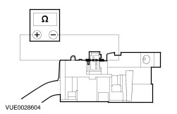
| A4: CHECK THE SPEED CONTROL CIRCUITS FOR OPEN |
| | 1 Disconnect PCM C52b. |
| | 2 Measure the resistance between the following speed control switch C263 pins, harness side and PCM C52b pins, harness side: - C263, pin 2 (BU/GY) to C52b, pin 45 (BU/GY).
- C263, pin 3 (RD) to C52b, pin 44 (RD).
- C263, pin 4 (BK/WH) to C52b, pin 14 (BK/WH).
- C263, pin 5 (GY) to C52b, pin 46 (GY).
- C263, pin 7 (BK/WH) to C52b, pin 14 (BK/WH).
|
| | Are the resistances less than 5 ohms? Yes No REPAIR the circuit(s). TEST the system for normal operation |
| A5: CHECK THE SPEED CONTROL SWITCH TO PCM CIRCUITS FOR OPEN |
| | 1 Disconnect PCM C51b. |
| | 2 Measure the resistance between the following speed control switch C263 pins, harness side and PCM C51b pins, harness side: - C263, pin 2 (BU) to C51b, pin 75 (BU).
- C263, pin 3 (BU/BN) to C51b, pin 57 (BU/BN).
- C263, pin 4 (BK/WH) to C51b, pin 38 (BK/WH).
- C263, pin 5 (BK/YE) to C51b, pin 76 (BK/YE).
- C263, pin 7 (BK/WH) to C51b, pin 38 (BK/WH).
|
| | Are the resistances less than 5 ohms? Yes No REPAIR the circuit(s). TEST the system for normal operation |
| A6: CHECK POWER TO THE CLUTCH PEDAL POSITION SWITCH |
| | 1 Disconnect CPP Switch C356 (1.9L diesel engine). |
| | 2 Disconnect CPP Switch C154 (2.8L engine). |
| | 3 Ignition switch in position II. |
| | 4 Measure the voltage between the CPP switch C356 pin 1, (BK/YE) (1.9L diesel engine), harness side and ground or C154 pin 1, (BK) (2.8L engine), harness side and ground |
| | Is the voltage greater than 10 volts? Yes No REPAIR the circuit. TEST the system for normal operation. |
| A7: CHECK THE CPP SWITCH CIRCUIT FOR OPEN |
| | 1 Ignition switch in position 0. |
| | 2 Disconnect PCM C52b (1.9L diesel engine). |
| | 3 Disconnect PCM C51b (2.8L engine). |
| | 4 Measure the resistance between the CPP switch C356 pin 2, (WH/RD), harness side and PCM C52b pin 66, (WH/RD) (1.9L diesel engine), harness side or C154 pin 2, (BK/WH), harness side and PCM C51b pin 39, (BK/WH) (2.8L engine), harness side. |
| | Is the resistance less than 5 ohms? Yes CHECK the CPP switch, refer to the wiring diagrams for additional information. INSTALL a new CPP switch as necessary. If the CPP switch is OK, INSTALL a new PCM. REFER to Powertrain Control Module (PCM) in this section. TEST the system for normal operation. No REPAIR the circuit. TEST the system for normal operation. |
| A8: CHECK POWER TO THE BPP SWITCH |
| | 1 Disconnect BPP Switch C354. |
| | 2 Ignition switch in position II. |
| | 3 Measure the voltage between the BPP switch C354 pin 1, (RD/YE), harness side and ground and pin 2, (BK/YE), harness side and ground. |
| | Are the voltages greater than 10 volts? Yes No REPAIR the circuit(s). TEST the system for normal operation. |
| A9: CHECK THE BPP SWITCH CIRCUITS FOR OPEN |
| | 1 Ignition switch in position 0. |
| | 2 Disconnect PCM C52b. |
| | 3 Measure the resistance between the BPP switch C354, harness side and PCM C52b, harness side, between the following pins: - C354, pin 3 (WH/YE) to C52b, pin 65 (WH/YE).
- C354, pin 4 (BK/RD) to C52b, pin 32 (BK/RD).
|
| | Are the resistances less than 5 ohms? Yes CHECK the BPP switch, refer to the wiring diagrams for additional information. INSTALL a new BPP switch as necessary. If the BPP switch is OK, INSTALL a new PCM. REFER to Powertrain Control Module (PCM) in this section. TEST the system for normal operation. No REPAIR the circuit(s). TEST the system for normal operation. |
| A10: CHECK POWER TO THE BPP SWITCH |
| | 1 Disconnect BPP switch C153. |
| | 2 Ignition switch in position II. |
| | 3 Measure the voltage between the BPP switch C153 pin 1, (RD/YE), harness side and ground and pin 2, (BK), harness side and ground. |
| | Are the voltages greater than 10 volts? Yes No REPAIR the circuit(s). TEST the system for normal operation. |
| A11: CHECK THE BPP SWITCH CIRCUITS FOR OPEN |
| | 1 Ignition switch in position 0. |
| | 2 Disconnect PCM C51b. |
| | 3 Measure the resistance between the BPP switch C153, harness side and PCM C51b, harness side, between the following pins: - C153, pin 3 (WH/YE) to C51b, pin 55 (WH/YE).
- C153, pin 4 (BK/RD) to C51b, pin 56 (BK/RD).
|
| | Are the resistances less than 5 ohms? Yes CHECK the BPP switch, refer to the wiring diagrams for additional information. INSTALL a new BPP switch as necessary. If the BPP switch is OK, INSTALL a new PCM. REFER to Powertrain Control Module (PCM) in this section. TEST the system for normal operation. No REPAIR the circuit(s). TEST the system for normal operation. |
| A12: CHECK THE APP SENSOR CIRCUITS FOR OPEN |
| | 1 Disconnect APP sensor C56. |
| | 2 Disconnect PCM C52b. |
| | 3 Measure the resistance between the following APP sensor C56 pins, harness side and PCM C52b pins, harness side: - C56, pin 1 (GN/BN) to C52b, pin 63 (GN/BN).
- C56, pin 2 (RD/BU) to C52b, pin 12 (RD/BU).
- C56, pin 3 (GY/RD) to C52b, pin 50 (GY/RD).
- C56, pin 4 (WH/BU) to C52b, pin 69 (WH/BU).
- C56, pin 5 (BU/GY) to C52b, pin 36 (BU/GY).
- C56, pin 6 (BN/BU) to C52b, pin 51 (BN/BU).
|
| | Are the resistances less than 5 ohms? Yes INSTALL a new APP sensor. TEST the system for normal operation. If the concern persists, INSTALL a new PCM. No REPAIR the circuit(s). TEST the system for normal operation. |
| A13: CHECK THE APP SENSOR CIRCUITS FOR OPEN |
| | 1 Disconnect APP sensor C56. |
| | 2 Disconnect PCM C51b. |
| | 3 Measure the resistance between the following APP sensor C56 pins, harness side and PCM C51b pins, harness side: - C56, pin 1 (WH) to C51b, pin 72 (WH).
- C56, pin 2 (YE) to C51b, pin 73 (YE).
- C56, pin 3 (RD) to C51b, pin 36 (RD).
- C56, pin 4 (VT) to C51b, pin 35 (VT).
- C56, pin 5 (GN) to C51b, pin 33 (GN).
- C56, pin 6 (GY) to C51b, pin 34 (GY).
|
| | Are the resistances less than 5 ohms? Yes INSTALL a new APP sensor. TEST the system for normal operation. If the concern persists, INSTALL a new PCM. No REPAIR the circuit(s). TEST the system for normal operation. |