| Diagnosis and Testing Refer to Wiring Diagrams Section 412-00, for schematic and connector information. Special Tool(s) | | Terminal Probe Kit 418-S035 | General Equipment Digital Multimeter (compatible with K-type thermocouple) Worldwide Diagnostic System (WDS) Refrigerant Center Temperature Sensor - Fluke 80 PK-8 (FSE number 260 4102 001 07) Inspection and Verification - Verify the customer concern.
- Visually inspect for obvious signs of mechanical or electrical damage.
Visual Inspection Chart | Mechanical | Electrical | - Drive belt
- Coolant level
- Refrigerant lines
- Condenser
- Compressor
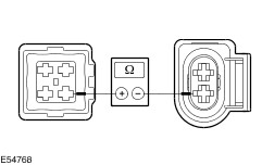
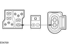
| - Fuse(s)
- Wiring harness
- Electrical connectors
| - If an obvious cause for an observed or reported concern is found, CORRECT the cause (if possible) before proceeding to the next step. TEST the system for normal operation.
- If the cause is not visually evident, CHECK the powertrain control module (PCM) and the automatic temperature control (ATC) module using the WDS. If an error code is displayed, CORRECT the cause using the WDS. TEST the system for normal operation.
- If there is no error code displayed, VERIFY the symptom and REFER to the Symptom Chart.
- After the test or elimination of a concern, CHECK all modules that are installed on the vehicle by using the WDS. ERASE all error codes. CARRY a road test of the vehicle. CHECK all modules again.
Refrigerant Circuit - Quick Check WARNING:The air conditioning (A/C) systems is filled with refrigerant R134a. Observe "Health and Safety Precautions".
REFER to: Health and Safety Precautions (100-00 General Information, Description and Operation).
NOTE:All readings should to be taken at normal ambient temperature with the engine at normal operation temperature. Refrigerant Circuit Check WARNING:Under certain circumstances, refrigerant lines and A/C components may be extremely hot or cold. Exercising care, touch the refrigerant lines or A/C components in order to check this. Failure to follow these instructions may result in personal injury. During operation the A/C system, the following conditions shows be apparent: - The refrigerant line from the A/C compressor to the A/C condenser should be hot.
- The refrigerant line from the A/C condenser to the thermostatic expansion valve should be warm, but cooler than the previously mentioned refrigerant line.
- Determine the difference in temperature upstream and downstream of the A/C condenser by measuring the temperatures. The temperature difference should be more than 20°, depending on the ambient temperature. If the temperature difference is less, check the A/C condenser for contamination or damage to the fins as well as operation of the radiator fan.
- The refrigerant line between the thermostatic expansion valve and the evaporator core must be cold from the installation position of the thermostatic expansion valve. Depending on the weather, the refrigerant line may also be iced up on the outside.
- The refrigerant line between the evaporator core and the A/C compressor should be cold.
Evaporator Outlet Temperature Test In order to check the A/C output, the temperature of the evaporator core outlet line must be measured. The following preparations must be taken for this purpose: - Open all windows.
- Set the air distribution to the defrost/instrument panel position and open all air ducts.
- DO NOT switch on recirculated air.
- Select lowest blower switch setting.
- Select lowest temperature setting.
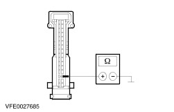
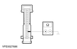
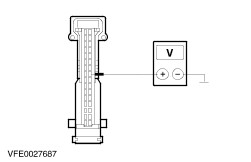
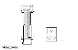
NOTE:The temperature measurements cannot be carried out using a non-contact thermometer. Incorrect measurements result owing to surface reflection. Connect the temperature sensor (Fluke 80 PK-8) to the evaporator core outlet line. The temperature sensor must be positioned as closely as possible to the evaporator core. Connect the temperature sensor to the digital multimeter. Start the engine and allow it to run at idle speed for several minutes. Switch on the A/C system. After three minutes, measure the surface temperature of the evaporator core outlet line. If the temperature measured is 5° C (Vehicles with dual A/C system: 7° C) or lower, the A/C system is OK. If the temperature is higher, the A/C system may be under-filled. For further information
REFER to: Air Conditioning (A/C) System Recovery, Evacuation and Charging (412-00 Climate Control System - General Information, General Procedures).
Frequent faults and their causes Should a customer express concern about poor cooling performance of the A/C system it must be made sure that actuation of the temperature door(s) is functioning correctly. - No or poor cooling performance:
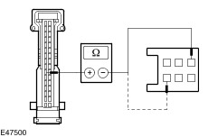
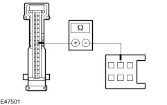
- Blockage or restriction in one of the refrigerant lines or in the receiver/drier: By comparing temperatures at the refrigerant lines or at the receiver/drier, the location of the blockage or restriction can easily be identified. The blockage or restriction is located at the point where the temperature difference is identified. Note: A temperature difference in the area of the thermostatic expansion valve is normal. Once the location of the blockage or restriction has been detected, check the relevant component and install new parts if necessary. - Sudden poor cooling performance (after the A/C system has been switched off for approximately 5 minutes, the cooling performance returns to normal):
- Thermostatic expansion valve iced-up. The cause for an iced-up thermostatic expansion valve is moisture in the system. In order to ensure that moisture is completely removed from the refrigerant circuit, evacuation time must be extended to 2-3 hours and a new receiver/drier must be installed. For further information
REFER to: Air Conditioning (A/C) System Recovery, Evacuation and Charging (412-00 Climate Control System - General Information, General Procedures).
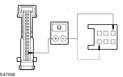
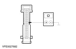
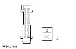
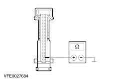
Symptom Chart Symptom Chart | Symptom | Possible Sources | Action | | Front blower motor is inoperative - Vehicles with automatic temperature control (ATC) | * Fuse(s). * Circuit(s). * Blower cutoff relay. * Front blower motor. * Front heater blower control unit. * ATC module. | * | | Front blower motor is inoperative - Vehicles without automatic temperature control (ATC) | * Fuse(s). * Circuit(s). * Front blower motor. * Heater blower switch. * Heater blower series resistor. * Blower cutoff relay. | * | | Rear blower motor is inoperative - Vehicles with automatic temperature control (ATC) | * Circuit(s). * Rear blower motor. * Rear heater blower control unit. * ATC module. | * | | Rear blower motor is inoperative - Vehicles without automatic temperature control (ATC) | * Fuse(s). * Circuit(s). * Rear blower motor. * Heater blower switch. * Control module, second heat exchanger. * Heater blower series resistor, second heat exchanger. | * | | Air Conditioning (A/C) system is inoperative - Vehicles with 2.0L or 2.3L engine | * Fuse(s). * Circuit(s). * Heater blower switch. * A/C compressor clutch. * A/C compressor clutch diode. * Powertrain control module (PCM). * A/C wide open throttle (WOT) relay. * Automatic temperature control (ATC) module. * De-icing switch. * 3-way pressure switch. * Outside air temperature switch. * Automatic transmission module. * Quantity of refrigerant. | * | | Air Conditioning (A/C) system is inoperative - Vehicles with 2.8L or diesel engine , except 96 kW (130 PS) diesel engine | * Fuse(s). * Circuit(s). * Heater blower switch. * A/C compressor clutch. * A/C compressor clutch module. * Powertrain control module (PCM). * Automatic temperature control (ATC) module. * 3-way pressure switch. * Outside air temperature switch. * Cooling fan run-on thermo switch. * Quantity of refrigerant. | * | | Air Conditioning (A/C) system is inoperative - Vehicles with 96 kW (130 PS) diesel engine | * Fuse(s). * Circuit(s). * Heater blower switch. * A/C compressor clutch. * A/C compressor clutch module. * Powertrain control module (PCM). * Automatic temperature control (ATC) module. * A/C pressure transducer sensor. * Outside air temperature switch. * Quantity of refrigerant. | * | | Fresh air/recirculation air flap is inoperative | * Circuit(s). * Fresh air/recirculation air door motor. * Fresh air/recirculation air flap. * Heater blower switch. * ATC module. | * | | Front temperature flap is inoperative | * Circuit(s). * Temperature flap unit. * Heater blower switch. * ATC module. | * | | Rear temperature flap is inoperative | * Circuit(s). * Control module, second heat exchanger. * Control motor, second heat exchanger. * Heater blower switch. * Rear temperature flap unit. * ATC module. | * | | Air distribution is inoperative | * Circuit(s). * Central vent flap unit. * Central flap unit. * Rear central flap unit. * ATC module. * Heater blower switch. | * | | Front in-vehicle temperature sensor circuit failure - Vehicles with automatic temperature control (ATC) | * Circuit(s). * Front in-vehicle temperature sensor. * Automatic temperature control (ATC) module. | * | | Rear in-vehicle temperature sensor circuit failure - Vehicles with automatic temperature control (ATC) | * Circuit(s). * Rear in-vehicle temperature sensor. * Automatic temperature control (ATC) module. | * | | Outside air temperature sensor circuit failure - Vehicles with automatic temperature control (ATC) | * Circuit(s). * Outside air temperature sensor. * Automatic temperature control (ATC) module. | * | | Sunload sensor circuit failure - Vehicles with automatic temperature control (ATC) | * Circuit(s). * Sunload sensor. * Automatic temperature control (ATC) module. | * | | Engine coolant temperature sensor A/C circuit failure - Vehicles with automatic temperature control (ATC) | * Circuit(s). * Engine coolant temperature sensor A/C. * Automatic temperature control (ATC) module. | * | | Climate control assembly inoperative - Vehicles with automatic temperature control (ATC) | * Fuse(s). * Circuit(s). * Automatic temperature control (ATC) module. | * | | Condensed water from the air conditioning system in the footwell | * Air conditioning outlet pipe not connected to the heater. * Air conditioning outlet pipe incorrectly routed through the body panel. * Air conditioning outlet pipe bent or blocked. | * Check that the air conditioning outlet pipe is routed correctly. | Pinpoint Tests | PINPOINT TEST A : BLOWER MOTOR FRONT IS INOPERATIVE - VEHICLES WITH AUTOMATIC TEMPERATURE CONTROL (ATC) | | TEST CONDITIONS | DETAILS/RESULTS/ACTIONS | | A1: CHECK THE EQUIPMENT OF THE VEHICLE | | | 1 Check if the vehicle is equipped with a programmable fuel fired booster heater. | | | Is the vehicle equipped with a programmable fuel fired booster heater? Yes - Vehicles built up to 05/2002: GO to A4. - Vehicles built 05/2002 onwards: GO to A6. No | | A2: CHECK FUSE F22 | | | 1 Ignition switch in position 0. | | | 2 CHECK fuse F22 (CJB). | | | Is the fuse OK? Yes No INSTALL a new fuse F22 (30 A). TEST the system for normal operation. If the fuse blows again, LOCATE and REPAIR the short circuit using the wiring diagrams. | | A3: CHECK THE VOLTAGE AT FUSE F22 | | | 1 Connect fuse F22 (CJB). | | | 2 Ignition switch in position II. | | | 3 Measure the voltage between fuse F22 (30 A) and ground. | | | Is battery voltage indicated? Yes No REPAIR the power supply of fuse F22 using the wiring diagrams. TEST the system for normal operation. | | A4: CHECK FUSE F33 | | | 1 Ignition switch in position 0. | | | 2 CHECK fuse F33 (CJB). | | | Is the fuse OK? Yes No INSTALL a new fuse F33 (30 A) (Vehicle built between 11/2001 and 05/2002: 10 A). TEST the system for normal operation. If the fuse blows again, LOCATE and REPAIR the short circuit using the wiring diagrams. | | A5: CHECK THE VOLTAGE AT FUSE F33 | | | 1 Connect fuse F33 (CJB). | | | 2 Ignition switch in position II. | | | 3 Measure the voltage between fuse F33 (30 A) (Vehicle built between 11/2001 and 05/2002: 10 A) and ground. | | | Is battery voltage indicated? Yes No REPAIR the power supply of fuse F33 using the wiring diagrams. TEST the system for normal operation. | | A6: CHECK FUSE F77 | | | 1 Ignition switch in position 0. | | | 2 CHECK fuse F77 (fuse holder). | | | Is the fuse OK? Yes No INSTALL a new fuse F77 (30 A). TEST the system for normal operation. If the fuse blows again, LOCATE and REPAIR the short circuit using the wiring diagrams. | | A7: CHECK THE VOLTAGE AT FUSE F77 | | | 1 Connect fuse F77 (fuse holder). | | | 2 Ignition switch in position II. | | | 3 Measure the voltage between fuse F77 (30 A) and ground. | | | Is battery voltage indicated? Yes No REPAIR the power supply of fuse F77 using the wiring diagrams. TEST the system for normal operation. | | A8: CHECK THE VOLTAGE AT THE FRONT BLOWER MOTOR | | | 1 Ignition switch in position 0. | | | 2 Disconnect front blower motor C213. | | | 3 Ignition switch in position II. | | | 4 Measure the voltage between the front blower motor, connector C213, pin 2 (RD/WH), harness side and ground. | | | Is battery voltage indicated? Yes No - Vehicles without programmable fuel fired booster heater: GO to A15. - Vehicles with programmable fuel fired booster heater: GO to A9. | | A9: CHECK THE VOLTAGE AT THE BLOWER CUTOFF RELAY - PIN 2 | | | 1 Ignition switch in position 0. | | | 2 Disconnect blower cutoff relay C22 (CJB). | | | 3 Measure the voltage between the blower cutoff relay, socket C22, pin 2 (RD), harness side and ground. | | | Is battery voltage indicated? Yes No | | A10: CHECK THE CIRCUIT BETWEEN BLOWER CUTOFF RELAY AND CJB FOR OPEN - VEHICLES BUILT UP TO 05/2002 | | | 1 Disconnect CJB C8. | | | 2 Measure the resistance between the blower cutoff relay, connector C22, pin 2 (RD), harness side and CJB, connector C8, pin 66 (RD), harness side. | | | Is the resistance less than 2 ohms? Yes CHECK the CJB. If necessary INSTALL a new CJB. TEST the system for normal operation. No LOCATE and REPAIR the open in circuit between blower cutoff relay and CJB using the wiring diagrams. TEST the system for normal operation. | | A11: CHECK THE CIRCUIT BETWEEN BLOWER CUTOFF RELAY AND FUSE HOLDER FOR OPEN - VEHICLES BUILT 05/2002 ONWARDS | | | 1 Disconnect fuse holder C33. | | | 2 Measure the resistance between the blower cutoff relay, connector C22, pin 2 (RD), harness side and fuse holder, connector C33, pin 4 (RD), harness side. | | | Is the resistance less than 2 ohms? Yes CHECK the fuse holder. If necessary INSTALL a new fuse holder. TEST the system for normal operation. No LOCATE and REPAIR the open in circuit between blower cutoff relay and fuse holder using the wiring diagrams. TEST the system for normal operation. | | A12: CHECK THE VOLTAGE AT THE BLOWER CUTOFF RELAY - PIN 4 | | | 1 Ignition switch in position II. | | | 2 Measure the voltage between the blower cutoff relay, socket C22, pin 4 (BK/YE), harness side and ground. | | | Is battery voltage indicated? Yes No LOCATE and REPAIR the open in circuit between blower cutoff relay and splice S44 using the wiring diagrams. TEST the system for normal operation. | | A13: CHECK THE GROUND CONNECTION OF THE BLOWER CUTOFF RELAY | | | 1 Ignition switch in position 0. | | | 2 Measure the resistance between the blower cutoff relay, socket C22, pin 6 (BN), harness side and ground. | | | Is the resistance less than 2 ohms? Yes No LOCATE and REPAIR the open in circuit between blower cutoff relay and splice S85 using the wiring diagrams. TEST the system for normal operation. | | A14: CHECK THE CIRCUIT BETWEEN FRONT BLOWER MOTOR AND BLOWER CUTOFF RELAY FOR OPEN | | | 1 Measure the resistance between the front blower motor, connector C213, pin 2 (RD/WH), harness side and blower cutoff relay, socket C22, pin 8 (RD/WH), harness side. | | | Is the resistance less than 2 ohms? Yes INSTALL a new blower cutoff relay. TEST the system for normal operation. No LOCATE and REPAIR the open in circuit between front blower motor and blower cutoff relay using the wiring diagrams. TEST the system for normal operation. | | A15: CHECK THE CIRCUIT BETWEEN FRONT BLOWER MOTOR AND CJB FOR OPEN | | | 1 Ignition switch in position 0. | | | 2 Disconnect CJB C8. | | | 3 Measure the resistance between the front blower motor, connector C213, pin 2 (RD/WH), harness side and CJB, connector C8, pin 44 (RD/WH), harness side. | | | Is the resistance less than 2 ohms? Yes CHECK the CJB. If necessary INSTALL a new CJB. TEST the system for normal operation. No LOCATE and REPAIR the open in circuit between front blower motor and CJB using the wiring diagrams. TEST the system for normal operation. | | A16: CHECK THE GROUND CONNECTION OF THE HEATER BLOWER CONTROL UNIT | | | 1 Ignition switch in position 0. | | | 2 Disconnect heater blower control unit C209. | | | 3 Measure the resistance between the heater blower control unit, connector C209, pin 3 (BN), harness side and ground. | | | Is the resistance less than 2 ohms? Yes No LOCATE and REPAIR the open in circuit between heater blower control unit and ground G9 (Right-hand drive vehicles: ground G6) using the wiring diagrams. TEST the system for normal operation. | | A17: CHECK THE FRONT BLOWER MOTOR | | | 1 Connect front blower motor C213. | | | 2 Connect a fused jumper wire (30 A) at the heater blower control unit, connector C209, between pin 2 (BK/RD) and pin 3 (BN), harness side. | | | 3 Ignition switch in position II. | | | Does the front blower motor operate? Yes No | | A18: CHECK THE CIRCUIT BETWEEN FRONT BLOWER MOTOR AND HEATER BLOWER CONTROL UNIT FOR OPEN | | | 1 Ignition switch in position 0. | | | 2 Disconnect front blower motor C213. | | | 3 Measure the resistance between the front blower motor, connector C213, pin 1 (BK/RD), harness side and the heater blower control unit, connector C209, pin 2 (BK/RD), harness side. | | | Is the resistance less than 2 ohms? Yes INSTALL a new front blower motor. TEST the system for normal operation. No LOCATE and REPAIR the open in circuit between blower motor and heater blower control unit using the wiring diagrams. TEST the system for normal operation. | | A19: CHECK THE CIRCUIT BETWEEN HEATER BLOWER CONTROL UNIT AND AUTOMATIC TEMPERATURE CONTROL (ATC) MODULE FOR OPEN | | | 1 Ignition switch in position 0. | | | 2 Disconnect ATC module C193. | | | 3 Measure the resistance between the heater blower control unit, connector C209, pin 1 (WH/BU), harness side and ATC module, connector C193, pin 7 (WH/BU), harness side. | | | Is the resistance less than 2 ohms? Yes No LOCATE and REPAIR the open in circuit between heater blower control unit and ATC module using the wiring diagrams. TEST the system for normal operation. | | A20: CHECK THE CIRCUIT BETWEEN HEATER BLOWER CONTROL UNIT AND ATC MODULE FOR SHORT TO POWER | | | 1 Ignition switch in position II. | | | 2 Measure the voltage between the ATC module, connector C193, pin 7 (WH/BU), harness side and ground. | | | Is any voltage indicated? Yes LOCATE and REPAIR the short to power in circuit between heater blower control unit and ATC module using the wiring diagrams. TEST the system for normal operation. No | | A21: CHECK THE CIRCUIT BETWEEN HEATER BLOWER CONTROL UNIT AND ATC MODULE FOR SHORT TO GROUND | | | 1 Ignition switch in position 0. | | | 2 Measure the resistance between the ATC module, connector C193, pin 7 (WH/BU), harness side and ground. | | | Is the resistance greater than 10,000 ohms? Yes No LOCATE and REPAIR the short to ground in circuit between heater blower control unit and ATC module using the wiring diagrams. TEST the system for normal operation. | | A22: CHECK THE CIRCUIT BETWEEN FRONT BLOWER MOTOR AND ATC MODULE FOR OPEN | | | 1 Disconnect front blower motor C213. | | | 2 Measure the resistance between the front blower motor, connector C213, pin 1 (BK/RD), harness side and the ATC module, connector C193, pin 20 (Vehicles built 11/2002 onwards: pin 19) (BK/RD), harness side. | | | Is the resistance less than 2 ohms? Yes INSTALL a new heater blower control unit. TEST the system for normal operation. If the system is still inoperative, CHECK the ATC module, if necessary INSTALL a new ATC module. TEST the system for normal operation. No LOCATE and REPAIR the open in circuit between Splice S35 and ATC module using the wiring diagrams. TEST the system for normal operation. | | PINPOINT TEST B : FRONT BLOWER MOTOR IS INOPERATIVE - VEHICLES WITHOUT AUTOMATIC TEMPERATURE CONTROL (ATC) | | TEST CONDITIONS | DETAILS/RESULTS/ACTIONS | | B1: DETERMINE THE FAULT CONDITION | | | 1 Ignition switch in position II. | | | 2 Turn the heater blower switch to all possible positions. | | | Is the front blower motor inoperative in every position? Yes - Vehicles without independent heating system: GO to B4. - Vehicles with independent heating system built up to 05/2002: GO to B6. - Vehicles with independent heating system built 05/2002 onwards: GO to B2. No | | B2: CHECK FUSE F77 | | | 1 Ignition switch in position 0. | | | 2 CHECK fuse F77 (fuse holder). | | | Is the fuse OK? Yes No INSTALL a new fuse F77 (30 A). TEST the system for normal operation. If the fuse blows again, LOCATE and REPAIR the short circuit using the wiring diagrams. | | B3: CHECK THE VOLTAGE AT FUSE F77 | | | 1 Connect fuse F77 (fuse holder). | | | 2 Measure the voltage between fuse F77 (30 A) and ground. | | | Is battery voltage indicated? Yes No REPAIR the power supply of fuse F77 using the wiring diagrams. TEST the system for normal operation. | | B4: CHECK FUSE F22 | | | 1 Ignition switch in position 0. | | | 2 CHECK fuse F22 (CJB). | | | Is the fuse OK? Yes No INSTALL a new fuse F22 (30 A). TEST the system for normal operation. If the fuse blows again, LOCATE and REPAIR the short circuit using the wiring diagrams. | | B5: CHECK THE VOLTAGE AT FUSE F22 | | | 1 Connect fuse F22 (CJB). | | | 2 Ignition switch in position II. | | | 3 Measure the voltage between fuse F22 (30 A) and ground. | | | Is battery voltage indicated? Yes No REPAIR the power supply of fuse F22 using the wiring diagrams. TEST the system for normal operation. | | B6: CHECK FUSE F33 | | | 1 Ignition switch in position 0. | | | 2 CHECK fuse F33 (CJB). | | | Is the fuse OK? Yes No INSTALL a new fuse F33 (30 A) (Vehicles built between 11/2001 and 05/2002: 10 A). TEST the system for normal operation. If the fuse blows again, LOCATE and REPAIR the short circuit using the wiring diagrams. | | B7: CHECK THE VOLTAGE AT FUSE F33 | | | 1 Connect fuse F33 (CJB). | | | 2 Measure the voltage between fuse F33 (30 A) (Vehicles built between 11/2001 and 05/2002: 10 A) and ground. | | | Is battery voltage indicated? Yes No REPAIR the power supply of fuse F33 using the wiring diagrams. TEST the system for normal operation. | | B8: CHECK FUSE F19 | | | 1 CHECK fuse F19 (CJB). | | | Is the fuse OK? Yes No INSTALL a new fuse F19 (5 A). TEST the system for normal operation. If the fuse blows again, LOCATE and REPAIR the short circuit using the wiring diagrams. | | B9: CHECK THE VOLTAGE AT FUSE F19 | | | 1 Connect fuse F19 (CJB). | | | 2 Ignition switch in position II. | | | 3 Measure the voltage between fuse F19 (5 A) and ground. | | | Is battery voltage indicated? Yes No REPAIR the power supply of fuse F19 using the wiring diagrams. TEST the system for normal operation. | | B10: CHECK THE VOLTAGE AT THE BLOWER CUTOFF RELAY | | | 1 Ignition switch in position 0. | | | 2 Disconnect blower cutoff relay C22. | | | 3 Ignition switch in position II. | | | 4 Measure the voltage between the blower cutoff relay, socket C22, pin 4 (BK/YE), harness side and ground. | | | Is battery voltage indicated? Yes No REPAIR the open circuit between fuse F19 and blower cutoff relay using the wiring diagrams. TEST the system for normal operation. | | B11: CHECK THE GROUND CONNECTION OF THE BLOWER CUTOFF RELAY | | | 1 Ignition switch in position 0. | | | 2 Measure the resistance between the blower cutoff relay, socket C22, pin 6 (BN), harness side and ground. | | | Is the resistance less than 2 ohms? Yes No REPAIR the open circuit between blower cutoff relay and ground G6 (Right-hand drive vehicles: G9) using the wiring diagrams. TEST the system for normal operation. | | B12: CHECK THE GROUND CONNECTION OF THE BLOWER CUTOFF RELAY | | | 1 Measure the resistance between the blower cutoff relay, socket C22, pin 2 (BN), harness side and ground. | | | Is the resistance less than 2 ohms? Yes No REPAIR the open circuit between blower cutoff relay and ground G10 (Right-hand drive vehicles: G6) using the wiring diagrams. TEST the system for normal operation. | | B13: CHECK THE BLOWER CUTOFF RELAY | | | 1 Connect a fused jumper wire (30 A) between the blower cutoff relay, socket C22, pin 2 and pin 8, harness side. | | | 2 Ignition switch in position II. | | | 3 Turn on the heater blower switch. | | | Does the front blower motor, operate? Yes INSTALL a new blower cutoff relay. TEST the system for normal operation. No | | B14: CHECK THE VOLTAGE AT THE FRONT BLOWER MOTOR | | | 1 Ignition switch in position 0. | | | 2 Disconnect front blower motor C213. | | | 3 Connect blower cutoff relay C22 (only vehicles with independent heating system). | | | 4 Ignition switch in position II. | | | 5 Measure the voltage between the front blower motor, connector C213, pin 2 (BK/RD) (Vehicles with independent heating system: RD/WH), harness side and ground. | | | Is battery voltage indicated? Yes No REPAIR the open circuit between fuse F22 (Vehicles with independent heating system built up to 05/2002: F33, vehicles built 05/2002 onwards: F77) and front blower motor using the wiring diagrams. TEST the system for normal operation. | | B15: CHECK THE GROUND CONNECTION OF THE FRONT BLOWER MOTOR | | | 1 Turn the heater blower switch to the “high speed” position. | | | 2 Measure the resistance between the front blower motor, connector C213, pin 1 (BN/YE) (Vehicles built 05/2003 onwards: BN/WH), harness side and ground. | | | Is the resistance less than 2 ohms? Yes INSTALL a new front blower motor. TEST the system for normal operation. No | | B16: CHECK THE CIRCUIT BETWEEN FRONT BLOWER MOTOR AND HEATER BLOWER SWITCH FOR OPEN | | | 1 Ignition switch in position 0. | | | 2 Disconnect heater blower switch C69. | | | 3 Measure the resistance between the front blower motor, connector C213, pin 1 (BN/YE) (Vehicles built 05/2003 onwards: BN/WH), harness side and the heater blower switch, connector C69, pin 1 (BN/YE) (Vehicles built 05/2003 onwards: BN/WH), harness side. | | | Is the resistance less than 2 ohms? Yes No REPAIR the open circuit between front blower motor and splice S51 using the wiring diagrams. TEST the system for normal operation. | | B17: CHECK THE GROUND CONNECTION OF THE HEATER BLOWER SWITCH | | | 1 Ignition switch in position II. | | | 2 Measure the resistance between the heater blower switch, connector C69, pin 5 (BN) (Vehicles with independent heating system: BN/WH), harness side and ground. | | | Is the resistance less than 2 ohms? Yes INSTALL a new heater blower switch. TEST the system for normal operation. No - Vehicles without independent heating system: REPAIR the open circuit between heater blower switch and ground G10 (Right-hand drive vehicles: G6) using the wiring diagrams. TEST the system for normal operation. - Vehicles with independent heating system: REPAIR the open circuit between heater blower switch and blower cutoff relay using the wiring diagrams. TEST the system for normal operation. | | B18: CHECK THE "HIGH SPEED" POSITION OF THE FRONT BLOWER MOTOR | | | 1 Turn the heater blower switch to the “high speed” position. | | | Does the front blower motor operate? Yes No | | B19: CHECK THE CIRCUIT BETWEEN FRONT BLOWER MOTOR AND HEATER BLOWER SWITCH FOR OPEN | | | 1 Ignition switch in position 0. | | | 2 Disconnect heater blower switch C69. | | | 3 Ignition switch in position II. | | | 4 Measure the voltage between the heater blower switch, connector C69, pin 1 (BN/YE) (Vehicles built 05/2003 onwards: BN/WH), harness side and ground. | | | Is battery voltage indicated? Yes INSTALL a new heater blower switch. TEST the system for normal operation. No REPAIR the open circuit between splice S51 and heater blower switch using the wiring diagrams. TEST the system for normal operation. | | B20: CHECK THE HEATER BLOWER SWITCH | | | 1 Ignition switch in position 0. | | | 2 Disconnect heater blower switch C69. | | | 3 Ignition switch in position II. | | | 4 Measure the voltage between the heater blower switch, connector C69, pin 2 (YE) (Vehicles with 2.8L oder diesel engine: WH/YE), harness side and ground. | | | 5 Measure the voltage between the heater blower switch, connector C69, pin 4 (YE/RD) (Vehicles with independent heating: YE/BK), harness side and ground. | | | 6 Measure the voltage between the heater blower switch, connector C69, pin 6 (WH), harness side and ground. | | | Does every measurement indicate battery voltage? Yes INSTALL a new heater blower switch. TEST the system for normal operation. No | | B21: CHECK THE CIRCUIT BETWEEN FRONT BLOWER MOTOR AND HEATER BLOWER SERIES RESISTOR FOR OPEN | | | 1 Ignition switch in position 0. | | | 2 Disconnect heater blower series resistor C294. | | | 3 Ignition switch in position II. | | | 4 Measure the voltage between the heater blower series resistor, connector C294, pin 1 (BN/YE) (Vehicles built 05/2003 onwards: BN/WH), harness side and ground. | | | Is battery voltage indicated? Yes No REPAIR the open circuit between splice S51 and heater blower series resistor using the wiring diagrams. TEST the system for normal operation. | | B22: CHECK THE CIRCUIT BETWEEN HEATER BLOWER SERIES RESISTOR AND HEATER BLOWER SWITCH FOR OPEN | | | 1 Ignition switch in position 0. | | | 2 Measure the resistance between the heater blower series resistor, connector C294, pin 4 (YE) (Vehicles built 05/2003 onwards: WH/YE), harness side and the heater blower switch, connector C69, pin 2 (YE) (Vehicles built 05/2003 onwards: WH/YE), harness side. | | | Is the resistance less than 2 ohms? Yes No REPAIR the open circuit between heater blower series resistor and heater blower switch using the wiring diagrams. TEST the system for normal operation. | | B23: CHECK THE CIRCUIT BETWEEN HEATER BLOWER SERIES RESISTOR AND HEATER BLOWER SWITCH FOR OPEN | | | 1 Measure the resistance between the heater blower series resistor, connector C294, pin 2 (YE/RD) (Vehicles with independent heating: YE/BK), harness side and the heater blower switch, connector C69, pin 4 (YE/RD) (Vehicles with independent heating system: YE/BK), harness side. | | | Is the resistance less than 2 ohms? Yes No REPAIR the open circuit between heater blower series resistor and heater blower switch using the wiring diagrams. TEST the system for normal operation. | | B24: CHECK THE CIRCUIT BETWEEN HEATER BLOWER SERIES RESISTOR AND HEATER BLOWER SWITCH FOR OPEN | | | 1 Measure the resistance between the heater blower series resistor, connector C294, pin 3 (WH), harness side and the heater blower switch, connector C69, pin 6 (WH), harness side. | | | Is the resistance less than 2 ohms? Yes INSTALL a new heater blower series resistor. TEST the system for normal operation. No REPAIR the open circuit between heater blower series resistor and heater blower switch using the wiring diagrams. TEST the system for normal operation. | | PINPOINT TEST C : REAR BLOWER MOTOR IS INOPERATIVE - VEHICLES WITH AUTOMATIC TEMPERATURE CONTROL (ATC) | | TEST CONDITIONS | DETAILS/RESULTS/ACTIONS | | C1: CHECK FUSE F21 | | | 1 Ignition switch in position 0. | | | 2 CHECK fuse F21 (CJB). | | | Is the fuse OK? Yes No INSTALL a new fuse F21 (25 A). TEST the system for normal operation. If the fuse blows again, LOCATE and REPAIR the short circuit using the wiring diagrams. | | C2: CHECK THE VOLTAGE AT FUSE F21 | | | 1 Connect fuse F21 (CJB). | | | 2 Ignition switch in position II. | | | 3 Measure the voltage between fuse F21 (25 A) and ground. | | | Is battery voltage indicated? Yes No REPAIR the power supply of fuse F21 using the wiring diagrams. TEST the system for normal operation. | | C3: CHECK THE VOLTAGE AT THE REAR BLOWER MOTOR | | | 1 Ignition switch in position 0. | | | 2 Disconnect rear blower motor C249. | | | 3 Ignition switch in position II. | | | 4 Measure the voltage between the rear blower motor, connector C249, pin 1 (RD/WH), harness side and ground. | | | Is battery voltage indicated? Yes No | | C4: CHECK THE CIRCUIT BETWEEN REAR BLOWER MOTOR AND CJB FOR OPEN | | | 1 Ignition switch in position 0. | | | 2 Disconnect CJB C8. | | | 3 Measure the resistance between the rear blower motor, connector C249, pin 1 (RD/WH), harness side and the CJB, connector C8, pin 42 (RD/WH), harness side. | | | Is the resistance less than 2 ohms? Yes CHECK the CJB. If necessary INSTALL a new CJB. TEST the system for normal operation. No LOCATE and REPAIR the open in circuit between rear blower motor and CJB using the wiring diagrams. TEST the system for normal operation. | | C5: CHECK THE GROUND CONNECTION OF THE HEATER BLOWER CONTROL UNIT REAR | | | 1 Ignition switch in position 0. | | | 2 Disconnect heater blower control unit rear C257. | | | 3 Measure the resistance between the heater blower control unit rear, connector C257, pin 3 (BN), harness side and ground. | | | Is the resistance less than 2 ohms? Yes No LOCATE and REPAIR the open in circuit between heater blower control unit rear and ground G8 using the wiring diagrams. TEST the system for normal operation. | | C6: CHECK THE CIRCUIT BETWEEN REAR BLOWER MOTOR AND HEATER BLOWER CONTROL UNIT REAR FOR OPEN | | | 1 Measure the resistance between the rear blower motor, connector C249, pin 2 (BN/WH), harness side and the heater blower control unit, connector C257, pin 2 (BN/WH), harness side. | | | Is the resistance less than 2 ohms? Yes No LOCATE and REPAIR the open in circuit between rear blower motor and heater blower control unit rear using the wiring diagrams. TEST the system for normal operation. | | C7: CHECK THE REAR BLOWER MOTOR | | | 1 Connect rear blower motor C249. | | | 2 Connect a fused jumper wire (25 A) at the heater blower control unit, connector 257, between pin 2 (BN/WH) and pin 3 (BN), harness side. | | | 3 Ignition switch in position II. | | | Does the rear blower motor operate? Yes No INSTALL a new rear blower motor. TEST the system for normal operation. | | C8: CHECK THE CIRCUIT BETWEEN HEATER BLOWER CONTROL UNIT REAR AND AUTOMATIC TEMPERATURE CONTROL (ATC) MODULE FOR OPEN | | | 1 Ignition switch in position 0. | | | 2 Disconnect ATC module C191. | | | 3 Measure the resistance between the heater blower control unit, connector C257, pin 1 (YE/BK), harness side and ATC module, connector 191, pin 17 (Vehicles built 11/2002 onwards: pin 16) (YE/BK), harness side. | | | Is the resistance less than 2 ohms? Yes No LOCATE and REPAIR the open in circuit between heater blower control unit rear and ATC module using the wiring diagrams. TEST the system for normal operation. | | C9: CHECK THE CIRCUIT BETWEEN HEATER BLOWER CONTROL UNIT REAR AND ATC MODULE FOR SHORT TO POWER | | | 1 Ignition switch in position II. | | | 2 Measure the voltage between the ATC module, connector C191, pin 17 (Vehicles built 11/2002 onwards: pin 16) (YE/BK), harness side and ground. | | | Is any voltage indicated? Yes LOCATE and REPAIR the short to power in circuit between heater blower control unit rear and ATC module using the wiring diagrams. TEST the system for normal operation. No | | C10: CHECK THE CIRCUIT BETWEEN HEATER BLOWER CONTROL UNIT REAR AND ATC MODULE FOR SHORT TO GROUND | | | 1 Ignition switch in position 0. | | | 2 Measure the resistance between the ATC module, connector C191, pin 17 (Vehicles built 11/2002 onwards: pin 16) (YE/BK), harness side and ground. | | | Is the resistance greater than 10,000 ohms? Yes No LOCATE and REPAIR the short to ground in circuit between heater blower control unit rear and ATC module using the wiring diagrams. TEST the system for normal operation. | | C11: CHECK THE CIRCUIT BETWEEN REAR BLOWER MOTOR AND ATC MODULE FOR OPEN | | | 1 Disconnect rear blower motor C249. | | | 2 Measure the resistance between the rear blower motor, connector C249, pin 2 (BN/WH), harness side and the ATC module, connector C191, pin 19 (Vehicles built 11/2002 onwards: pin 18) (BN/WH), harness side. | | | Is the resistance less than 2 ohms? Yes INSTALL a new heater blower control unit rear. TEST the system for normal operation. If the system is still inoperative, CHECK the ATC module, if necessary INSTALL a new ATC module. TEST the system for normal operation. No LOCATE and REPAIR the open in circuit between rear blower motor and ATC module using the wiring diagrams. TEST the system for normal operation. | | PINPOINT TEST D : REAR BLOWER MOTOR IS INOPERATIVE - VEHICLES WITHOUT AUTOMATIC TEMPERATURE CONTROL (ATC) | | TEST CONDITIONS | DETAILS/RESULTS/ACTIONS | | D1: DETERMINE THE FAULT CONDITION | | | 1 Ignition switch in position II. | | | 2 Switch on the auxiliary heating system. | | | 3 Turn the control module, second heat exchanger to all possible positions. | | | Is the rear blower motor inoperative in every position? Yes No | | D2: CHECK FUSE F21 | | | 1 Ignition switch in position 0. | | | 2 CHECK fuse F21 (CJB). | | | Is the fuse OK? Yes No INSTALL a new fuse F21 (25 A). TEST the system for normal operation. If the fuse blows again, LOCATE and REPAIR the short circuit using the wiring diagrams. | | D3: CHECK THE VOLTAGE AT FUSE F21 | | | 1 Connect fuse F21 (CJB). | | | 2 Ignition switch in position II. | | | 3 Measure the voltage between fuse F21 (25 A) and ground. | | | Is battery voltage indicated? Yes No REPAIR the power supply of fuse F21 using the wiring diagrams. TEST the system for normal operation. | | D4: CHECK THE VOLTAGE AT THE CONTROL MODULE, SECOND HEAT EXCHANGER | | | 1 Ignition switch in position 0. | | | 2 Disconnect control module, second heat exchanger C290. | | | 3 Ignition switch in position II. | | | 4 Switch on the auxiliary heating system. | | | 5 Measure the voltage between the control module, second heat exchanger, connector C290, pin 1 (BK/RD), harness side and ground. | | | Is battery voltage indicated? Yes No | | D5: CHECK THE CONTROL MODULE, SECOND HEAT EXCHANGER | | | 1 Ignition switch in position 0. | | | 2 Connect a fused jumper wire (25 A) at the control module, second heat exchanger, connector C290, between pin 1 (BK/RD) and pin 4 (RD), harness side. | | | 3 Ignition switch in position II. | | | 4 Switch on the auxiliary heating system. | | | Does the rear blower motor, operate? Yes INSTALL a new control module, second heat exchanger. TEST the system for normal operation. No | | D6: CHECK THE VOLTAGE AT THE REAR BLOWER MOTOR | | | 1 Ignition switch in position 0. | | | 2 Connect control module, second heat exchanger C290. | | | 3 Disconnect rear blower motor C249. | | | 4 Ignition switch in position II. | | | 5 Switch on the auxiliary heating system. | | | 6 Measure the voltage between the rear blower motor, connector C249, pin 1 (RD), harness side and ground. | | | Is battery voltage indicated? Yes No REPAIR the open in circuit between control module, second heat exchanger and rear blower motor using the wiring diagrams. TEST the system for normal operation. | | D7: CHECK THE GROUND CONNECTION OF THE REAR BLOWER MOTOR | | | 1 Ignition switch in position 0. | | | 2 Measure the resistance between the rear blower motor, connector C249, pin 2 (BN), harness side and ground. | | | Is the resistance less than 2 ohms? Yes INSTALL a new rear blower motor. TEST the system for normal operation. No REPAIR the open in circuit between rear blower motor and ground G8 using the wiring diagrams. TEST the system for normal operation. | | D8: CHECK THE VOLTAGE AT THE HEATER BLOWER SWITCH | | | 1 Ignition switch in position 0. | | | 2 Disconnect heater blower switch C68. | | | 3 Ignition switch in position II. | | | 4 Measure the voltage between the heater blower switch, connector C68, pin 1 (BK/YE), harness side and ground. | | | Is battery voltage indicated? Yes No REPAIR the open in circuit between fuse F21 and heater blower switch using the wiring diagrams. TEST the system for normal operation. | | D9: CHECK THE HEATER BLOWER SWITCH | | | 1 Ignition switch in position 0. | | | 2 Connect a fused jumper wire (25 A) between the heater blower switch, connector C68, pin 1 (BK/YE) and pin 2 (BK/RD), harness side. | | | 3 Ignition switch in position II. | | | Does the rear blower motor, operate? Yes INSTALL a new heater blower switch. TEST the system for normal operation. No REPAIR the open in circuit between heater blower switch and control module, second heat exchanger using the wiring diagrams. TEST the system for normal operation. | | D10: CHECK THE CONTROL MODULE, SECOND HEAT EXCHANGER | | | 1 Ignition switch in position 0. | | | 2 Disconnect control module, second heat exchanger C290. | | | 3 Turn the control module, second heat exchanger, to the “low speed” position. | | | 4 Measure the resistance at the control module, second heat exchanger, connector C290, between pin 1 and pin 2, component side. | | | Is the resistance less than 2 ohms? Yes No INSTALL a new control module, second heat exchanger. TEST the system for normal operation. | | D11: CHECK THE CONTROL MODULE, SECOND HEAT EXCHANGER | | | 1 Turn the control module, second heat exchanger, to the “medium speed” position. | | | 2 Measure the resistance at the control module, second heat exchanger, connector C290, between pin 1 and pin 3, component side. | | | Is the resistance less than 2 ohms? Yes No INSTALL a new control module, second heat exchanger. TEST the system for normal operation. | | D12: CHECK THE CONTROL MODULE, SECOND HEAT EXCHANGER | | | 1 Turn the control module, second heat exchanger, to the “high speed” position. | | | 2 Measure the resistance at the control module, second heat exchanger, connector C290, pin 1 and pin 4, component side. | | | Is the resistance less than 2 ohms? Yes No INSTALL a new control module, second heat exchanger. TEST the system for normal operation. | | D13: CHECK THE CIRCUITS BETWEEN CONTROL MODULE, SECOND HEAT EXCHANGER AND HEATER BLOWER SERIES RESISTOR, SECOND HEAT EXCHANGER FOR OPEN | | | 1 Disconnect heater blower series resistor, second heat exchanger C287. | | | 2 Measure the resistance between the control module, second heat exchanger, connector C290, pin 4 (RD), harness side and the heater blower series resistor, second heat exchanger, connector C287, pin 1 (RD), harness side. | | | 3 Measure the resistance between the control module, second heat exchanger, connector C290, pin 3 (WH), harness side and the heater blower series resistor, second heat exchanger, connector C287, pin 4 (WH), harness side. | | | 4 Measure the resistance between the control module, second heat exchanger, connector C290, pin 2 (YE/BK) (Vehicles built 05/2001 onwards: YE/GN), harness side and the heater blower series resistor, second heat exchanger, connector C287, pin 2 (YE/BK) (Vehicles built 05/2001 onwards: YE/GN), harness side. | | | Does every measurement indicate a resistance less than 2 ohms? Yes INSTALL a new heater blower series resistor, second heat exchanger. TEST the system for normal operation. No REPAIR the corresponding circuit between control module, second heat exchanger and heater blower series resistor, second heat exchanger using the wiring diagrams. TEST the system for normal operation. | | PINPOINT TEST E : AIR CONDITIONING (A/C) SYSTEM IS INOPERATIVE - VEHICLES WITH 2.0L OR 2.3L ENGINE | NOTE:For the following test the outside air temperature must be more than 5°C. | | TEST CONDITIONS | DETAILS/RESULTS/ACTIONS | | E1: CHECK FUSE F18 | | | 1 Ignition switch in position 0. | | | 2 CHECK fuse F18 (CJB). | | | Is the fuse OK? Yes No INSTALL a new fuse F18 (5 A). If the fuse blows again, CHECK the A/C compressor clutch diode. If the A/C compressor clutch diode is OK, LOCATE and REPAIR the short circuit using the wiring diagrams. TEST the system for normal operation. | | E2: CHECK THE VOLTAGE AT FUSE F18 | | | 1 Connect fuse F18 (CJB). | | | 2 Measure the voltage between fuse F18 (5 A) and ground. | | | Is battery voltage indicated? Yes No REPAIR the power supply of fuse F18 using the wiring diagrams. TEST the system for normal operation. | | E3: CHECK THE VOLTAGE AT THE A/C WIDE OPEN THROTTLE (WOT) RELAY | | | 1 Disconnect A/C WOT relay C13. | | | 2 Measure the voltage between the A/C WOT relay, socket C13, pin 1 (RD), harness side and ground. | | | Is battery voltage indicated? Yes No REPAIR the open circuit between fuse F18 and A/C WOT relay using the wiring diagrams. TEST the system for normal operation. | | E4: CHECK THE CIRCUIT OF THE A/C COMPRESSOR CLUTCH | | | 1 Connect a fused jumper wire (5A) between the A/C WOT relay, socket C13, pin 1 and pin 2, harness side. | | | Does the A/C compressor clutch operate? Yes No | | E5: CHECK THE VOLTAGE AT THE A/C COMPRESSOR CLUTCH | | | 1 Disconnect A/C compressor clutch C385. | | | 2 Connect a fused jumper wire (5 A) between the A/C WOT relay, socket C13, pin 1 and pin 2, harness side. | | | 3 Measure the voltage between the A/C compressor clutch, connector C385, pin 1 (GN/BK), harness side and ground. | | | Is battery voltage indicated? Yes No REPAIR the open in circuit between A/C WOT relay and A/C compressor clutch using the wiring diagrams. TEST the system for normal operation. | | E6: CHECK THE GROUND CONNECTION OF THE A/C COMPRESSOR CLUTCH | | | 1 Measure the resistance between the A/C compressor clutch, connector C385, pin 2 (BN), harness side and ground. | | | Is the resistance less than 2 ohms? Yes INSTALL a new A/C compressor clutch. TEST the system for normal operation. No REPAIR the open in circuit between A/C compressor clutch and ground G4 using the wiring diagrams. TEST the system for normal operation. | | E7: CHECK THE CONTROL VOLTAGE AT THE A/C WOT RELAY | | | 1 Ignition switch in position II. | | | 2 Measure the voltage between the A/C WOT relay, socket C13, pin 5 (BK/YE), harness side and ground. | | | Is battery voltage indicated? Yes No REPAIR the open in circuit between power relay and A/C WOT relay using the wiring diagrams. TEST the system for normal operation. | | E8: CHECK THE 3-WAY PRESSURE SWITCH | | | 1 Ignition switch in position 0. | | | 2 Disconnect 3-way pressure switch C220. | | | 3 Measure the resistance at the 3-way pressure switch, connector C220, between pin 1 and pin 2, component side. | | | Is the resistance less than 2 ohms? Yes No CHECK the quantity of refrigerant. If the quantity of refrigerant is OK, INSTALL a new 3-way pressure switch. | | E9: CHECK THE VOLTAGE AT THE 3-WAY PRESSURE SWITCH | | | 1 Ignition switch in position II. | | | 2 Switch on the front blower motor. | | | 3 Switch on the A/C system. | | | 4 Measure the voltage between the 3-way pressure switch, connector C220, pin 2 (BU/YE) (Vehicles with ATC system: BU/RD), harness side and ground. | | | Is battery voltage indicated? Yes - Vehicles with automatic transmission and without ATC system: GO to E14. - All, except vehicles with automatic transmission and without ATC system: GO to E18. No | | E10: CHECK THE VOLTAGE AT THE OUTSIDE AIR TEMPERATURE SWITCH | | | 1 Ignition switch in position 0. | | | 2 Disconnect outside air temperature switch C400. | | | 3 Ignition switch in position II. | | | 4 Switch on the front blower motor. | | | 5 Switch on the A/C system. | | | 6 Measure the voltage between the outside air temperature switch, connector C400, pin 1 (BU/WH), harness side and ground. | | | Is battery voltage indicated? Yes No | | E11: CHECK THE CIRCUIT BETWEEN HEATER BLOWER SWITCH AND OUTSIDE AIR TEMPERATURE SWITCH FOR OPEN | | | 1 Ignition switch in position 0. | | | 2 Disconnect heater blower switch C70. | | | 3 Measure the resistance between the heater blower switch, connector C70, pin 14 (BU/WH), harness side and the outside air temperature switch, connector C400, pin 1 (BU/WH), harness side. | | | Is the resistance less than 2 ohms? Yes CHECK the heater blower switch, if necessary INSTALL a new heater blower switch. TEST the system for normal operation. No REPAIR the open in circuit between heater blower switch and outside air temperature switch using the wiring diagrams. TEST the system for normal operation. | | E12: CHECK THE CIRCUIT BETWEEN OUTSIDE AIR TEMPERATURE SWITCH AND 3-WAY PRESSURE SWITCH FOR OPEN | | | 1 Ignition switch in position 0. | | | 2 Measure the resistance between the outside air temperature switch, connector C400, pin 2 (BU/YE), harness side and the 3-way pressure switch, connector C220, pin 2 (BU/YE), harness side. | | | Is the resistance less than 2 ohms? Yes INSTALL a new outside air temperature switch. TEST the system for normal operation. No REPAIR the open in circuit between outside air temperature switch and 3-way pressure switch using the wiring diagrams. TEST the system for normal operation. | | E13: CHECK THE CIRCUIT BETWEEN ATC MODULE AND 3-WAY PRESSURE SWITCH FOR OPEN | | | 1 Ignition switch in position 0. | | | 2 Disconnect ATC module C192. | | | 3 Measure the resistance between the ATC module, connector C192, pin 10 (Vehicles built 11/2002 onwards: pin 9) (BU/RD), harness side and the 3-way pressure switch, connector C220, pin 2 (BU/RD), harness side. | | | Is the resistance less than 2 ohms? Yes CHECK the ATC module, if necessary INSTALL a new ATC module. TEST the system for normal operation. No REPAIR the open in circuit between ATC module and 3-way pressure switch using the wiring diagrams. TEST the system for normal operation. | | E14: CHECK THE VOLTAGE AT THE FULL THROTTLE RELAY | | | 1 Ignition switch in position 0. | | | 2 Connect 3-way pressure switch C220. | | | 3 Disconnect full throttle relay C13. | | | 4 Ignition switch in position II. | | | 5 Switch on the front blower motor. | | | 6 Switch on the A/C system. | | | 7 Measure the voltage between the full throttle relay, socket C13, pin 6 (GN), harness side and ground. | | | Is battery voltage indicated? Yes No REPAIR the open in circuit between 3-way pressure switch and ful throttle relay using the wiring diagrams. TEST the system for normal operation. | | E15: CHECK THE CIRCUIT OF THE FULL THROTTLE RELAY | | | 1 Ignition switch in position 0. | | | 2 Connect A/C WOT relay C13. | | | 3 Connect a fused jumper wire (5 A) between the full throttle relay, socket C13, pin 6 and pin 9, harness side. | | | 4 Ignition switch in position II. | | | 5 Switch on the front blower motor. | | | 6 Switch on the A/C system. | | | Does the A/C compressor clutch operate? Yes No | | E16: CHECK THE CIRCUIT BETWEEN FULL THROTTLE RELAY AND AUTOMATIC TRANSMISSION MODULE FOR SHORT TO GROUND | | | 1 Ignition switch in position 0. | | | 2 Disconnect automatic transmission module C54. | | | 3 Measure the resistance between the full throttle relay, socket C13, pin 10 (BN/BU), harness side and ground. | | | Is the resistance greater than 10,000 ohms? Yes No REPAIR the short to ground in the circuit between full throttle relay and automatic transmission module using the wiring diagrams. TEST the system for normal operation. | | E17: CHECK THE FULL THROTTLE RELAY | | | 1 Connect full throttle relay C13. | | | 2 Ignition switch in position III. 3 Run the engine at idle speed. | | | 4 Switch on the front blower motor. | | | 5 Switch on the A/C system. | | | Does the A/C compressor clutch operate? Yes CHECK the automatic transmission module using the WDS, if necessary INSTALL a new automatic transmission module. TEST the system for normal operation. No INSTALL a new full throttle relay. TEST the system for normal operation. | | E18: CHECK THE CONTROL VOLTAGE AT THE PCM | | | 1 Ignition switch in position 0. | | | 2 Connect 3–way pressure switch C220. | | | 3 Disconnect PCM C53. | | | 4 Ignition switch in position II. | | | 5 Switch on the front blower motor. | | | 6 Switch on the A/C system. | | | 7 Measure the voltage between the PCM, connector C53, pin 41 (BU/RD), harness side and ground. | | | Is battery voltage indicated? Yes No | | E19: CHECK THE VOLTAGE AT THE DE-ICING SWITCH | | | 1 Ignition switch in position 0. | | | 2 Disconnect de-icing switch C214. | | | 3 Ignition switch in position II. | | | 4 Switch on the front blower motor. | | | 5 Switch on the A/C system. | | | 6 Measure the voltage between the de-icing switch, connector C214, pin 1, harness side and ground. | | | Is battery voltage indicated? Yes No - Vehicles with automatic transmission and without ATC system: REPAIR the open in circuit between full throttle relay and de-icing switch using the wiring diagrams. TEST the system for normal operation. - All, except vehicles with automatic transmission and without ATC system:REPAIR the open circuit between 3-way pressure switch and de-icing switch using the wiring diagrams. TEST the system for normal operation. | | E20: CHECK THE CIRCUIT BETWEEN DE-ICING SWITCH AND PCM FOR OPEN | | | 1 Ignition switch in position 0. | | | 2 Measure the resistance between the de-icing switch, connector C214, pin 2 (BU/RD), harness side and the PCM, connector C53, pin 41 (BU/RD), harness side. | | | Is the resistance less than 2 ohms? Yes No REPAIR the open in circuit between de-icing switch and PCM using the wiring diagrams. TEST the system for normal operation. | | E21: CHECK THE GROUND CONNECTION OF THE DE-ICING SWITCH | | | 1 Measure the resistance between the de-icing switch, connector C214, pin 3 (BN), harness side and ground. | | | Is the resistance less than 2 ohms? Yes INSTALL a new de-icing switch. TEST the system for normal operation. No REPAIR the open in circuit between de-icing switch and ground G5 (Right-hand drive vehicles: G9) using the wiring diagrams. TEST the system for normal operation. | | E22: CHECK THE CIRCUIT BETWEEN A/C WOT RELAY AND PCM FOR OPEN | | | 1 Ignition switch in position 0. | | | 2 Disconnect A/C WOT relay C13. | | | 3 Measure the resistance between the A/C WOT relay, socket C13, pin 3 (GN), harness side and PCM, connector C53, pin 69 (GN), harness side. | | | Is the resistance less than 2 ohms? Yes No REPAIR the open in circuit between A/C WOT relay and PCM using the wiring diagrams. TEST the system for normal operation. | | E23: CHECK THE A/C WOT RELAY | | | 1 Connect A/C WOT relay C13. | | | 2 Connect a fused jumper wire (5 A) between the PCM, connector C53, pin 69 (GN), harness side and ground. | | | 3 Ignition switch in position II. | | | Does the A/C compressor clutch operate? Yes CHECK the PCM using the WDS, if necessary INSTALL a new PCM. TEST the system for normal operation. No INSTALL a new A/C WOT relay. TEST the system for normal operation. | | PINPOINT TEST F : AIR CONDITIONING (A/C) SYSTEM IS INOPERATIVE - VEHICLES WITH 2.8L OR DIESEL ENGINE , EXCEPT VEHICLES WITH 96 KW (130 PS) DIESEL ENGINE | NOTE:For the following test the outside air temperature must be more than 5°C. | | TEST CONDITIONS | DETAILS/RESULTS/ACTIONS | | F1: CHECK FUSE F2 | | | 1 Ignition switch in position 0. | | | 2 CHECK fuse F2 (CJB). | | | Is the fuse OK? Yes No INSTALL a new fuse F2 (10 A). TEST the system for normal operation. If the fuse blows again, LOCATE and REPAIR the short circuit using the wiring diagrams. | | F2: CHECK THE VOLTAGE AT FUSE F2 | | | 1 Connect fuse F2 (CJB). | | | 2 Ignition switch in position II. | | | 3 Measure the voltage between fuse F2 (10 A) and ground. | | | Is battery voltage indicated? Yes No REPAIR the power supply of fuse F2 using the wiring diagrams. TEST the system for normal operation. | | F3: CHECK FUSE F16 | | | 1 Ignition switch in position 0. | | | 2 CHECK fuse F16 (CJB). | | | Is the fuse OK? Yes No INSTALL a new fuse F16 (15 A). TEST the system for normal operation. If the fuse blows again, LOCATE and REPAIR the short circuit using the wiring diagrams. | | F4: CHECK THE VOLTAGE AT FUSE F16 | | | 1 Connect fuse F16 (CJB). | | | 2 Measure the voltage between fuse F16 (15 A) and ground. | | | Is battery voltage indicated? Yes No REPAIR the power supply of fuse F16 using the wiring diagrams. TEST the system for normal operation. | | F5: CHECK THE VOLTAGE AT THE A/C COMPRESSOR CLUTCH MODULE | | | 1 Disconnect A/C compressor clutch module C16. | | | 2 Measure the voltage between the A/C compressor clutch module, connector C16, pin 7 (RD), harness side and ground. | | | Is battery voltage indicated? Yes No REPAIR the open circuit between A/C compressor clutch module and fuse F16 using the wiring diagrams. TEST the system for normal operation. | | F6: CHECK THE VOLTAGE AT THE A/C COMPRESSOR CLUTCH MODULE | | | 1 Ignition switch in position II. | | | 2 Measure the voltage between the A/C compressor clutch module, connector C16, pin 8 (BK), harness side and ground. | | | Is battery voltage indicated? Yes Vehicles with 2.8L engine built up to 09/2003: GO to F7. All, except vehicles with 2.8L engine built up to 09/2003: GO to F8. No REPAIR the open in circuit between A/C compressor clutch module and fuse F2 using the wiring diagrams. TEST the system for normal operation. | | F7: CHECK THE VOLTAGE AT THE A/C COMPRESSOR CLUTCH MODULE | | | 1 Measure the voltage between the A/C compressor clutch module, connector C16, pin 9 (BK), harness side and ground. | | | Is battery voltage indicated? Yes No REPAIR the open in circuit between A/C compressor clutch module and splice S59 using the wiring diagrams. TEST the system for normal operation. | | F8: CHECK THE GROUND CONNECTION OF THE A/C COMPRESSOR CLUTCH MODULE | | | 1 Ignition switch in position 0. | | | 2 Measure the resistance between the A/C compressor clutch module, connector C16, pin 2 (BN), harness side and ground. | | | Is the resistance less than 2 ohms? Yes No REPAIR the open in circuit between A/C compressor clutch module and ground G3 using the wiring diagrams. TEST the system for normal operation. | | F9: CHECK THE CONTROL VOLTAGE AT THE A/C COMPRESSOR CLUTCH MODULE | | | 1 Ignition switch in position II. | | | 2 Switch on the front blower motor. | | | 3 Switch on the A/C system. | | | 4 Measure the voltage between the A/C compressor clutch module, connector C16, pin 4 (GN), harness side and ground. | | | Is battery voltage indicated? Yes No | | F10: CHECK THE 3-WAY PRESSURE SWITCH | | | 1 Ignition switch in position 0. | | | 2 Disconnect 3-way pressure switch C220. | | | 3 Measure the resistance at the 3-way pressure switch, connector C220, between pin 2 and pin 1, component side. | | | Is the resistance less than 2 ohms? Yes No CHECK the quantity of refrigerant. If the quantity of refrigerant is OK, INSTALL a new 3-way pressure switch. TEST the system for normal operation. | | F11: CHECK THE VOLTAGE AT THE 3-WAY PRESSURE SWITCH | | | 1 Ignition switch in position II. | | | 2 Switch on the front blower motor. | | | 3 Switch on the A/C system. | | | 4 Measure the voltage between the 3-way pressure switch, connector C220, pin 2 (BU/RD) (Vehicles built 05/2001 onwards: BU), harness side and ground. | | | Is battery voltage indicated? Yes - Vehicles with ATC system: REPAIR the open in circuit between 3-way pressure switch and A/C compressor clutch module using the wiring diagrams. TEST the system for normal operation. No | | F12: CHECK THE CIRCUIT BETWEEN HEATER BLOWER SWITCH AND 3-WAY PRESSURE SWITCH FOR OPEN | | | 1 Ignition switch in position 0. | | | 2 Disconnect heater blower switch C70. | | | 3 Measure the resistance between the heater blower switch, connector C70, pin 14 BU/WH (Vehicles built 05/2001 onwards: BU), harness side and the 3-way pressure switch, connector C220, pin 2 BU/WH (Vehicles built 05/2001 onwards: BU), harness side. | | | Is the resistance less than 2 ohms? Yes CHECK the heater blower switch, if necessary INSTALL a new heater blower switch. TEST the system for normal operation. No REPAIR the open in circuit between heater blower switch and 3-way pressure switch using the wiring diagrams. TEST the system for normal operation. | | F13: CHECK THE CIRCUIT BETWEEN ATC MODULE AND 3-WAY PRESSURE SWITCH FOR OPEN | | | 1 Ignition switch in position 0. | | | 2 Disconnect ATC module C192. | | | 3 Measure the resistance between the ATC module, connector C192, pin 10 (BU/WH) (Vehicles built 11/2002 onwards: pin 9 (BU/RD)), harness side and the 3-way pressure switch, connector C220, pin 2 (BU/RD) (Vehicles built 11/2001 onwards: BU) harness side. | | | Is the resistance less than 2 ohms? Yes CHECK the ATC module, if necessary INSTALL a new ATC module. TEST the system for normal operation. No REPAIR the open in circuit between ATC module and 3-way pressure switch using the wiring diagrams. TEST the system for normal operation. | | F14: CHECK THE CIRCUIT BETWEEN 3-WAY PRESSURE SWITCH AND OUTSIDE AIR TEMPERATURE SWITCH FOR OPEN | | | 1 Ignition switch in position 0. | | | 2 Disconnect outside air temperature switch C267. | | | 3 Measure the resistance between the 3-way pressure switch, connector C220, pin 1 (BU/WH) (Right-hand drive vehicles with diesel engine built up to 05/2001: BU) and the outside air temperature switch, connector C267, pin 2 (BU/WH) (Right-hand drive vehicles with diesel engine built up to 05/2001: BU), harness side. | | | Is the resistance less than 2 ohms? Yes No REPAIR the open in circuit between 3-way pressure switch and outside air temperature switch using the wiring diagrams. TEST the system for normal operation. | | F15: CHECK THE CIRCUIT BETWEEN OUTSIDE AIR TEMPERATURE SWITCH AND A/C COMPRESSOR CLUTCH MODULE FOR OPEN | | | 1 Measure the resistance between the outside air temperature switch, connector C267, pin 1 (GN), harness side and the A/C compressor clutch module, connector C16, pin 4 (GN), harness side. | | | Is the resistance less than 2 ohms? Yes INSTALL a new outside air temperature switch. TEST the system for normal operation. No REPAIR the open in circuit between outside air temperature switch and A/C compressor clutch module using the wiring diagrams. TEST the system for normal operation. | | F16: CHECK THE A/C COMPRESSOR CLUTCH | | | 1 Ignition switch in position 0. | | | 2 Connect a fused jumper wire (15 A) between the A/C compressor clutch module, connector C16, pin 7 (RD) and pin 1 (GN/BK) (Vehicles built 05/2003 onwards: GN), harness side. | | | Does the A/C compressor clutch operate? Yes - Vehicles with 66 kW (90 PS) or 85 kW (115 PS) diesel engine: GO to F23. No | | F17: CHECK THE VOLTAGE AT THE A/C COMPRESSOR CLUTCH | | | 1 Disconnect A/C compressor clutch C325. | | | 2 Connect a fused jumper wire (15 A) between the A/C compressor clutch module, connector C16, pin 7 (RD) and pin 1 (GN/BK) (Vehicles built 05/2003 onwards: GN), harness side. | | | 3 Measure the voltage between the A/C compressor clutch, connector C325, pin 1 (GN), harness side and ground. | | | Is battery voltage indicated? Yes No REPAIR the open circuit between A/C compressor clutch module and A/C compressor clutch using the wiring diagrams. TEST the system for normal operation. | | F18: CHECK THE GROUND CONNECTION OF THE A/C COMPRESSOR CLUTCH | | | 1 Measure the resistance between the A/C compressor clutch, connector C325, pin 2 (BN), harness side and ground. | | | Is the resistance less than 2 ohms? Yes INSTALL a new A/C compressor clutch. TEST the system for normal operation. No REPAIR the open in circuit between A/C compressor clutch and ground G22 using the wiring diagrams. TEST the system for normal operation. | | F19: CHECK THE GROUND SIGNAL AT THE A/C COMPRESSOR CLUTCH MODULE | | | 1 Measure the resistance between the A/C compressor clutch module, connector C16, pin 10 (GY/YE), harness side and ground. | | | Is the resistance less than 2 ohms? Yes - Vehicles with ATC system: CHECK the A/C compressor clutch module, if necessary INSTALL a new A/C compressor clutch module. TEST the system for normal operation. No | | F20: CHECK THE CIRCUIT BETWEEN A/C COMPRESSOR CLUTCH MODULE AND PCM FOR OPEN | | | 1 Disconnect PCM C51b. | | | 2 Measure the resistance between the A/C compressor clutch module, connector C16, pin 5 (GN/WH), harness side and the PCM, connector C51b, pin 41 (GN/WH), harness side. | | | Is the resistance less than 2 ohms? Yes INSTALL a new A/C compressor clutch module. TEST the system for normal operation. If the system is still inoperative CHECK the PCM using the WDS. If necessary INSTALL a new PCM. No REPAIR the open in circuit between A/C compressor clutch module and PCM using the wiring diagrams. TEST the system for normal operation. | | F21: CHECK THE CIRCUIT BETWEEN COOLING FAN RUN-ON THERMO SWITCH AND A/C COMPRESSOR CLUTCH MODULE FOR OPEN | | | 1 Disconnect cooling fan run-on thermo switch C337. | | | 2 Measure the resistance between the A/C compressor clutch module, connector C16, pin 10 (GY/YE), harness side and the cooling fan run-on thermo switch, connector C337, pin 1 (BU/BN), harness side. | | | Is the resistance less than 2 ohms? Yes No REPAIR the open in circuit between A/C compressor clutch module and cooling fan run-on thermo switch using the wiring diagrams. TEST the system for normal operation. | | F22: CHECK THE GROUND CONNECTION OF THE COOLING FAN RUN-ON THERMO SWITCH | | | 1 Measure the resistance between the cooling fan run-on thermo switch, connector C337, pin 2 (BN/WH), harness side and ground. | | | Is the resistance less than 2 ohms? Yes INSTALL a new cooling fan run-on thermo switch. TEST the system for normal operation. No REPAIR the open circuit between cooling fan run-on thermo switch and ground G2 using the wiring diagrams. TEST the system for normal operation. | | F23: CHECK THE CIRCUIT BETWEEN A/C COMPRESSOR CLUTCH MODULE AND PCM FOR OPEN | | | 1 Disconnect PCM C52b. | | | 2 Measure the resistance between the A/C compressor clutch module, connector C16, pin 10 (YE), harness side and the PCM, connector C52b, pin 11 (YE), harness side. | | | Is the resistance less than 2 ohms? Yes - Vehicles with ATC system: INSTALL a new A/C compressor clutch module. TEST the system for normal operation. If the system is still inoperative CHECK the PCM using the WDS. If necessary INSTALL a new PCM. No REPAIR the open in circuit between A/C compressor clutch module and PCM using the wiring diagrams. TEST the system for normal operation. | | F24: CHECK THE CIRCUIT BETWEEN A/C COMPRESSOR CLUTCH MODULE AND PCM FOR OPEN | | | 1 Measure the resistance between the A/C compressor clutch module, connector C16, pin 5 (BN/BU), harness side and the PCM, connector C52b, pin 29 (BN/BU), harness side. | | | Is the resistance less than 2 ohms? Yes INSTALL a new A/C compressor clutch module. TEST the system for normal operation. If the system is still inoperative CHECK the PCM using the WDS. If necessary INSTALL a new PCM. No REPAIR the open in circuit between A/C compressor clutch module and PCM using the wiring diagrams. TEST the system for normal operation. | | PINPOINT TEST G : AIR CONDITIONING (A/C) SYSTEM IS INOPERATIVE - VEHICLES WITH 96 KW (130 PS) DIESEL ENGINE | NOTE:For the following test the outside air temperature must be more than 5°C. | | TEST CONDITIONS | DETAILS/RESULTS/ACTIONS | | G1: CHECK FUSE F29 | | | 1 Ignition switch in position 0. | | | 2 CHECK fuse F29 (CJB). | | | Is the fuse OK? Yes No INSTALL a new fuse F29 (10 A). TEST the system for normal operation. If the fuse blows again, LOCATE and REPAIR the short circuit using the wiring diagrams. | | G2: CHECK THE VOLTAGE AT FUSE F29 | | | 1 Connect fuse F29 (CJB). | | | 2 Ignition switch in position II. | | | 3 Measure the voltage between fuse F29 (10 A) and ground. | | | Is battery voltage indicated? Yes No REPAIR the power supply of fuse F29 using the wiring diagrams. TEST the system for normal operation. | | G3: CHECK THE VOLTAGE AT THE A/C COMPRESSOR CLUTCH MODULE | | | 1 Ignition switch in position 0. | | | 2 Disconnect A/C compressor clutch module C631. | | | 3 Ignition switch in position II. | | | 4 Measure the voltage between the A/C compressor clutch module, socket C631, pin 4 (Vehicles built 05/2003 onwards: pin 6) (RD/BK), harness side and ground. | | | Is battery voltage indicated? Yes No REPAIR the open circuit between fuse F29 and A/C compressor clutch module using the wiring diagrams. TEST the system for normal operation. | | G4: CHECK THE CIRCUIT OF THE A/C COMPRESSOR CLUTCH | | | 1 Ignition switch in position 0. | | | 2 Connect a fused jumper wire (10 A) between the A/C compressor clutch module, socket C631, pin 4 (Vehicles built 05/2003 onwards: pin 6) and pin 8, harness side. | | | 3 Ignition switch in position II. | | | Does the A/C compressor clutch operate? Yes No | | G5: CHECK THE CIRCUIT BETWEEN A/C COMPRESSOR CLUTCH MODULE AND A/C COMPRESSOR CLUTCH FOR OPEN | | | 1 Ignition switch in position 0. | | | 2 Disconnect A/C compressor clutch C325. | | | 3 Measure the resistance between the A/C compressor clutch module, socket C631, pin 8 (GN), harness side and the A/C compressor clutch, connector C325, pin 1 (GN), harness side. | | | Is the resistance less than 2 ohms? Yes No REPAIR the open in circuit between A/C compressor clutch module and A/C compressor clutch using the wiring diagrams. TEST the system for normal operation. | | G6: CHECK THE GROUND CONNECTION OF THE A/C COMPRESSOR CLUTCH | | | 1 Measure the resistance between the A/C compressor clutch, connector C325, pin 2 (BN), harness side and ground. | | | Is the resistance less than 2 ohms? Yes INSTALL a new A/C compressor clutch. TEST the system for normal operation. No REPAIR the open in circuit between A/C compressor clutch and ground G2 (Vehicles built 05/2003 onwards: G22) using the wiring diagrams. TEST the system for normal operation. | | G7: CHECK THE QUANTITY OF REFRIGERANT | | | 1 Ignition switch in position 0. | | | 2 Check the quantity of refrigerant. For additional information,
REFER to: Air Conditioning (A/C) System Recovery, Evacuation and Charging (412-00 Climate Control System - General Information, General Procedures).
| | | Is the quantity of refrigerant OK? Yes No FILL the system with the correct quantity of refrigerant. Check the system for leaks. For additional information, REFER to: (412-00 Climate Control System - General Information) Electronic Leak Detection (General Procedures), Fluorescent Dye Leak Detection (General Procedures), Vacuum Leak Detection (General Procedures). | | G8: CHECK THE GROUND CONNECTION OF THE A/C COMPRESSOR CLUTCH MODULE | | | 1 Measure the resistance between the A/C compressor clutch module, socket C631, pin 2 (BN), harness side and ground. | | | Is the resistance less than 2 ohms? Yes No REPAIR the open in circuit between A/C compressor clutch module and ground G5 (Right-hand drive vehicles: G10) using the wiring diagrams. TEST the system for normal operation. | | G9: CHECK THE CONTROL VOLTAGE AT THE A/C COMPRESSOR CLUTCH MODULE | | | 1 Ignition switch in position II. | | | 2 Switch on the front blower motor. | | | 3 Switch on the A/C system. | | | 4 Measure the voltage between the A/C compressor clutch module, socket C631, pin 3 (Vehicles built 05/2003 onwards: pin 1) (BU/RD), harness side and ground. | | | Is battery voltage indicated? Yes No - Vehicles with automatic temperature control (ATC) system up to MY2003.75: GO to G10. - Vehicles with automatic temperature control (ATC) system MY2003.75 onwards: GO to G22. | | G10: CHECK THE CIRCUIT BETWEEN A/C COMPRESSOR CLUTCH MODULE AND ATC MODULE FOR OPEN – VEHICLES UP TO MY2003.75 | | | 1 Ignition switch in position 0. | | | 2 Disconnect ATC module C192. | | | 3 Vehicles built up to 11/2002: - Measure the resistance between the ATC module, connector C192, pin 9 (BU/RD), harness side and the A/C compressor clutch module, socket C631, pin 3 (BU/RD), harness side.
| | | 4 Vehicles built 11/2002 onwards: - Measure the resistance between the ATC module, connector C192, pin 9 (BU/RD), harness side and the A/C compressor clutch module, socket C631, pin 3 (Vehicles built 05/2003 onwards: pin 1) (BU/RD), harness side.
| | | Is the resistance less than 2 ohms? Yes CHECK the ATC module, if necessary INSTALL a new ATC module. TEST the system for normal operation. No REPAIR the open in circuit between A/C compressor clutch module and ATC module using the wiring diagrams. TEST the system for normal operation. | | G11: CHECK THE VOLTAGE AT THE OUTSIDE AIR TEMPERATURE SWITCH | | | 1 Ignition switch in position 0. | | | 2 Disconnect outside air temperature switch C267. | | | 3 Ignition switch in position II. | | | 4 Switch on the front blower motor. | | | 5 Switch on the A/C system. | | | 6 Measure the voltage between the outside air temperature switch, connector C267, pin 2 (BU), harness side and ground. | | | Is battery voltage indicated? Yes No | | G12: CHECK THE OUTSIDE AIR TEMPERATURE SWITCH | | | 1 Ignition switch in position 0. | | | 2 Measure the resistance at the outside air temperature switch, connector C267, between pin 1 and pin 2, component side. | | | Is the resistance less than 2 ohms? Yes REPAIR the open in circuit between A/C compressor clutch module and outside air temperature switch using the wiring diagrams. TEST the system for normal operation. No INSTALL a new outside air temperature switch. TEST the system for normal operation. | | G13: CHECK THE CIRCUIT BETWEEN HEATER BLOWER SWITCH AND OUTSIDE AIR TEMPERATURE SWITCH FOR OPEN | | | 1 Ignition switch in position 0. | | | 2 Disconnect heater blower switch C70. | | | 3 Measure the resistance between the heater blower switch, connector C70, pin 14 (BU), harness side and the outside air temperature switch, connector C267, pin 2 (BU), harness side. | | | Is the resistance less than 2 ohms? Yes INSTALL a new heater blower switch. TEST the system for normal operation. No REPAIR the open in circuit between the heater blower switch and outside air temperature switch using the wiring diagrams. TEST the system for normal operation. | | G14: CHECK THE SIGNAL OF THE A/C PRESSURE TRANSDUCER SENSOR | | | 1 Ignition switch in position 0. | | | 2 Connect the diagnostic tool. | | | 3 Select the datalogger function from the TOOLBOX menu. | | | 4 Select the PCM. | | | 5 Check the signal for the A/C pressure transducer sensor in datalogger. | | | Is a signal for the A/C pressure transducer sensor displayed? Yes No | | G15: CHECK THE VOLTAGE AT THE A/C PRESSURE TRANSDUCER SENSOR | | | 1 Ignition switch in position 0. | | | 2 Disconnect A/C pressure transducer sensor C632. | | | 3 Ignition switch in position II. | | | 4 Measure the voltage between the A/C pressure transducer sensor, connector C632, pin 3 (BK), harness side and ground. | | | Is battery voltage indicated? Yes No REPAIR the open circuit between splice S3 and A/C pressure transducer sensor using the wiring diagrams. TEST the system for normal operation. | | G16: CHECK THE GROUND CONNECTION OF THE A/C PRESSURE TRANSDUCER SENSOR | | | 1 Ignition switch in position 0. | | | 2 Measure the resistance between the A/C pressure transducer sensor, connector C632, pin 1 (BN), harness side and ground. | | | Is the resistance less than 2 ohms? Yes No REPAIR the open circuit between A/C pressure transducer sensor and ground G3 using the wiring diagrams. TEST the system for normal operation. | | G17: CHECK THE CIRCUIT BETWEEN A/C PRESSURE TRANSDUCER SENSOR AND PCM FOR OPEN | | | 1 Disconnect PCM C52a. | | | 2 Measure the resistance between the A/C pressure transducer sensor, connector C632, pin 2 (YE/RD), harness side and the PCM, connector C52a, pin 96 (WH) (Vehicles built 05/2003 onwards: YE/RD), harness side. | | | Is the resistance less than 2 ohms? Yes INSTALL a new A/C pressure transducer sensor. TEST the system for normal operation. If the system is still inoperative, CHECK the PCM using the WDS. If necessary, INSTALL a new PCM. No REPAIR the open circuit between A/C pressure transducer sensor and PCM using the wiring diagrams. TEST the system for normal operation. | | G18: CHECK THE CIRCUIT BETWEEN THE A/C PRESSURE TRANSDUCER SENSOR AND THE A/C COMPRESSOR CLUTCH MODULE FOR OPEN | | | 1 Ignition switch in position 0. | | | 2 Disconnect A/C pressure transducer sensor C632. | | | 3 Measure the resistance between the A/C pressure transducer sensor, connector C632, pin 2 (YE/RD), harness side and the A/C compressor clutch module, socket C631, pin 1 (Vehicles built 05/2003 onwards: Pin 3) (YE/RD), harness side. | | | Is the resistance less than 2 ohms? Yes No REPAIR the open in circuit between A/C compressor clutch module and splice S1127 using the wiring diagrams. TEST the system for normal operation. | | G19: CHECK THE CABLE LINK AT THE A/C COMPRESSOR CLUTCH MODULE FOR OPEN - VEHICLES BUILT UP TO 05/2003 | | | 1 Measure the resistance at the A/C compressor clutch module, socket C631, between pin 6 (WH) and pin 7 (WH), harness side. | | | Is the resistance less than 2 ohms? Yes No REPAIR the open circuit at the A/C compressor clutch module using the wiring diagrams. TEST the system for normal operation. | | G20: CHECK THE CABLE LINK AT THE A/C COMPRESSOR CLUTCH MODULE FOR OPEN - VEHICLES BUILT 05/2003 ONWARDS | | | 1 Measure the resistance at the A/C compressor clutch module, socket C631, between Pin 4 (WH) and Pin 9 (WH), harness side. | | | Is the resistance less than 2 ohms? Yes No REPAIR the open circuit at the A/C compressor clutch module using the wiring diagrams. TEST the system for normal operation. | | G21: CHECK THE CIRCUIT BETWEEN A/C COMPRESSOR CLUTCH MODULE AND PCM FOR OPEN | | | 1 Disconnect PCM C52b. | | | 2 Measure the resistance between the A/C compressor clutch module, socket C631, pin 9 (Vehicles built 05/2003 onwards: Pin 7) (BN/BU), harness side and the PCM, connector C52b, pin 29 (BN/BU), harness side. | | | Is the resistance less than 2 ohms? Yes INSTALL a new A/C compressor clutch module. TEST the system for normal operation. If the system is still inoperative, CHECK the PCM using the WDS and if necessary INSTALL a new PCM. No REPAIR the open in circuit between A/C compressor clutch module and PCM using the wiring diagrams. TEST the system for normal operation. | | G22: CHECK THE CIRCUIT BETWEEN A/C COMPRESSOR CLUTCH MODULE AND ATC MODULE FOR OPEN – VEHICLES MY2003.75 ONWARDS | | | 1 Ignition switch in position 0. | | | 2 Disconnect ATC module C192. | | | 3 Measure the resistance between the ATC module, connector C192, pin 10 (BU/RD), harness side and the A/C compressor clutch module, socket C631, pin 1 (BU/RD), harness side. | | | Is the resistance less than 2 ohms? Yes CHECK the ATC module, if necessary INSTALL a new ATC module. TEST the system for normal operation. No REPAIR the open in circuit between A/C compressor clutch module and ATC module using the wiring diagrams. TEST the system for normal operation. | | PINPOINT TEST H : FRESH AIR/RECIRCULATION AIR FLAP IS INOPERATIVE | | TEST CONDITIONS | DETAILS/RESULTS/ACTIONS | | H1: DETERMINE THE EQUIPMENT OF THE VEHICLE | | | 1 Check if the vehicle is equipped with an ATC system. | | | Is the vehicle equipped with an ATC system? Yes No | | H2: CHECK THE VOLTAGE AT THE FRESH AIR/RECIRCULATION AIR DOOR MOTOR | | | 1 Ignition switch in position 0. | | | 2 Disconnect fresh air/recirculation air door motor C307. | | | 3 Ignition switch in position II. | | | 4 Measure the voltage between the fresh air/recirculation air door motor, connector C307, pin 3 (BK/WH), harness side and pin 2 (BU/WH), harness side. | | | 5 Switch the heater blower switch to the “recirculation air” mode and return. | | | Is battery voltage with changing polarity indicated? Yes CHECK the fresh air/recirculation air flap for mechanical damage. If the fresh air/recirculation air flap is OK, INSTALL a new fresh air/recirculation air door motor. TEST the system for normal operation. No | | H3: CHECK THE CIRCUIT BETWEEN HEATER BLOWER SWITCH AND FRESH AIR/RECIRCULATION AIR DOOR MOTOR FOR OPEN | | | 1 Ignition switch in position 0. | | | 2 Disconnect heater blower switch C70. | | | 3 Measure the resistance between the heater blower switch, connector C70, pin 15 (BK/WH), harness side and the fresh air/recirculation air door motor, connector C307, pin 3 (BK/WH), harness side. | | | Is the resistance less than 2 ohms? Yes No REPAIR the open in circuit between heater blower switch and fresh air/recirculation air door motor using the wiring diagrams. TEST the system for normal operation. | | H4: CHECK THE CIRCUIT BETWEEN HEATER BLOWER SWITCH AND FRESH AIR/RECIRCULATION AIR DOOR MOTOR FOR OPEN | | | 1 Measure the resistance between the heater blower switch, connector C70, pin 16 (BU/WH), harness side and the fresh air/recirculation air door motor, connector C307, pin 2 (BU/WH), harness side. | | | Is the resistance less than 2 ohms? Yes No REPAIR the open in circuit between heater blower switch and fresh air/recirculation air door motor using the wiring diagrams. TEST the system for normal operation. | | H5: CHECK THE CIRCUITS BETWEEN HEATER BLOWER SWITCH AND FRESH AIR/RECIRCULATION AIR DOOR MOTOR FOR SHORT TO GROUND | | | 1 Measure the resistance between the heater blower switch, connector C70, pin 15 (BK/WH), harness side and ground. | | | 2 Measure the resistance between the heater blower switch, connector C70, pin 16 (BU/WH), harness side and ground. | | | Is the resistance in both measurements greater than 10,000 ohms? Yes No REPAIR the short to ground in the corresponding circuit between heater blower switch and fresh air/recirculation air door motor using the wiring diagrams. TEST the system for normal operation. | | H6: CHECK THE CIRCUITS BETWEEN HEATER BLOWER SWITCH AND FRESH AIR/RECIRCULATION AIR DOOR MOTOR FOR SHORT TO POWER | | | 1 Ignition switch in position II. | | | 2 Measure the voltage between the heater blower switch, connector C70, pin 15 (BK/WH), harness side and ground. | | | 3 Measure the voltage between the heater blower switch, connector C70, pin 16 (BU/WH), harness side and ground. | | | Does any measurement indicate a voltage? Yes REPAIR the short to power in the corresponding circuit between heater blower switch and fresh air/recirculation air door motor using the wiring diagrams. TEST the system for normal operation. No CHECK the heater blower switch, if necessary INSTALL a new heater blower switch. TEST the system for normal operation. | | H7: CHECK THE VOLTAGE AT THE FRESH AIR/RECIRCULATION AIR DOOR MOTOR | | | 1 Ignition switch in position 0. | | | 2 Disconnect fresh air/recirculation air door motor C306. | | | 3 Ignition switch in position II. | | | 4 Measure the voltage at the fresh air/recirculation air door motor, connector C306, between pin 3 (BK/WH) and pin 2 (BU/WH), harness side. | | | 5 Switch the ATC module to the “recirculation air” mode and return. | | | Is battery voltage with changing polarity indicated? Yes CHECK the fresh air/recirculation air flap for mechanical damage. If the fresh air/recirculation air flap is OK, INSTALL a new fresh air/recirculation air door motor. TEST the system for normal operation. No | | H8: CHECK THE CIRCUIT BETWEEN ATC MODULE AND FRESH AIR/RECIRCULATION AIR DOOR MOTOR FOR OPEN | | | 1 Ignition switch in position 0. | | | 2 Disconnect ATC module C192. | | | 3 Measure the resistance between the ATC module, connector C192, pin 5 (BK/WH), harness side and the fresh air/recirculation air door motor, connector C306, pin 3 (BK/WH), harness side. | | | Is the resistance less than 2 ohms? Yes No REPAIR the open in circuit between ATC module and fresh air/recirculation air door motor using the wiring diagrams. TEST the system for normal operation. | | H9: CHECK THE CIRCUIT BETWEEN ATC MODULE AND FRESH AIR/RECIRCULATION AIR DOOR MOTOR FOR OPEN | | | 1 Measure the resistance between the ATC module, connector C192, pin 23 (Vehicles built 11/2002 onwards: pin 21) (BU/WH), harness side and the fresh air/recirculation air door motor, connector C306, pin 2 (BU/WH), harness side. | | | Is the resistance less than 2 ohms? Yes No REPAIR the open in circuit between ATC module and fresh air/recirculation air door motor using the wiring diagrams. TEST the system for normal operation. | | H10: CHECK THE CIRCUITS BETWEEN ATC MODULE AND FRESH AIR/RECIRCULATION AIR DOOR MOTOR FOR SHORT TO GROUND | | | 1 Measure the resistance between the ATC module, connector C192, pin 5 (BK/WH), harness side and ground. | | | 2 Measure the resistance between the ATC module, connector C192, pin 23 (Vehicles built 11/2002 onwards: pin 21) (BU/WH), harness side and ground. | | | Is the resistance in both measurements greater than 10,000 ohms? Yes No REPAIR the short to ground in the corresponding circuit between ATC module and fresh air/recirculation air door motor using the wiring diagrams. TEST the system for normal operation. | | H11: CHECK THE CIRCUITS BETWEEN ATC MODULE AND FRESH AIR/RECIRCULATION AIR DOOR MOTOR FOR SHORT TO POWER | | | 1 Ignition switch in position II. | | | 2 Measure the voltage between the ATC module, connector C192, pin 5 (BK/WH), harness side and ground. | | | 3 Measure the voltage between the ATC module, connector C192, pin 23 (Vehicles built 11/2002 onwards: pin 21) (BU/WH), harness side and ground. | | | Does any measurement indicate a voltage? Yes REPAIR the short to power in the corresponding circuit between ATC module and fresh air/recirculation air door motor using the wiring diagrams. TEST the system for normal operation. No CHECK the ATC module, if necessary INSTALL a new ATC module. TEST the system for normal operation. | | PINPOINT TEST I : FRONT TEMPERATURE FLAP IS INOPERATIVE | | TEST CONDITIONS | DETAILS/RESULTS/ACTIONS | | I1: DETERMINE THE EQUIPMENT OF THE VEHICLE | | | 1 Check if the vehicle is equipped with an ATC system. | | | Is the vehicle equipped with an ATC system? Yes No | | I2: CHECK THE CIRCUITS BETWEEN HEATER BLOWER SWITCH AND TEMPERATURE FLAP UNIT FOR OPEN | | | 1 Ignition switch in position 0. | | | 2 Disconnect heater blower switch C70. | | | 3 Disconnect temperature flap unit C244. | | | 4 Measure the resistance between the heater blower switch, connector C70, pin 7 (BU/GN) (Right-hand drive vehicles built up to 11/2001: BU), harness side and the temperature flap unit, connector C244, pin 4 (BU/GN) (Right-hand drive vehicles: pin 3 (BU), right-hand drive vehicles built 11/2001 onwards: pin 3 (BU/GN)), harness side. | | | 5 Measure the resistance between the heater blower switch, connector C70, pin 21 (GN), harness side and the temperature flap unit, connector C244, pin 1 (GN) (Right-hand drive vehicles: pin 6 (GN)), harness side. | | | 6 Measure the resistance between the heater blower switch, connector C70, pin 22 (YE/RD) (Right-hand drive vehicles built up to 11/2001: YE), harness side and the temperature flap unit, connector C244, pin 3 (YE/RD) ( (Right-hand drive vehicles: pin 4 (YE), right-hand drive vehicles built 11/2001 onwards: pin 4 (YE/RD)), harness side. | | | 7 Measure the resistance between the heater blower switch, connector C70, pin 23 (WH), harness side and the temperature flap unit, connector C244, pin 6 (WH) (Right-hand drive vehicles: pin 1 (WH)), harness side. | | | 8 Measure the resistance between the heater blower switch, connector C70, pin 25 (RD), harness side and the temperature flap unit, connector C244, pin 2 (RD), harness side. | | | Is the resistance in every measurement less than 2 ohms? Yes No REPAIR the corresponding circuit between heater blower switch and temperature flap unit using the wiring diagrams. TEST the system for normal operation. | | I3: CHECK THE CIRCUITS BETWEEN HEATER BLOWER SWITCH AND TEMPERATURE FLAP UNIT FOR SHORT TO GROUND | | | 1 Measure the resistance between the heater blower switch, connector C70, pin 7 (BU/GN) (Right-hand drive vehicles built up to 11/2001: BU), harness side and ground. | | | 2 Measure the resistance between the heater blower switch, connector C70, pin 21 (GN), harness side and ground. | | | 3 Measure the resistance between the heater blower switch, connector C70, pin 22 (YE/RD) (Right-hand drive vehicles built up to 11/2001: YE), harness side and ground. | | | 4 Measure the resistance between the heater blower switch, connector C70, pin 23 (WH), harness side and ground. | | | 5 Measure the resistance between the heater blower switch, connector C70, pin 25 (RD), harness side and ground. | | | Is the resistance in every measurement greater than 10,000 ohms? Yes No REPAIR the short to ground in the corresponding circuit between heater blower switch and temperature flap unit using the wiring diagrams. TEST the system for normal operation. | | I4: CHECK THE CIRCUITS BETWEEN HEATER BLOWER SWITCH AND TEMPERATURE FLAP UNIT FOR SHORT TO POWER | | | 1 Ignition switch in position II. | | | 2 Measure the voltage between the heater blower switch, connector C70, pin 7 (BU/GN) (Right-hand drive vehicles built up to 11/2001: BU), harness side and ground. | | | 3 Measure the voltage between the heater blower switch, connector C70, pin 21 (GN), harness side and ground. | | | 4 Measure the voltage between the heater blower switch, connector C70, pin 22 (YE/RD) (Right-hand drive vehicles built up to 11/2001: YE), harness side and ground. | | | 5 Measure the voltage between the heater blower switch, connector C70, pin 23, (WH), harness side and ground. | | | 6 Measure the voltage between the heater blower switch, connector C70, pin 25 (RD), harness side and ground. | | | Does any measurement indicate a voltage? Yes REPAIR the short to power in the corresponding circuit between heater blower switch and temperature flap unit using the wiring diagrams. TEST the system for normal operation. No INSTALL a new temperature flap unit. TEST the system for normal operation. If the system is still inoperative, CHECK the heater blower switch, if necessary INSTALL a new heater blower switch. TEST the system for normal operation. | | I5: CHECK THE CIRCUITS BETWEEN ATC MODULE AND TEMPERATURE FLAP UNIT FOR OPEN | | | 1 Ignition switch in position 0. | | | 2 Disconnect ATC module C193. | | | 3 Disconnect temperature flap unit C211. | | | 4 Measure the resistance between the ATC module, connector C193, pin 1 (RD/GN), harness side and the temperature flap unit, connector C211, pin 2 (RD), harness side. | | | 5 Measure the resistance between the ATC module, connector C193, pin 24 (Vehicles built 11/2002 onwards: pin 23) (BU) (Vehicles built 11/2001 onwards: BU/BK), harness side and the temperature flap unit, connector C211, pin 4 (BU) (Vehicles built 11/2001 onwards: BU/BK), harness side. | | | 6 Measure the resistance between the ATC module, connector C193, pin 25 (Vehicles built 11/2002 onwards: pin 24) (WH), harness side and the temperature flap unit, connector C211, pin 6 (WH), harness side. | | | 7 Measure the resistance between the ATC module, connector C193, pin 26 (Vehicles built 11/2002 onwards: pin 25) (GY) (Vehicles built 11/2001 onwards: (GY/BK), right-hand drive vehicles: (YE), right-hand drive vehicles built 11/2001 onwards: (YE/RD)), harness side and the temperature flap unit, connector C211, pin 1 (GY) (Vehicles built 11/2001 onwards: (GY/BK), right-hand drive vehicles: pin 3 (YE), right-hand drive vehicles built 11/2001 onwards: pin 3 (YE/RD)), harness side. | | | 8 Measure the resistance between the ATC module, connector C193, pin 27 (Vehicles built 11/2002 onwards: pin 26) (YE) (Vehicles built 11/2001 onwards: (YE/BK), right-hand drive vehicles: (GY), right-hand drive vehicles built 11/2001 onwards: (GY/RD)), harness side and the temperature flap unit, connector C211, pin 3 (YE) (Vehicles built 11/2001 onwards: (YE/BK), right-hand drive vehicles: pin 1 (GY), right-hand drive vehicles built 11/2001 onwards: pin 1 (GY/RD)), harness side. | | | Does every measurement indicate a resistance less than 2 ohms? Yes No REPAIR the open circuit between ATC module and temperature flap unit using the wiring diagrams. TEST the system for normal operation. | | I6: CHECK THE CIRCUITS BETWEEN ATC MODULE AND TEMPERATURE FLAP UNIT FOR SHORT TO GROUND | | | 1 Disconnect central vent flap unit C186. | | | 2 Disconnect central flap unit C188. | | | 3 Measure the resistance between the temperature flap unit, connector C211, pin 1 (GY) (Vehicles built 11/2001 onwards: GY/BK), harness side and ground. | | | 4 Measure the resistance between the temperature flap unit, connector C211, pin 2 (RD), harness side and ground. | | | 5 Measure the resistance between the temperature flap unit, connector C211, pin 3 (YE) (Vehicles built 11/2001 onwards: YE/BK), harness side and ground. | | | 6 Measure the resistance between the temperature flap unit, connector C211, pin 4 (BU) (Vehicles built 11/2001 onwards: BU/BK), harness side and ground. | | | 7 Measure the resistance between the temperature flap unit, connector C211, pin 6 (WH), harness side and ground. | | | Is the resistance in every measurement greater than 10,000 ohms? Yes No REPAIR the short to ground in the corresponding circuit between ATC module and temperature flap unit using the wiring diagrams. TEST the system for normal operation. | | I7: CHECK THE CIRCUITS BETWEEN ATC MODULE AND TEMPERATURE FLAP UNIT FOR SHORT TO POWER | | | 1 Ignition switch in position II. | | | 2 Measure the voltage between the temperature flap unit, connector C211, pin 1 (GY) (Vehicles built 11/2001 onwards: GY/BK), harness side and ground. | | | 3 Measure the voltage between the temperature flap unit, connector C211, pin 3 (YE) (Vehicles built 11/2001 onwards: YE/BK), harness side and ground. | | | 4 Measure the voltage between the temperature flap unit, connector C211, pin 4 (BU) (Vehicles built 11/2001 onwards: BU/BK), harness side and ground. | | | 5 Measure the voltage between the temperature flap unit, connector C211, pin 6 (WH), harness side and ground. | | | Does any measurement indicate a voltage? Yes REPAIR the short to power in the corresponding circuit between ATC module and temperature flap unit using the wiring diagrams. TEST the system for normal operation. No INSTALL a new temperature flap unit. TEST the system for normal operation. If the system is still inoperative, CHECK the ATC module, if necessary INSTALL a new ATC module. TEST the system for normal operation. | | PINPOINT TEST J : REAR TEMPERATURE FLAP IS INOPERATIVE | | TEST CONDITIONS | DETAILS/RESULTS/ACTIONS | | J1: DETERMINE THE EQUIPMENT OF THE VEHICLE | | | 1 Check if the vehicle is equipped with an ATC system. | | | Is the vehicle equipped with an ATC system? Yes No | | J2: CHECK THE VOLTAGE AT THE CONTROL MOTOR, SECOND HEAT EXCHANGER | | | 1 Ignition switch in position 0. | | | 2 Disconnect control motor, second heat exchanger C289. | | | 3 Ignition switch in position II. | | | 4 Switch on the auxiliary heating system. | | | 5 Measure the voltage between the control motor, second heat exchanger, connector C289, pin 7 (BK/WH), harness side and ground. | | | Is battery voltage indicated? Yes No | | J3: CHECK THE CIRCUIT BETWEEN CONTROL MOTOR, SECOND HEAT EXCHANGER AND HEATER BLOWER SWITCH FOR OPEN | | | 1 Ignition switch in position 0. | | | 2 Disconnect heater blower switch C70. | | | 3 Measure the resistance between the control motor, second heat exchanger, connector C289, pin 7 (BK/WH), harness side and the heater blower switch, connector C70, pin 24 (BK/WH) (Vehicles built 05/2001 onwards: BK/GN), harness side. | | | Is the resistance less than 2 ohms? Yes INSTALL a new heater blower switch. TEST the system for normal operation. No REPAIR the open circuit between control motor, second heat exchanger and heater blower switch using the wiring diagrams. TEST the system for normal operation. | | J4: CHECK THE GROUND CONNECTION OF THE CONTROL MOTOR, SECOND HEAT EXCHANGER | | | 1 Ignition switch in position 0. | | | 2 Measure the resistance between the control motor, second heat exchanger, connector C289, pin 8 (BN), harness side and ground. | | | Is the resistance less than 2 ohms? Yes No REPAIR the open in circuit between control motor, second heat exchanger and ground G8 using the wiring diagrams. TEST the system for normal operation. | | J5: CHECK THE CIRCUITS BETWEEN CONTROL MOTOR, SECOND HEAT EXCHANGER AND CONTROL MODULE, SECOND HEAT EXCHANGER, FOR OPEN | | | 1 Measure the resistance between the control motor, second heat exchanger, connector C289, pin 3 (BK/BU), harness side and the control module, second heat exchanger, connector C292, pin 4 (BK/BU), harness side. | | | 2 Measure the resistance between the control motor, second heat exchanger, connector C289, pin 4 (BN/WH), harness side and the control module, second heat exchanger, connector C292, pin 5 (BN/WH), harness side. | | | 3 Measure the resistance between the control motor, second heat exchanger, connector C289, pin 6 (BK/GN), harness side and the control module, second heat exchanger, connector C292, pin 3 (BK/GN), harness side. | | | Does every measurement indicate a resistance less than 2 ohms? Yes No REPAIR the open circuit between control motor, second heat exchanger and control module, second heat exchanger using the wiring diagrams. TEST the system for normal operation. | | J6: CHECK THE CIRCUITS BETWEEN CONTROL MOTOR, SECOND HEAT EXCHANGER AND CONTROL MODULE, SECOND HEAT EXCHANGER, FOR SHORT TO GROUND | | | 1 Measure the resistance between the control motor, second heat exchanger, connector C289, pin 3 (BK/BU), harness side and ground. | | | 2 Measure the resistance between the control motor, second heat exchanger, connector C289, pin 4 (BN/WH), harness side and ground. | | | 3 Measure the resistance between the control motor, second heat exchanger, connector C289, pin 6 (BK/GN), harness side and ground. | | | Is the resistance in every measurement greater than 10,000 ohms? Yes No REPAIR the short to ground in the corresponding circuit between control motor, second heat exchanger and control module, second heat exchanger using the wiring diagrams. TEST the system for normal operation. | | J7: CHECK THE CIRCUITS BETWEEN CONTROL MOTOR, SECOND HEAT EXCHANGER AND CONTROL MODULE, SECOND HEAT EXCHANGER, FOR SHORT TO POWER | | | 1 Ignition switch in position II. | | | 2 Measure the voltage between the control motor, second heat exchanger, connector C289, pin 3 (BK/BU), harness side and ground. | | | 3 Measure the voltage between the control motor, second heat exchanger, connector C289, pin 4 (BN/WH), harness side and ground. | | | 4 Measure the voltage between the control motor, second heat exchanger, connector C289, pin 6 (BK/GN), harness side and ground. | | | Does any measurement indicate a voltage? Yes REPAIR the short to power in the corresponding circuit between control motor, second heat exchanger and control module, second heat exchanger using the wiring diagrams. TEST the system for normal operation. No INSTALL a new control motor, second heat exchanger. TEST the system for normal operation. If the system is still inoperative, INSTALL a new control module, second heat exchanger. TEST the system for normal operation. | | J8: CHECK THE CIRCUITS BETWEEN ATC MODULE AND REAR TEMPERATURE FLAP UNIT FOR OPEN | | | 1 Ignition switch in position 0. | | | 2 Disconnect ATC module C191. | | | 3 Disconnect rear temperature flap unit C238. | | | 4 Measure the resistance between the ATC module, connector C191, pin 1 (RD), harness side and the rear temperature flap unit connector C238, pin 2 (RD), harness side. | | | 5 Measure the resistance between the ATC module, connector C191, pin 24 (Vehicles built 11/2002 onwards: pin 23) (BU), harness side and the rear temperature flap unit connector C238, pin 4 (BU), harness side. | | | 6 Measure the resistance between the ATC module, connector C191, pin 25 (Vehicles built 11/2002 onwards: pin 24) (WH), harness side and the rear temperature flap unit connector C238, pin 6 (WH), harness side. | | | 7 Measure the resistance between the ATC module, connector C191, pin 26 (Vehicles built 11/2002 onwards: pin 25) (GY), harness side and the rear temperature flap unit connector C238, pin 1 (GY), harness side. | | | 8 Measure the resistance between the ATC module, connector C191, pin 27 (Vehicles built 11/2002 onwards: pin 26) (YE), harness side and the rear temperature flap unit connector C238, pin 3 (YE), harness side. | | | Does every measurement indicate a resistance less than 2 ohms? Yes No REPAIR the open in the corresponding circuit between ATC module and temperature flap unit, rear using the wiring diagrams. TEST the system for normal operation. | | J9: CHECK THE CIRCUITS BETWEEN ATC MODULE AND REAR TEMPERATURE FLAP UNIT FOR SHORT TO GROUND | | | 1 Disconnect rear central flap unit C236 (only vehicles with rear A/C system) . | | | 2 Measure the resistance between the rear temperature flap unit connector C238, pin 1 (GY), harness side and ground. | | | 3 Measure the resistance between the rear temperature flap unit connector C238, pin 2 (RD), harness side and ground. | | | 4 Measure the resistance between the rear temperature flap unit connector C238, pin 3 (YE), harness side and ground. | | | 5 Measure the resistance between the rear temperature flap unit connector C238, pin 4 (BU), harness side and ground. | | | 6 Measure the resistance between the rear temperature flap unit connector C238, pin 6 (WH), harness side and ground. | | | Is the resistance in every measurement greater than 10,000 ohms? Yes No REPAIR the short to ground in the corresponding circuit between ATC module and rear temperature flap rear using the wiring diagrams. TEST the system for normal operation. | | J10: CHECK THE CIRCUITS BETWEEN ATC MODULE AND REAR TEMPERATURE FLAP UNIT FOR SHORT TO POWER | | | 1 Ignition switch in position II. | | | 2 Measure the voltage between the rear temperature flap unit connector C238, pin 1 (GY), harness side and ground. | | | 3 Measure the voltage between the rear temperature flap unit connector C238, pin 3 (YE), harness side and ground. | | | 4 Measure the voltage between the rear temperature flap unit connector C238, pin 4 (BU), harness side and ground. | | | 5 Measure the voltage between the rear temperature flap unit connector C238, pin 6 (WH), harness side and ground. | | | Does any measurement indicate a voltage? Yes REPAIR the short to power in the corresponding circuit between ATC module and rear temperature flap unit using the wiring diagrams. TEST the system for normal operation. No INSTALL a new rear temperature flap unit. TEST the system for normal operation. If the system is still inoperative, CHECK the ATC module, if necessary INSTALL a new ATC module. TEST the system for normal operation. | | PINPOINT TEST K : AIR DISTRIBUTION IS INOPERATIVE | | TEST CONDITIONS | DETAILS/RESULTS/ACTIONS | | K1: DETERMINE THE EQUIPMENT OF THE VEHICLE | | | 1 Check if the vehicle is equipped with an ATC system. | | | Is the vehicle equipped with an ATC system? Yes - Front air distribution is inoperative: GO to K5. - Rear air distribution is inoperative (only vehicles with rear A/C): GO to K12. No | | K2: CHECK THE CIRCUITS BETWEEN HEATER BLOWER SWITCH AND CENTRAL FLAP UNIT FOR OPEN | | | 1 Ignition switch in position 0. | | | 2 Disconnect heater blower switch C70. | | | 3 Disconnect central flap unit C241. | | | 4 Measure the resistance between the heater blower switch, connector C70, pin 18 (GY), harness side and the central flap unit, connector C241, pin 1 (Right-hand drive vehicles: pin 6) (GY), harness side. | | | 5 Measure the resistance between the heater blower switch, connector C70, pin 9 (RD), harness side and the central flap unit, connector C241, pin 2 (RD), harness side. | | | 6 Measure the resistance between the heater blower switch, connector C70, pin 17 (YE), harness side and the central flap unit, connector C241, pin 3 (Right-hand drive vehicles: pin 4) (YE), harness side. | | | 7 Measure the resistance between the heater blower switch, connector C70, pin 20 (BU), harness side and the central flap unit, connector C241, pin 4 (Right-hand drive vehicles: pin 3) (BU), harness side. | | | 8 Measure the resistance between the heater blower switch, connector C70, pin 19 (WH), harness side and the central flap unit, connector C241, pin 6 (Right-hand drive vehicles: pin 1) (WH), harness side. | | | Is the resistance in every measurement less than 2 ohms? Yes No REPAIR the open circuit between heater blower switch and central flap unit using the wiring diagrams. TEST the system for normal operation. | | K3: CHECK THE CIRCUITS BETWEEN HEATER BLOWER SWITCH AND CENTRAL FLAP UNIT FOR SHORT TO GROUND | | | 1 Measure the resistance between the heater blower switch, connector C70, pin 9 (RD), harness side and ground. | | | 2 Measure the resistance between the heater blower switch, connector C70, pin 17 (YE), harness side and ground. | | | 3 Measure the resistance between the heater blower switch, connector C70, pin 18 (GY), harness side and ground. | | | 4 Measure the resistance between the heater blower switch, connector C70, pin 19 (WH), harness side and ground. | | | 5 Measure the resistance between the heater blower switch, connector C70, pin 20 (BU), harness side and ground. | | | Is the resistance in every measurement greater than 10,000 ohms? Yes No REPAIR the short to ground in the corresponding circuit between heater blower switch and central flap unit using the wiring diagrams. TEST the system for normal operation. | | K4: CHECK THE CIRCUITS BETWEEN HEATER BLOWER SWITCH AND CENTRAL FLAP UNIT FOR SHORT TO POWER | | | 1 Ignition switch in position II. | | | 2 Measure the voltage between the heater blower switch, connector C70, pin 9 (RD), harness side and ground. | | | 3 Measure the voltage between the heater blower switch, connector C70, pin 17 (YE), harness side and ground. | | | 4 Measure the voltage between the heater blower switch, connector C70, pin 18 (GY), harness side and ground. | | | 5 Measure the voltage between the heater blower switch, connector C70, pin 19 (WH), harness side and ground. | | | 6 Measure the voltage between the heater blower switch, connector C70, pin 20 (BU), harness side and ground. | | | Does any measurement indicate a voltage? Yes REPAIR the short to power in the corresponding circuit between heater blower switch and central flap unit using the wiring diagrams. TEST the system for normal operation. No INSTALL a new central flap unit. TEST the system for normal operation. If the system is still inoperative, CHECK the heater blower switch, if necessary INSTALL a new heater blower switch. TEST the system for normal operation. | | K5: DETERMINE THE FAULT CONDITION | | | 1 Check the air distribution front. | | | Are center vents and side vents inoperative? Yes The center vents and side vents are inoperative: GO to K9. No The defrosting/demisting vents and footwell vents are inoperative: GO to K6. | | K6: CHECK THE CIRCUITS BETWEEN ATC MODULE AND CENTRAL VENT FLAP UNIT FOR OPEN | | | 1 Ignition switch in position 0. | | | 2 Disconnect ATC module C193. | | | 3 Disconnect central vent flap unit C186. | | | 4 Measure the resistance between the ATC module, connector C193, pin 1 (RD/GN), harness side and the central vent flap unit, connector C186, pin 2 (RD), harness side. | | | 5 Measure the resistance between the ATC module, connector C193, pin 8 (BU), harness side and the central vent flap unit, connector C186, pin 4 (BU), harness side. | | | 6 Measure the resistance between the ATC module, connector C193, pin 9 (YE), harness side and the central vent flap unit, connector C186, pin 3 (Right-hand drive vehicles: pin 1) (YE), harness side. | | | 7 Measure the resistance between the ATC module, connector C193, pin 22 (Vehicles built 11/2002 onwards: pin 21) (WH), harness side and the central vent flap unit, connector C186, pin 6 (WH), harness side. | | | 8 Measure the resistance between the ATC module, connector C193, pin 23 (Vehicles built 11/2002 onwards: pin 22) (GY) (Right-hand drive vehicles: YE), harness side and the central vent flap unit, connector C186, pin 1 (GY) (Right-hand drive vehicles: pin 3 (YE)), harness side. | | | Does every measurement indicate a resistance less than 2 ohms? Yes No REPAIR the open in the corresponding circuit between ATC module and central vent flap unit using the wiring diagrams. TEST the system for normal operation. | | K7: CHECK THE CIRCUITS BETWEEN ATC MODULE AND CENTRAL VENT FLAP UNIT FOR SHORT TO GROUND | | | 1 Disconnect temperature flap unit C211. | | | 2 Disconnect central flap unit C188. | | | 3 Measure the resistance between the central vent flap unit, connector C186, pin 1 (GY) (Right-hand drive vehicles: YE), harness side and ground. | | | 4 Measure the resistance between the central vent flap unit, connector C186, pin 2 (RD), harness side and ground. | | | 5 Measure the resistance between the central vent flap unit, connector C186, pin 3 (YE), harness side and ground. | | | 6 Measure the resistance between the central vent flap unit, connector C186, pin 4 (BU), harness side and ground. | | | 7 Measure the resistance between the central vent flap unit, connector C186, pin 6 (WH), harness side and ground. | | | Is the resistance in every measurement greater than 10,000 ohms? Yes No REPAIR the short to ground in the corresponding circuit between ATC module and central vent flap unit using the wiring diagrams. TEST the system for normal operation. | | K8: CHECK THE CIRCUITS BETWEEN ATC MODULE AND CENTRAL VENT FLAP UNIT FOR SHORT TO POWER | | | 1 Ignition switch in position II. | | | 2 Measure the voltage between the central vent flap unit, connector C186, pin 1 (GY) (Right-hand drive vehicles: YE), harness side and ground. | | | 3 Measure the voltage between the central vent flap unit, connector C186, pin 3 (YE), harness side and ground. | | | 4 Measure the voltage between the central vent flap unit, connector C186, pin 4 (BU), harness side and ground. | | | 5 Measure the voltage between the central vent flap unit, connector C186, pin 6 (WH), harness side and ground. | | | Does any measurement indicate a voltage? Yes REPAIR the short to power in the corresponding circuit between ATC module and central vent flap unit using the wiring diagrams. TEST the system for normal operation. No INSTALL a new central vent flap unit. TEST the system for normal operation. If the system is still inoperative, CHECK the ATC module using the WDS, if necessary INSTALL a new ATC module. TEST the system for normal operation. | | K9: CHECK THE CIRCUITS BETWEEN ATC MODULE AND CENTRAL FLAP UNIT FOR OPEN | | | 1 Ignition switch in position 0. | | | 2 Disconnect ATC module C193. | | | 3 Disconnect central flap unit C188. | | | 4 Measure the resistance between the ATC module, connector C193, pin 1 (RD/GN), harness side and the central flap unit, connector C188, pin 2 (RD), harness side. | | | 5 Measure the resistance between the ATC module, connector C193, pin 10 (BU), harness side and the central flap unit, connector C188, pin 4 (BU), harness side. | | | 6 Measure the resistance between the ATC module, connector C193, pin 11 (WH) (Vehicles built 11/2001 onwards: (GY/BK), right-hand drive vehicles built 11/2001 onwards: (YE/RD)), harness side and the central flap unit, connector C188, pin 6 (WH) (Vehicles built 11/2001 onwards: (GY/BK), right-hand drive vehicles built 11/2001 onwards: (YE/RD)), harness side. | | | 7 Measure the resistance between the ATC module, connector C193, pin 12 (GY) (Vehicles built 11/2001 onwards: (YE/BK), right-hand drive vehicles: (YE), right-hand drive vehicles built 11/2001 onwards: (GY/RD)), harness side and the central flap unit, connector C188, pin 1 (GY) (Vehicles built 11/2001 onwards: (YE/BK), right-hand drive vehicles: pin 3 (YE), right-hand drive vehicles built 11/2001 onwards: pin 3 (GY/RD)), harness side. | | | 8 Measure the resistance between the ATC module, connector C193, pin 13 (YE) (Vehicles built 11/2001 onwards: (BU/GN), right-hand drive vehicles: (GY), right-hand drive vehicles built 11/2001 onwards: (BU/GN)), harness side and the central flap unit, connector C188, pin 3 (YE) (Vehicles built 11/2001 onwards: (BU/GN), right-hand drive vehicles: pin 1 (GY), right-hand drive vehicles built 11/2001 onwards: pin 1 (BU/GN)), harness side. | | | Is the resistance in every measurement less than 2 ohms? Yes No REPAIR the open in the corresponding circuit between ATC module and central flap unit using the wiring diagrams. TEST the system for normal operation. | | K10: CHECK THE CIRCUITS BETWEEN ATC MODULE AND CENTRAL FLAP UNIT FOR SHORT TO GROUND | | | 1 Disconnect central vent flap unit C186. | | | 2 Disconnect temperature flap unit C211. | | | 3 Measure the resistance between the central flap unit, connector C188, pin 1 (GY) (Vehicles built 11/2001 onwards: YE/BK), harness side and ground. | | | 4 Measure the resistance between the central flap unit, connector C188, pin 2 (RD), harness side and ground. | | | 5 Measure the resistance between the central flap unit, connector C188, pin 3 (YE) (Vehicles built 11/2001 onwards: BU/GN),harness side and ground. | | | 6 Measure the resistance between the central flap unit, connector C188, pin 4 (BU), harness side and ground. | | | 7 Measure the resistance between the central flap unit, connector C188, pin 6 (WH) (Vehicles built 11/2001 onwards: (GY/BK), right-hand drive vehicles built 11/2001 onwards: (YE/RD)), harness side and ground. | | | Is the resistance in every measurement greater than 10,000 ohms? Yes No REPAIR the short to ground in the corresponding circuit between ATC module and central flap unit using the wiring diagrams. TEST the system for normal operation. | | K11: CHECK THE CIRCUITS BETWEEN ATC MODULE AND CENTRAL FLAP UNIT FOR SHORT TO POWER | | | 1 Ignition switch in position II. | | | 2 Measure the voltage between the central flap unit, connector C188, pin 1 (GY) (Vehicles built 11/2001 onwards: (YE/BK), harness side and ground. | | | 3 Measure the voltage between the central flap unit, connector C188, pin 3 (YE) (Vehicles built 11/2001 onwards: (BU/GN), harness side and ground. | | | 4 Measure the voltage between the central flap unit, connector C188, pin 4 (BU), harness side and ground. | | | 5 Measure the voltage between the central flap unit, connector C188, pin 6 (WH) (Vehicles built 11/2001 onwards: (GY/BK), right-hand drive vehicles built 11/2001 onwards: (YE/RD)), harness side and ground. | | | Does any measurement indicate a voltage? Yes REPAIR the short to power in the corresponding circuit between ATC module and central flap unit using the wiring diagrams. TEST the system for normal operation. No INSTALL a new central flap unit. TEST the system for normal operation. If the system is still inoperative, CHECK the ATC module using the WDS, if necessary INSTALL a new ATC module. TEST the system for normal operation. | | K12: CHECK THE CIRCUITS BETWEEN ATC MODULE AND REAR CENTRAL FLAP UNIT FOR OPEN | | | 1 Ignition switch in position 0. | | | 2 Disconnect ATC module C191. | | | 3 Disconnect rear central flap unit C236. | | | 4 Measure the resistance between the ATC module, connector C191, pin 1 (RD), harness side and the rear central flap unit, connector C236, pin 2 (RD), harness side. | | | 5 Measure the resistance between the ATC module, connector C191, pin 20 (Vehicles built 11/2002 onwards: pin 19) (BU), harness side and the rear central flap unit, connector C236, pin 4 (BU), harness side. | | | 6 Measure the resistance between the ATC module, connector C191, pin 21 (Vehicles built 11/2002 onwards: pin 20) (WH), harness side and the rear central flap unit, connector C236, pin 6 (WH), harness side. | | | 7 Measure the resistance between the ATC module, connector C191, pin 22 (Vehicles built 11/2002 onwards: pin 21) (GY), harness side and the rear central flap unit, connector C236, pin 1 (GY), harness side. | | | 8 Measure the resistance between the ATC module, connector C191, pin 23 (Vehicles built 11/2002 onwards: pin 22) (YE), harness side and the rear central flap unit, connector C236, pin 3 (YE), harness side. | | | Does every measurement indicate a resistance less than 2 ohms? Yes No REPAIR the open in the corresponding circuit between ATC module and rear central flap unit using the wiring diagrams. TEST the system for normal operation. | | K13: CHECK THE CIRCUITS BETWEEN ATC MODULE AND REAR CENTRAL FLAP UNIT FOR SHORT TO GROUND | | | 1 Disconnect rear temperature flap unit C238. | | | 2 Measure the resistance between the rear central flap unit, connector C236, pin 1 (GY), harness side and ground. | | | 3 Measure the resistance between the rear central flap unit, connector C236, pin 2 (RD), harness side and ground. | | | 4 Measure the resistance between the rear central flap unit, connector C236, pin 3 (YE), harness side and ground. | | | 5 Measure the resistance between the rear central flap unit, connector C236, pin 4 (BU), harness side and ground. | | | 6 Measure the resistance between the rear central flap unit, connector C236, pin 6 (WH), harness side and ground. | | | Is the resistance in every measurement greater than 10,000 ohms? Yes No REPAIR the short to ground in the corresponding circuit between ATC module and rear central flap unit using the wiring diagrams. TEST the system for normal operation. | | K14: CHECK THE CIRCUITS BETWEEN ATC MODULE AND REAR CENTRAL FLAP UNIT FOR SHORT TO POWER | | | 1 Ignition switch in position II. | | | 2 Measure the voltage between the rear central flap unit, connector C236, pin 1 (GY), harness side and ground. | | | 3 Measure the voltage between the rear central flap unit, connector C236, pin 3 (YE), harness side and ground. | | | 4 Measure the voltage between the rear central flap unit, connector C236, pin 4 (BU), harness side and ground. | | | 5 Measure the voltage between the rear central flap unit, connector C236, pin 6 (WH), harness side and ground. | | | Does any measurement indicate a voltage? Yes REPAIR the short to power in the corresponding circuit between ATC module and rear central flap unit using the wiring diagrams. TEST the system for normal operation. No INSTALL a new rear central flap unit. TEST the system for normal operation. If the system is still inoperative, CHECK the ATC module using the WDS, if necessary INSTALL a new ATC module. TEST the system for normal operation. | | PINPOINT TEST L : FRONT IN-VEHICLE TEMPERATURE SENSOR CIRCUIT FAILURE - VEHICLES WITH AUTOMATIC TEMPERATURE CONTROL (ATC) | | TEST CONDITIONS | DETAILS/RESULTS/ACTIONS | | L1: CHECK THE VOLTAGE AT THE FRONT IN-VEHICLE TEMPERATURE SENSOR | | | 1 Ignition switch in position 0. | | | 2 Disconnect front in-vehicle temperature sensor C187. | | | 3 Ignition switch in position II. | | | 4 Switch on the A/C system. | | | 5 Measure the voltage between the front in-vehicle temperature sensor, connector C187, pin 1 (YE/BN), harness side and ground. | | | Is a voltage of approximate 5 volts measured? Yes No - There is no voltage indicated: GO to L2. - There is more than 6 volts indicated: GO to L4. | | L2: CHECK THE CIRCUIT BETWEEN FRONT IN-VEHICLE TEMPERATURE SENSOR AND ATC MODULE FOR OPEN | | | 1 Ignition switch in position 0. | | | 2 Disconnect ATC module C193. | | | 3 Measure the resistance between the front in-vehicle sensor, connector C187, pin 1 (YE/BN), harness side and the ATC module, connector C193, pin 3 (YE/BN), harness side. | | | Is the resistance less than 2 ohms? Yes No LOCATE and REPAIR the open in the circuit between front in-vehicle temperature sensor and ATC module using the wiring diagrams. TEST the system for normal operation. | | L3: CHECK THE CIRCUIT BETWEEN FRONT IN-VEHICLE TEMPERATURE SENSOR AND ATC MODULE FOR OPEN | | | 1 Ignition switch in position 0. | | | 2 Disconnect ATC module C192. | | | 3 Measure the resistance between the front in-vehicle temperature sensor, connector C187, pin 2 (BN/BK), harness side and the ATC module, connector C192, pin 13 (Vehicles built 11/2002 onwards: pin 12) (BN/BK), harness side. | | | Is the resistance less than 2 ohms? Yes INSTALL a new front in-vehicle temperature sensor. TEST the system for normal operation. If the system is still inoperative, CHECK the ATC module. If necessary INSTALL a new ATC module. TEST the system for normal operation. No LOCATE and REPAIR the open in the circuit between front in-vehicle temperature sensor and ATC module using the wiring diagrams. TEST the system for normal operation. | | L4: CHECK THE CIRCUIT BETWEEN FRONT IN-VEHICLE TEMPERATURE SENSOR AND ATC MODULE FOR SHORT TO POWER | | | 1 Ignition switch in position 0. | | | 2 Disconnect ATC module C193. | | | 3 Ignition switch in position II. | | | 4 Measure the voltage between the front in-vehicle temperature sensor, connector C187, pin 1 (YE/BN), harness side and ground. | | | Is any voltage indicated? Yes LOCATE and REPAIR the short to power in the circuit between front in-vehicle temperature sensor and ATC module using the wiring diagrams. TEST the system for normal operation. No CHECK the ATC module. If necessary INSTALL a new ATC module. TEST the system for normal operation. | | L5: CHECK THE CIRCUIT BETWEEN FRONT IN-VEHICLE TEMPERATURE SENSOR AND ATC MODULE FOR SHORT TO GROUND | | | 1 Measure the resistance between the front in-vehicle temperature sensor, connector C187, pin 1 (YE/BN), harness side and ground. | | | Is the resistance greater than 10,000 ohms? Yes CHECK the ATC module. If necessary INSTALL a new ATC module. TEST the system for normal operation. No LOCATE and REPAIR the short to ground in the circuit between front in-vehicle temperature sensor and ATC module using the wiring diagrams. TEST the system for normal operation. | | PINPOINT TEST M : REAR IN-VEHICLE TEMPERATURE SENSOR CIRCUIT FAILURE - VEHICLES WITH AUTOMATIC TEMPERATURE CONTROL (ATC) | | TEST CONDITIONS | DETAILS/RESULTS/ACTIONS | | M1: CHECK THE VOLTAGE AT THE REAR IN-VEHICLE TEMPERATURE SENSOR | | | 1 Ignition switch in position 0. | | | 2 Disconnect rear in-vehicle temperature sensor C237. | | | 3 Ignition switch in position II. | | | 4 Switch on the A/C system. | | | 5 Measure the voltage between the rear in-vehicle temperature sensor, connector C237, pin 1 (BK/YE), harness side and ground. | | | Is a voltage of approximate 5 volts measured? Yes No - There is no voltage indicated: GO to M2. - There is more than 6 volts indicated: GO to M4. | | M2: CHECK THE CIRCUIT BETWEEN REAR IN-VEHICLE TEMPERATURE SENSOR AND ATC MODULE FOR OPEN | | | 1 Ignition switch in position 0. | | | 2 Disconnect ATC module C191. | | | 3 Measure the resistance between the rear in-vehicle temperature sensor, connector C237, pin 1 (BK/YE), harness side and the ATC module, connector C191, pin 16 (Vehicles built 11/2002 onwards: pin 15) (BK/YE), harness side. | | | Is the resistance less than 2 ohms? Yes No LOCATE and REPAIR the open in the circuit between rear in-vehicle temperature sensor and ATC module using the wiring diagrams. TEST the system for normal operation. | | M3: CHECK THE CIRCUIT BETWEEN REAR IN-VEHICLE TEMPERATURE SENSOR AND ATC MODULE FOR OPEN | | | 1 Ignition switch in position 0. | | | 2 Disconnect ATC module C191. | | | 3 Measure the resistance between the rear in-vehicle temperature sensor, connector C237, pin 2 (BN/BK), harness side and the ATC module, connector C191, pin 15 (Vehicles built 11/2002 onwards: pin 14) (BN/BK), harness side. | | | Is the resistance less than 2 ohms? Yes INSTALL a new rear in-vehicle temperature sensor. TEST the system for normal operation. If the system is still inoperative, CHECK the ATC module. If necessary INSTALL a new ATC module. TEST the system for normal operation. No LOCATE and REPAIR the open in the circuit between rear in-vehicle temperature sensor and ATC module using the wiring diagrams. TEST the system for normal operation. | | M4: CHECK THE CIRCUIT BETWEEN REAR IN-VEHICLE TEMPERATURE SENSOR AND ATC MODULE FOR SHORT TO POWER | | | 1 Ignition switch in position 0. | | | 2 Disconnect connector C191 of ATC module. | | | 3 Ignition switch in position II. | | | 4 Measure the voltage between the rear in-vehicle temperature sensor, connector C237, pin 1 (BK/YE), harness side and ground. | | | Is any voltage indicated? Yes LOCATE and REPAIR the short to power in the circuit between rear in-vehicle temperature sensor and ATC module using the wiring diagrams. TEST the system for normal operation. No CHECK the ATC module. If necessary INSTALL a new ATC module. TEST the system for normal operation. | | M5: CHECK THE CIRCUIT BETWEEN REAR IN-VEHICLE TEMPERATURE SENSOR AND ATC MODULE FOR SHORT TO GROUND | | | 1 Measure the resistance between the rear in-vehicle temperature sensor, connector C237, pin 1 (BK/YE), harness side and ground. | | | Is the resistance greater than 10,000 ohms? Yes CHECK the ATC module. If necessary INSTALL a new ATC module. TEST the system for normal operation. No LOCATE and REPAIR the short to ground in the circuit between rear in-vehicle temperature sensor and ATC module using the wiring diagrams. TEST the system for normal operation. | | PINPOINT TEST N : OUTSIDE AIR TEMPERATURE SENSOR CIRCUIT FAILURE - VEHICLES WITH AUTOMATIC TEMPERATURE CONTROL (ATC) | | TEST CONDITIONS | DETAILS/RESULTS/ACTIONS | | N1: CHECK THE VOLTAGE AT THE OUTSIDE AIR TEMPERATURE SENSOR | | | 1 Ignition switch in position 0. | | | 2 Disconnect outside air temperature sensor C234. | | | 3 Ignition switch in position II. | | | 4 Switch on the A/C system. | | | 5 Measure the voltage between the outside air temperature sensor, connector C234, pin 1 (VT), harness side and ground. | | | Is a voltage of approximate 5 volts measured? Yes No - There is no voltage indicated: GO to N2. - There is more than 6 volts indicated: GO to N4. | | N2: CHECK THE CIRCUIT BETWEEN OUTSIDE AIR TEMPERATURE SENSOR AND ATC MODULE FOR OPEN | | | 1 Ignition switch in position 0. | | | 2 Disconnect ATC module C192. | | | 3 Measure the resistance between the outside air temperature sensor, connector C234, pin 1 (VT), harness side and the ATC module, connector C192, pin 26 (Vehicles built 11/2002 onwards: pin 24) (VT), harness side. | | | Is the resistance less than 2 ohms? Yes No LOCATE and REPAIR the open in the circuit between outside air temperature sensor and ATC module using the wiring diagrams. TEST the system for normal operation. | | N3: CHECK THE CIRCUIT BETWEEN OUTSIDE AIR TEMPERATURE SENSOR AND ATC MODULE FOR OPEN | | | 1 Ignition switch in position 0. | | | 2 Disconnect ATC module C192. | | | 3 Measure the resistance between the outside air temperature sensor, connector C234, pin 2 (BN/BK), harness side and the ATC module, connector C192, pin 13 (Vehicles built 11/2002 onwards: pin 12) (BN/BK), harness side. | | | Is the resistance less than 2 ohms? Yes INSTALL a new outside air temperature sensor. TEST the system for normal operation. If the system is still inoperative, CHECK the ATC module. If necessary INSTALL a new ATC module. TEST the system for normal operation. No LOCATE and REPAIR the open in the circuit between outside air temperature sensor and ATC module using the wiring diagrams. TEST the system for normal operation. | | N4: CHECK THE CIRCUIT BETWEEN OUTSIDE AIR TEMPERATURE SENSOR AND ATC MODULE FOR SHORT TO POWER | | | 1 Ignition switch in position 0. | | | 2 Disconnect connector C192 of ATC module. | | | 3 Ignition switch in position II. | | | 4 Measure the voltage between the outside air temperature sensor, connector C234, pin 1 (VT), harness side and ground. | | | Is any voltage indicated? Yes LOCATE and REPAIR the short to power in the circuit between outside air temperature sensor and ATC module using the wiring diagrams. TEST the system for normal operation. No CHECK the ATC module. If necessary INSTALL a new ATC module. TEST the system for normal operation. | | N5: CHECK THE CIRCUIT BETWEEN OUTSIDE AIR TEMPERATURE SENSOR AND ATC MODULE FOR SHORT TO GROUND | | | 1 Measure the resistance between the outside air temperature sensor, connector C234, pin 1 (VT), harness side and ground. | | | Is the resistance greater than 10,000 ohms? Yes CHECK the ATC module. If necessary INSTALL a new ATC module. TEST the system for normal operation. No LOCATE and REPAIR the short to ground in the circuit between outside air temperature sensor and ATC module using the wiring diagrams. TEST the system for normal operation. | | PINPOINT TEST O : SUNLOAD SENSOR CIRCUIT FAILURE - VEHICLES WITH AUTOMATIC TEMPERATURE CONTROL (ATC) | | TEST CONDITIONS | DETAILS/RESULTS/ACTIONS | | O1: CHECK THE VOLTAGE AT THE SUNLOAD SENSOR | | | 1 Ignition switch in position 0. | | | 2 Disconnect sunload sensor C280. | | | 3 Ignition switch in position II. | | | 4 Switch on the A/C system. | | | 5 Measure the voltage between the sunload sensor, connector C280, pin 3 (BU/RD), harness side and ground. | | | Is a voltage of approximate 5 volts measured? Yes No - There is no voltage indicated: GO to O2. - There is more than 6 volts indicated: GO to O4. | | O2: CHECK THE CIRCUIT BETWEEN SUNLOAD SENSOR AND ATC MODULE FOR OPEN | | | 1 Ignition switch in position 0. | | | 2 Disconnect ATC module C193. | | | 3 Measure the resistance between the sunload sensor, connector C280, pin 3 (BU/RD), harness side and the ATC module, connector C193, pin 5 (BU/RD), harness side. | | | Is the resistance less than 2 ohms? Yes No LOCATE and REPAIR the open in the circuit between sunload sensor and ATC module using the wiring diagrams. TEST the system for normal operation. | | O3: CHECK THE CIRCUIT BETWEEN SUNLOAD SENSOR AND ATC MODULE FOR OPEN | | | 1 Ignition switch in position 0. | | | 2 Disconnect ATC module C192. | | | 3 Measure the resistance between the sunload sensor, connector C280, pin 2 (BN/BK), harness side and the ATC module, connector C192, pin 13 (Vehicles built 11/2002 onwards: pin 12) (BN/BK), harness side. | | | Is the resistance less than 2 ohms? Yes INSTALL a new sunload sensor. TEST the system for normal operation. If the system is still inoperative, CHECK the ATC module. If necessary INSTALL a new ATC module. TEST the system for normal operation. No LOCATE and REPAIR the open in the circuit between sunload sensor and ATC module using the wiring diagrams. TEST the system for normal operation. | | O4: CHECK THE CIRCUIT BETWEEN SUNLOAD SENSOR AND ATC MODULE FOR SHORT TO POWER | | | 1 Ignition switch in position 0. | | | 2 Disconnect connector C193 of ATC module. | | | 3 Ignition switch in position II. | | | 4 Measure the voltage between the sunload sensor, connector C280, pin 3 (BU/RD), harness side and ground. | | | Is any voltage indicated? Yes LOCATE and REPAIR the short to power in the circuit between sunload sensor and ATC module using the wiring diagrams. TEST the system for normal operation. No CHECK the ATC module. If necessary INSTALL a new ATC module. TEST the system for normal operation. | | O5: CHECK THE CIRCUIT BETWEEN SUNLOAD SENSOR AND ATC MODULE FOR SHORT TO GROUND | | | 1 Measure the resistance between the sunload sensor, connector C280, pin 3 (BU/RD), harness side and ground. | | | Is the resistance greater than 10,000 ohms? Yes CHECK the ATC module. If necessary INSTALL a new ATC module. TEST the system for normal operation. No LOCATE and REPAIR the short to ground in the circuit between sunload sensor and ATC module using the wiring diagrams. TEST the system for normal operation. | | PINPOINT TEST P : ENGINE COOLANT TEMPERATURE SENSOR A/C CIRCUIT FAILURE - VEHICLES WITH AUTOMATIC TEMPERATURE CONTROL (ATC) | | TEST CONDITIONS | DETAILS/RESULTS/ACTIONS | | P1: CHECK THE VOLTAGE AT THE ENGINE COOLANT TEMPERATURE SENSOR A/C | | | 1 Ignition switch in position 0. | | | 2 Disconnect engine coolant temperature sensor A/C C208. | | | 3 Ignition switch in position II. | | | 4 Switch on the A/C system. | | | 5 Measure the voltage between the engine coolant temperature sensor A/C, connector C208, pin 1 (BU), harness side and ground. | | | Is a voltage of approximate 5 volts measured? Yes No - There is no voltage indicated: GO to P2. - There is more than 6 volts indicated: GO to P4. | | P2: CHECK THE CIRCUIT BETWEEN ENGINE COOLANT TEMPERATURE SENSOR A/C AND ATC MODULE FOR OPEN | | | 1 Ignition switch in position 0. | | | 2 Disconnect ATC module C192. | | | 3 Measure the resistance between the engine coolant temperature sensor A/C, connector C208, pin 1 (BU), harness side and the ATC module, connector C192, pin 27 (Vehicles built 11/2002 onwards: pin 25) (BU), harness side. | | | Is the resistance less than 2 ohms? Yes No LOCATE and REPAIR the open in the circuit between engine coolant temperature sensor A/C and ATC module using the wiring diagrams. TEST the system for normal operation. | | P3: CHECK THE CIRCUIT BETWEEN ENGINE COOLANT TEMPERATURE SENSOR A/C AND ATC MODULE FOR OPEN | | | 1 Ignition switch in position 0. | | | 2 Disconnect ATC module C192. | | | 3 Measure the resistance between the engine coolant temperature sensor A/C, connector C208, pin 2 (BN/BK), harness side and the ATC module, connector C192, pin 13 (Vehicles built 11/2002 onwards: pin 12) (BN/BK), harness side. | | | Is the resistance less than 2 ohms? Yes INSTALL a new outside air temperature sensor. TEST the system for normal operation. If the system is still inoperative, CHECK the ATC module. If necessary INSTALL a new ATC module. TEST the system for normal operation. No LOCATE and REPAIR the open in the circuit between engine coolant temperature sensor A/C and ATC module using the wiring diagrams. TEST the system for normal operation. | | P4: CHECK THE CIRCUIT BETWEEN ENGINE COOLANT TEMPERATURE SENSOR A/C AND ATC MODULE FOR SHORT TO POWER | | | 1 Ignition switch in position 0. | | | 2 Disconnect connector C192 of ATC module. | | | 3 Ignition switch in position II. | | | 4 Measure the voltage between the engine coolant temperature sensor A/C, connector C208, pin 1 (BU), harness side and ground. | | | Is any voltage indicated? Yes LOCATE and REPAIR the short to power in the circuit between engine coolant temperature sensor A/C and ATC module using the wiring diagrams. TEST the system for normal operation. No CHECK the ATC module. If nesessary INSTALL a new ATC module. TEST the system for normal operation. | | P5: CHECK THE CIRCUIT BETWEEN ENGINE COOLANT TEMPERATURE SENSOR A/C AND ATC MODULE FOR SHORT TO GROUND | | | 1 Measure the resistance between the engine coolant temperature sensor A/C, connector C208, pin 1 (BU), harness side and ground. | | | Is the resistance greater than 10,000 ohms? Yes CHECK the ATC module. If necessary INSTALL a new ATC module. TEST the system for normal operation. No LOCATE and REPAIR the short to ground in the circuit between engine coolant temperature sensor A/C and ATC module using the wiring diagrams. TEST the system for normal operation. | | PINPOINT TEST Q : CLIMATE CONTROL ASSEMBLY INOPERATIVE - VEHICLES WITH AUTOMATIC TEMPERAURTE CONTROL (ATC) | | TEST CONDITIONS | DETAILS/RESULTS/ACTIONS | | Q1: CHECK FUSE F19 | | | 1 Ignition switch in position 0. | | | 2 CHECK fuse F19 (CJB). | | | Is the fuse OK? Yes No INSTALL a new fuse F19 (5 A). TEST the system for normal operation. If the fuse blows again, LOCATE and REPAIR the short circuit using the wiring diagrams. | | Q2: CHECK THE VOLTAGE AT FUSE F19 | | | 1 Connect fuse F19 (CJB). | | | 2 Ignition switch in position II. | | | 3 Measure the voltage between fuse F19 (5 A) and ground. | | | Is battery voltage indicated? Yes No REPAIR the power supply of fuse F19 using the wiring diagrams. TEST the system for normal operation. | | Q3: CHECK THE VOLTAGE AT THE AUTOMATIC TEMPERATURE CONTROL (ATC) MODUL (TERMINAL 30) | | | 1 Ignition switch in position 0. | | | 2 Disconnect ATC module C192. | | | 3 Measure the voltage between the ATC module, connector C192, pin 2 (RD/WH), harness side and ground. | | | 4 Measure the voltage between the ATC module, connector C192, pin 17 (RD/WH), harness side and ground. | | | Is battery voltage indicated in both measurements? Yes No - If one measurement indicated no battery voltage:LOCATE and REPAIR the open circuit between ATC module and splice S43 using the wiring diagrams. TEST the system for normal operation. - If no measurement indicated battery voltage:LOCATE and REPAIR the open circuit between splice S43 and fuse f32 using the wiring diagrams. TEST the system for normal operation. | | Q4: CHECK THE VOLTAGE AT THE ATC MODUL (TERMINAL 15) | | | 1 Ignition switch in position II. | | | 2 Measure the voltage between the ATC module, connector C192, pin 16 (Vehicles built 11/2002 onwards: pin 15) (BK/RD), harness side and ground. | | | Is battery voltage indicated? Yes No LOCATE and REPAIR the open circuit between ATC module and splice S3 (Vehicles built 11/2002 onwards: splice S1128) using the wiring diagrams. TEST the system for normal operation. | | Q5: CHECK THE VOLTAGE AT THE AUTOMATIC TEMPERATURE CONTROL (ATC) MODUL (TERMINAL 30S) | | | 1 Measure the voltage between the ATC module, connector C192, pin 21 (Vehicles built 11/2002 onwards: pin 19) (BK/YE), harness side and ground. | | | Is battery voltage indicated? Yes No | | Q6: CHECK THE CIRCUIT BETWEEN ATC MODULE AND CJB FOR OPEN | | | 1 Ignition switch in position 0. | | | 2 Disconnect CJB C8. | | | 3 Measure the resistance between the ATC module, connector C192, pin 21 (Vehicles built 11/2002 onwards: pin 19) (BK/YE), harness side and the CJB, connector C8, pin 38 (BK/WH), harness side. | | | Is the resistance less than 2 ohms? Yes CHECK the CJB. If necessary INSTALL a new CJB. TEST the system for normal operation. No LOCATE and REPAIR the open circuit between ATC module and CJB using the wiring diagrams. TEST the system for normal operation. | | Q7: CHECK THE GROUND CONNECTION OF THE ATC MODULE | | | 1 Ignition switch in position 0. | | | 2 Measure the resistance between the ATC module, connector C192, pin 15 (Vehicles built 11/2002 onwards: pin 14) (BN), harness side and ground. | | | 3 Measure the resistance between the ATC module, connector C192, pin 25 (BN), harness side and ground. | | | Is the resistance in both measurements less than 2 ohms? Yes INSTALL a new ATC module. TEST the system for normal operation. No Vehicles built up to 05/2002:- If a resistance of more than 2 ohms is indicated in one of the measurements:LOCATE and REPAIR the open in circuit between ATC module and splice S47 using the wiring diagrams. TEST the system for normal operation.- If a resistance greater than 2 ohms is indicated in both measurements:LOCATE and REPAIR the open in circuit between splice S47 and ground G9 (Right-hand drive vehicles: G5) using the wiring diagrams. TEST the system for normal operation. Vehicles built 05/2002 onwards:- If a resistance of more than 2 ohms is indicated in one of the measurements:LOCATE and REPAIR the open in circuit between ATC module and splice S99 using the wiring diagrams. TEST the system for normal operation.- If a resistance greater than 2 ohms is indicated in both measurements:LOCATE and REPAIR the open in circuit between splice S99 and ground G5 (Right-hand drive vehicles: G10) using the wiring diagrams. TEST the system for normal operation. | |