| Diagnosis and Testing Refer to Wiring Diagrams Section 415-01, for schematic and connector information.Refer to Wiring Diagrams Section 415-07, for schematic and connector information. Inspection and Verification NOTE:If the code is entered incorrectly 3 times, the system will lock out. The component can only be unlocked by the manufacturer. - Verify the customer concern.
- Visually inspect for obvious signs of mechanical or electrical damage.
Visual Inspection Chart | Mechanical | Electrical | - Audio unit
- Antenna
- Compact disc (CD) player jammed not loading
- Foreign objects contacting speaker(s)
- Trim poorly fitted/resonance
- Steering wheel audio controls (if equipped)
- Video cassette player jammed, not loading
- Contaminated video cassette player heads
- Digital versatile disc (DVD) player jammed, not loading
- Contaminated DVD discs
| - Fuse(s)
- Wiring harness
- Electrical connector(s)
- Speaker(s)
- Audio unit
- CD changer
- Remote control battery(s)
- Remote control
- Video display
- Video cassette player
- DVD player
- Video system module
- Passenger entertainment control panel
- External game/media source (games console/video camera etc)
| - If an obvious cause for an observed or reported concern is found, correct the cause (if possible) before proceeding to the next step.
- If an obvious cause is not found, codes may be shown in the audio unit display (vehicles with 6000, 6006E or 9006 audio unit only). Check the audio unit display for the following Error Codes:
- for vehicles with 6006E or 9006 audio unit refer to the CD Error Codes - vehicles with Vehicles with 6006E or 9006 Audio Unit
- for vehicles with 6000 audio unit refer to the CD Error Codes - vehicles with 6000 Audio Unit
- for vehicles with CD changer refer to the CD Error Codes - vehicles with CD Changer
- If no error codes are displayed on the audio unit refer to the Self-Diagnostic Mode.
CD Error Codes Vehicles with 6006E or 9006 Audio Unit Error Codes | Error Code | Error Description | Error Rectification | | E1 | Communications Error | Install a new audio unit.
REFER to: Audio Unit (415-01 Audio Unit, Removal and Installation).
TEST the system for normal operation. | | E2 | Overtemp Error | The Audio unit is too hot, it will not work until it has cooled down. Check the heater duct(s) are not bleeding hot air on to the audio unit.
REFER to: Audio Unit (415-01 Audio Unit, Removal and Installation).
If the concern persists, INSTALL a new audio unit. TEST the system for normal operation. | | E3 | Mechanical Error | PRESS and HOLD the LOAD and EJECT buttons simultaneously. WAIT until the audio unit has checked through the CDs currently in the unit. TEST the system for normal operation. If the concern persists, DISCONNECT the audio unit power connector. WAIT 20 seconds and then CONNECT the audio unit power connector. WAIT until the audio unit has checked through the CDs currently in the unit. TEST the system for normal operation. If the error code is still displayed, INSTALL a new audio unit.
REFER to: Audio Unit (415-01 Audio Unit, Removal and Installation).
TEST the system for normal operation. | | E4 | Focus Error | CD is upside down or dirty. Clean the CD and try it again, if the error code is still displayed, INSERT a different CD. If the error code is still displayed. INSTALL a new audio unit.
REFER to: Audio Unit (415-01 Audio Unit, Removal and Installation).
TEST the system for normal operation. | | E5 | Overcurrent Error | Install a new audio unit.
REFER to: Audio Unit (415-01 Audio Unit, Removal and Installation).
TEST the system for normal operation. | CD Error Codes - vehicles with 6000 Audio Unit Error Codes | Error Code | Error Description | Error Rectification | | E11 | SPI Bus Failure | CHECK and REPAIR the wiring harness. If the wiring harness is OK, DISCONNECT the audio unit power connector, SWITCH the audio unit ON and OFF four times then CONNECT the audio unit power connector. TEST the system for normal operation. If the error code is still displayed, INSTALL a new audio unit.
REFER to: Audio Unit (415-01 Audio Unit, Removal and Installation).
TEST the system for normal operation. | | E12 | Communications Error | CHECK and REPAIR the wiring harness. If the wiring harness is OK, DISCONNECT the audio unit power connector, SWITCH the audio unit ON and OFF four times then CONNECT the audio unit power connector. TEST the system for normal operation. If the error code is still displayed, INSTALL a new audio unit.
REFER to: Audio Unit (415-01 Audio Unit, Removal and Installation).
TEST the system for normal operation. | | E14 | Overtemp Error | The Audio unit is too hot, unit will not work until it has cooled down. Check the heater duct(s) are not bleeding hot air on to the radio. If the concern persists, INSTALL a new audio unit.
REFER to: Audio Unit (415-01 Audio Unit, Removal and Installation).
TEST the system for normal operation. | | E15 | Mechanical Error | Install a new audio unit.
REFER to: Audio Unit (415-01 Audio Unit, Removal and Installation).
TEST the system for normal operation. | | E16 | CD Eject Failure | Install a new audio unit.
REFER to: Audio Unit (415-01 Audio Unit, Removal and Installation).
TEST the system for normal operation. | Symptom Chart NOTE:Before removing the audio unit from the vehicle for testing or a new component installation, remove the cassette tape or compact disc (CD) from the audio unit if possible and return to the customer. | Symptom | Possible Sources | Action | | The audio unit is inoperative/does not operate correctly | * Circuit(s). * Audio unit. | * | | Poor quality/distorted sound from one or more speakers (not all speakers) | * Trim resonance. | * Make sure the trims around the speakers are secure. | | No sound from all speakers | * Audio unit. | * INSTALL a new audio unit. TEST the system for normal operation. | | The CD changer is inoperative/does not operate correctly | * Circuit(s). * Audio unit. * CD changer. | * REFER to the audio unit operating guide. If the concern is still present, GO to Pinpoint Test G. | | The video system is inoperative/does not operate correctly | * Circuit(s). * Video system module. * Video display. * Audio unit. | * | | * Video cassette player. | * | | * DVD player. | * | | No auxiliary headphone audio | * Contaminated video cassette player heads. | * CLEAN the video cassette player heads using a cleaning cassette. | | * Contaminated DVD discs. | * CLEAN the DVD discs, using a lint-free dry cloth. | | * Headphone(s). * Circuit(s). * Passenger entertainment control panel. * Video system module. | * | | * Video cassette player. | * | | * DVD player. | * | | * External game/media source (games console/video camera etc). | * Not Ford responsibility. REFER the customer to the game/media source supplier. | | The video display is inoperative/does not operate correctly | * Contaminated video cassette player heads. | * CLEAN the video cassette player heads using a cleaning cassette. | | * Contaminated DVD discs. | * CLEAN the DVD discs, using a lint-free dry cloth. | | * Circuit(s). * Video display. * Video system module. | * | | * Video cassette player. | * | | * DVD player. | * | | * External game/media source (games console/video camera etc). | * Not Ford responsibility. REFER the customer to the game/media source supplier. | | The video cassette player is inoperative/does not operate correctly | * Contaminated video cassette player heads. | * CLEAN the video cassette player heads using a cleaning cassette. | | * Circuit(s). * Video cassette player. * Audio unit. | * | | The remote control is inoperative/does not operate correctly | * Remote control. * Circuit(s). * Video display infrared sensor. * Video system module. | * | | External game console/media source is inoperative/does not operate correctly | * External game/media source (games console/video camera etc). | * Not Ford responsibility. REFER the customer to the game/media source supplier. | | * Inverter cable. | * Not Ford responsibility. REFER the customer to the inverter cable supplier. | | * Circuit(s). * Power outlet. * Passenger entertainment control panel. * Video system module. | * | | No video cassette player on-screen menu options display | * Video cassette player. | * INSTALL a new video cassette player. | | The digital versatile disc (DVD) player is inoperative/does not operate correctly | * Contaminated DVD discs. | * CLEAN the DVD discs, using a lint-free dry cloth. | | * Circuit(s). * DVD player. * Audio unit. * Video system module. | * | | No DVD player on-screen menu options display | * DVD player. | * INSTALL a new DVD player. | Pinpoint Tests CAUTION:If the navigation system display module is to be removed for testing or new component installation, remove any audio media (if possible) from within the navigation system display module and return it to the customer. Failure to follow this instruction may result in damage to the navigation system display module. NOTE:Use a digital multimeter for all electrical measurements. | PINPOINT TEST A : THE AUDIO UNIT IS INOPERATIVE/DOES NOT OPERATE CORRECTLY | | TEST CONDITIONS | DETAILS/RESULTS/ACTIONS | | A1: CHECK OPERATION OF THE AUDIO UNIT | | | 1 Switch the audio unit ON. | | | Is the audio unit display visible? Yes No | | A2: CHECK FOR SOUND FROM SPEAKERS | | | 1 Verify that sound is coming from the speakers. | | | Is there sound coming from the speakers? Yes No INSTALL a new audio unit.
REFER to: Audio Unit (415-01 Audio Unit, Removal and Installation).
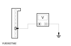
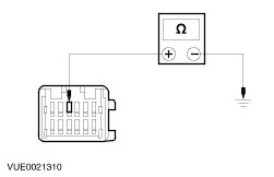
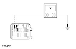
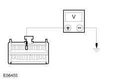
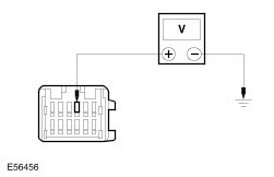
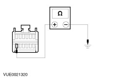
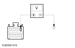
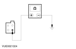
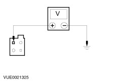
TEST the system for normal operation. | | A3: CHECK THE AUDIO UNIT CIRCUIT FOR POWER | | | 1 Disconnect Audio Unit C410. | | | 2 Measure the voltage between the audio unit C410 pin 1, (RD), harness side and ground. | | | Is the voltage greater than 10 volts? Yes No REPAIR the circuit. TEST the system for normal operation. | | A4: CHECK THE AUDIO UNIT CIRCUIT FOR POWER | | | 1 Ignition switch in position I. | | | 2 Measure the voltage between the audio unit C410 pin 3, (BN/RD), harness side and ground. | | | Is the voltage greater than 10 volts? Yes No REPAIR the circuit (BN/RD). TEST the system for normal operation. | | A5: CHECK THE AUDIO UNIT GROUND CIRCUIT(S) FOR OPEN | | | 1 Measure the resistance between the audio unit C410 pin 2, (BN), harness side and ground, and pin 6, (BN), harness side and ground. | | | Are the resistances less than 1 ohm? Yes INSTALL a new audio unit.
REFER to: Audio Unit (415-01 Audio Unit, Removal and Installation).
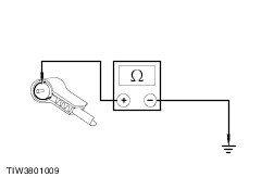
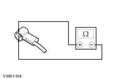
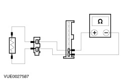
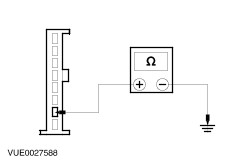
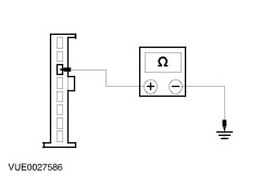
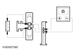
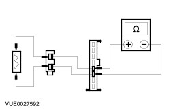
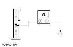
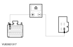
TEST the system for normal operation. No REPAIR the circuit(s). TEST the system for normal operation. | | PINPOINT TEST B : POOR RECEPTION | | TEST CONDITIONS | DETAILS/RESULTS/ACTIONS | | B1: CHECK ANTENNA GROUND | | | 1 Ignition switch in position 0. | | | 2 Disconnect Audio Unit Antenna Connector. | | | 3 Measure the resistance between the antenna screen and ground. | | | Is the resistance less than 1 ohm? Yes No CLEAN and TIGHTEN the audio unit case ground and the antenna mast base connection to the body. If concern persists, INSTALL a new antenna cable. TEST the system for normal operation. | | B2: CHECK ANTENNA CABLE FOR OPEN | | | 1 Remove the antenna mast. | | | 2 Measure the resistance between the center pin on the antenna connector and the antenna mast screw thread. | | | Is the resistance less than 1 ohm? Yes No INSTALL a new antenna cable. TEST the system for normal operation. | | B3: CHECK ANTENNA CABLE FOR SHORT | | | 1 Disconnect Antenna Base Connector. | | | 2 Measure the resistance between the center pin on the antenna core and the antenna screen. | | | Is the resistance greater than 10,000 ohms (open circuit)? Yes INSTALL a new antenna. TEST the system for normal operation. No INSTALL a new antenna cable. TEST the system for normal operation. | | PINPOINT TEST C : NO SOUND FROM ONE OR MORE OF THE SPEAKERS (LH SIDE FRONT) | | TEST CONDITIONS | DETAILS/RESULTS/ACTIONS | | C1: CHECK THE LH SIDE FRONT DOOR SPEAKER FOR CORRECT OPERATION | | | 1 Verify the operation of the LH side front door speaker. | | | Is the LH side front door speaker working correctly? Yes No | | C2: CHECK THE LH SIDE FRONT DOOR SPEAKER CIRCUIT FOR OPEN | | | 1 Disconnect Audio Unit C411. | | | 2 Disconnect LH Side Front Door Speaker C535. | | | 3 Disconnect LH Side Front Tweeter C166. | | | 4 Connect a fused jumper wire, between the LH side front door speaker C535 pin 1, (BU), and C535 pin 2, (BN/BU). | | | 5 Measure the resistance between the audio unit C411 pin 1, (BU), harness side and the audio unit C411 pin 2, (BN/BU), harness side. | | | Is the resistance less than 1 ohm? Yes No REPAIR the circuit(s). TEST the system for normal operation. | | C3: CHECK THE LH SIDE FRONT DOOR SPEAKER CIRCUIT FOR SHORT TO GROUND | | | 1 Measure the resistance between the audio unit C411 pin 2 (BN/BU), harness side ground. | | | Is the resistance greater than 10,000 ohms (open circuit)? Yes INSTALL a new LH side front door speaker. TEST the system for normal operation. If the concern persists, INSTALL a new audio unit.
REFER to: Audio Unit (415-01 Audio Unit, Removal and Installation).
TEST the system for normal operation. No REPAIR the short to ground. For additional information, REFER to the wiring diagrams. TEST the system for normal operation. | | C4: CHECK THE LH SIDE FRONT TWEETER CIRCUIT FOR OPEN. | | | 1 Disconnect Audio Unit C411. | | | 2 Disconnect LH Side Front Door Speaker C535. | | | 3 Disconnect LH Side Front Tweeter C166. | | | 4 Connect a fused jumper wire, between the LH side front tweeter C166 pin 1, (BU), and C166 pin 2, (BN/BU). | | | 5 Measure the resistance between the audio unit C411 pin 1, (BU), harness side and the audio unit C411 pin 2, (BN/BU), harness side. | | | Is the resistance less than 1 ohm? Yes No REPAIR the circuit(s). TEST the system for normal operation. | | C5: CHECK THE LH SIDE FRONT TWEETER CIRCUIT FOR SHORT TO GROUND | | | 1 Measure the resistance between the audio unit C411 pin 2 (BN/BU), harness side ground. | | | Is the resistance greater than 10,000 ohms (open circuit)? Yes INSTALL a new LH side front tweeter. TEST the system for normal operation. If the concern persists, INSTALL a new audio unit.
REFER to: Audio Unit (415-01 Audio Unit, Removal and Installation).
TEST the system for normal operation. No REPAIR the short to ground. For additional information, REFER to the wiring diagrams. TEST the system for normal operation. | | PINPOINT TEST D : NO SOUND FROM ONE OR MORE OF THE SPEAKERS (RH SIDE FRONT) | | TEST CONDITIONS | DETAILS/RESULTS/ACTIONS | | D1: CHECK THE RH SIDE FRONT DOOR SPEAKER FOR CORRECT OPERATION | | | 1 Verify the operation of the RH side front door speaker. | | | Is the RH side front door speaker working correctly? Yes No | | D2: CHECK THE RH SIDE FRONT DOOR SPEAKER CIRCUIT FOR OPEN | | | 1 Disconnect Audio Unit C411. | | | 2 Disconnect RH Side Front Door Speaker C536. | | | 3 Disconnect RH Side Front Tweeter C221. | | | 4 Connect a fused jumper wire, between the RH side front door speaker C536 pin 1, (RD), and C536 pin 2, (BN/RD). | | | 5 Measure the resistance between the audio unit C411 pin 5, (RD), harness side and pin 6, (BN/RD), harness side. | | | Is the resistance less than 1 ohm? Yes No REPAIR the circuit(s). TEST the system for normal operation. | | D3: CHECK THE RH SIDE FRONT DOOR SPEAKER CIRCUIT FOR SHORT TO GROUND | | | 1 Measure the resistance between the audio unit C411 pin 6, (BN/RD), harness side and ground. | | | Is the resistance greater than 10,000 ohms (open circuit)? Yes INSTALL a new RH side front door speaker. TEST the system for normal operation. If the concern persists, INSTALL a new audio unit.
REFER to: Audio Unit (415-01 Audio Unit, Removal and Installation).
TEST the system for normal operation. No REPAIR the short to ground. For additional information, REFER to the wiring diagrams. TEST the system for normal operation. | | D4: CHECK THE RH SIDE FRONT TWEETER CIRCUIT FOR OPEN | | | 1 Disconnect Audio Unit C411. | | | 2 Disconnect RH Side Front Door Speaker C536. | | | 3 Disconnect RH Side Front Tweeter C221. | | | 4 Connect a fused jumper wire, between the RH side front tweeter C221 pin 1, (BU), and C221 pin 2, (BN/BU). | | | 5 Measure the resistance between the audio unit C411 pin 5, (RD), harness side and pin 6, (BN/RD), harness side. | | | Is the resistance less than 1 ohm? Yes No REPAIR the circuit(s). TEST the system for normal operation. | | D5: CHECK THE RH SIDE FRONT DOOR TWEETER CIRCUIT FOR SHORT TO GROUND | | | 1 Measure the resistance between the audio unit C411 pin 6, (BN/RD), harness side and ground. | | | Is the resistance greater than 10,000 ohms (open circuit)? Yes INSTALL a new RH side front door tweeter. TEST the system for normal operation. If the concern persists, INSTALL a new audio unit.
REFER to: Audio Unit (415-01 Audio Unit, Removal and Installation).
TEST the system for normal operation. No REPAIR the short to ground. For additional information, REFER to the wiring diagrams. TEST the system for normal operation. | | PINPOINT TEST E : NO SOUND FROM ONE OR MORE OF THE SPEAKERS (LH SIDE REAR) | | TEST CONDITIONS | DETAILS/RESULTS/ACTIONS | | E1: CHECK THE LH SIDE REAR DOOR SPEAKERS FOR CORRECT OPERATION | | | 1 Verify the operation of the LH rear door speakers. | | | Are the LH rear door speakers working correctly? Yes (If vehicle is equipped with midline or highline audio unit), GO to E5. No | | E2: CHECK THE LH SIDE REAR DOOR SPEAKER FOR CORRECT OPERATION | | | 1 Verify the operation of the LH side rear door speaker. | | | Is the LH side rear door speaker working correctly? Yes No | | E3: CHECK THE LH SIDE REAR DOOR SPEAKER CIRCUIT FOR OPEN | | | 1 Disconnect Audio Unit C411. | | | 2 Disconnect LH Side Rear Door Speaker C537. | | | 3 Disconnect LH Side Third Seat Row Speaker C298 (if equipped). | | | 4 Connect a fused jumper wire, between the LH side rear door speaker C537 pin 1, (BU/WH), and C537 pin 2, (BN/WH). | | | 5 Measure the resistance between the audio unit C411 pin 3, (BU/WH), harness side and the audio unit C411 pin 4, harness side. | | | Is the resistance less than 1 ohm? Yes No REPAIR the circuit(s). TEST the system for normal operation. | | E4: CHECK THE LH SIDE REAR DOOR SPEAKER CIRCUIT FOR SHORT TO GROUND | | | 1 Measure the resistance between the audio unit C411 pin 4, (BN/WH), harness side and ground. | | | Is the resistance greater than 10,000 ohms (open circuit)? Yes INSTALL a new LH side rear door speaker. TEST the system for normal operation. If the concern persists, INSTALL a new audio unit.
REFER to: Audio Unit (415-01 Audio Unit, Removal and Installation).
TEST the system for normal operation. No REPAIR the short to ground. For additional information, REFER to the wiring diagrams. TEST the system for normal operation. | | E5: CHECK THE LH SIDE REAR THIRD SEAT ROW SPEAKER CIRCUIT FOR OPEN | | | 1 Disconnect Audio Unit C411. | | | 2 Disconnect LH Side Rear Door Speaker C537. | | | 3 Disconnect LH Side Rear Third Seat Row Speaker C298. | | | 4 Connect a fused jumper wire, between the LH side third row speaker C298 pin 1, (BU/WH), and C298 pin 2, (BN/WH). | | | 5 Measure the resistance between the audio unit C411 pin 3, (BU/WH), harness side and C411 pin 4, harness side. | | | Is the resistance less than 1 ohm? Yes No REPAIR the circuit(s). TEST the system for normal operation. | | E6: CHECK THE LH SIDE REAR THIRD SEAT ROW SPEAKER CIRCUIT FOR SHORT TO GROUND | | | 1 Measure the resistance between the audio unit C411 pin 4, (BN/WH), harness side and ground. | | | Is the resistance greater than 10,000 ohms (open circuit)? Yes INSTALL a new LH side rear third seat row speaker. TEST the system for normal operation. If the concern persists, INSTALL a new audio unit.
REFER to: Audio Unit (415-01 Audio Unit, Removal and Installation).
TEST the system for normal operation. No REPAIR the short to ground. For additional information, REFER to the wiring diagrams. TEST the system for normal operation. | | E7: CHECK THE LH REAR DOOR TWEETER CIRCUIT FOR OPEN | | | 1 Disconnect Audio Unit C411. | | | 2 Disconnect LH Side Rear Door Tweeter C537. | | | 3 Disconnect LH Side Rear Third Seat Row Speaker C298 (if equipped). | | | 4 Connect a fused jumper wire, between the LH side rear door tweeter C537 pin 1, (BN/ RD), and C537 pin 2, (RD). | | | 5 Measure the resistance between the audio unit C411 pin 3, (BU/WH) harness side, and the audio unit C411 pin 4, (BN/WH) harness side. | | | Is the resistances 4.5 ohms (rated speaker resistance ± 0.5 ohms)? Yes No REPAIR the circuit between the LH rear door speaker and the LH rear door tweeter. TEST the system for normal operation | | E8: CHECK THE LH SIDE REAR DOOR TWEETER CIRCUIT FOR SHORT TO GROUND | | | 1 Measure the resistance between the audio unit C411 pin 4, (BN/WH), harness side and ground. | | | | | | Is the resistance greater than 10,000 ohms (open circuit)? Yes INSTALL a new LH side rear tweeter. TEST the system for normal operation. If the concern persists, INSTALL a new audio unit.
REFER to: Audio Unit (415-01 Audio Unit, Removal and Installation).
TEST the system for normal operation. No REPAIR the short to ground. For additional information, REFER to the wiring diagrams. TEST the system for normal operation. | | PINPOINT TEST F : NO SOUND FROM ONE OR MORE OF THE SPEAKERS (RH SIDE REAR) | | TEST CONDITIONS | DETAILS/RESULTS/ACTIONS | | F1: CHECK THE RH SIDE REAR DOOR SPEAKER(S) FOR CORRECT OPERATION | | | 1 Verify the operation of the RH side rear door speaker(s). | | | Are the RH side rear speaker(s) working correctly? Yes (If vehicle is equipped with midline or highline audio unit), GO to F5. No | | F2: CHECK THE RH SIDE REAR DOOR SPEAKER FOR CORRECT OPERATION | | | 1 Verify the operation of the RH rear door speaker. | | | Is the RH rear door speaker working correctly? Yes No | | F3: CHECK THE RH SIDE REAR DOOR SPEAKER CIRCUIT FOR OPEN | | | 1 Disconnect Audio Unit C411. | | | 2 Disconnect RH Side Rear Door Speaker C538. | | | 3 Disconnect RH Side Rear Third Seat Row Speaker C297 (if equipped). | | | 4 Connect a fused jumper wire, between the RH side rear door speaker C538 pin 1, (RD/GN), and C538 pin 2, (BN/GY). | | | 5 Measure the resistance between the audio unit C411 pin 7, (RD/GN), harness side, and the audio unit C411 pin 8, (BN/GY), harness side. | | | Is the resistance less than 1 ohm? Yes No REPAIR the circuit(s). TEST the system for normal operation. | | F4: CHECK THE RH SIDE REAR DOOR SPEAKER CIRCUIT FOR SHORT TO GROUND | | | 1 Measure the resistance between the audio unit C411 pin 8 (BN/GY), harness side and ground. | | | Is the resistance greater than 10,000 ohms (open circuit)? Yes INSTALL a new RH side rear door speaker unit. TEST the system for normal operation. If the concern persists, INSTALL a new audio unit.
REFER to: Audio Unit (415-01 Audio Unit, Removal and Installation).
TEST the system for normal operation. No REPAIR the short to ground. For additional information, REFER to the wiring diagrams. TEST the system for normal operation. | | F5: CHECK THE RH SIDE REAR THIRD ROW SEAT SPEAKER CIRCUIT FOR OPEN | | | 1 Disconnect Audio Unit C411. | | | 2 Disconnect RH Side Rear Door Speaker C538. | | | 3 Disconnect RH Side Rear Third Seat Row Speaker C297. | | | 4 Connect a fused jumper wire, between the RH side rear third row seat tweeter C297 pin 1, (RD/GN), and C297 pin 2, (BN/GY). | | | 5 Measure the resistance between the audio unit C411 pin 7, (RD/GN) harness side, and C411 pin 8, (BN/GY) harness side. | | | Is the resistance less than 1 ohm? Yes No Repair the circuit(s). TEST the system for normal information. | | F6: CHECK THE RH SIDE REAR THIRD ROW SEAT SPEAKER CIRCUIT FOR SHORT TO GROUND | | | 1 Measure the resistance between the audio unit C411 pin 8, (BN/GY), harness side and ground. | | | Is the resistance greater than 10,000 ohms (open circuit)? Yes INSTALL a new RH side rear third row seat speaker. TEST the system for normal operation. If the concern persists, INSTALL a new audio unit.
REFER to: Audio Unit (415-01 Audio Unit, Removal and Installation).
No REPAIR the short to ground. For additional information, REFER to the wiring diagrams. TEST the system for normal operation. | | F7: CHECK THE LH REAR DOOR TWEETER CIRCUIT FOR OPEN | | | 1 Disconnect Audio Unit C411. | | | 2 Disconnect RH Side Rear Door Tweeter C538. | | | 3 Disconnect LH Side Rear Third Seat Row Speaker C297 (if equipped). | | | 4 Connect a fused jumper wire, between the RH side rear door tweeter C538 pin 1, (BN/ RD), and C538 pin 2, (RD). | | | 5 Measure the resistance between the audio unit C411 pin 7, (RD/GN) harness side, and the audio unit C411 pin 8, (BN/GY) harness side. | | | Is the resistances 4.5 ohms (rated speaker resistance ± 0.5 ohms)? Yes No REPAIR the circuit between the RH rear door speaker and the RH rear door tweeter. TEST the system for normal operation. | | F8: CHECK THE RH SIDE REAR DOOR TWEETER CIRCUIT FOR SHORT TO GROUND | | | 1 Measure the resistance between the audio unit C411 pin 8, (BN/GY), harness side and ground. | | | | | | Is the resistance greater than 10,000 ohms (open circuit)? Yes INSTALL a new RH side rear door tweeter. TEST the system for normal operation. If the concern persists, INSTALL a new audio unit.
REFER to: Audio Unit (415-01 Audio Unit, Removal and Installation).
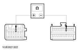
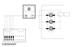
No REPAIR the short to ground. For additional information, REFER to the wiring diagrams. TEST the system for normal operation. | | PINPOINT TEST G : THE CD CHANGER IS INOPERATIVE/DOES NOT OPERATE CORRECTLY | | TEST CONDITIONS | DETAILS/RESULTS/ACTIONS | | G1: CHECK THE OPERATION OF THE CD CHANGER | | | 1 Turn on the audio unit. | | | 2 Verify the audio unit is operating correctly. Refer to the owner guide. | | | 3 Verify that the CD changer power loading function is operating correctly. Refer to the owner guide for CD loading instructions. | | | Is the CD changer information displayed on the audio unit display? Yes No | | G2: CHECK THE CD CHANGER CIRCUIT (RD/WH) FOR POWER | | | 1 Disconnect CD Changer C419. | | | 2 Measure the voltage between the CD changer C419 pin 9, (RD/WH), harness side and ground. | | | Is the voltage greater than 10 volts? Yes No INSTALL a new audio unit to CD changer wiring loom. TEST the system for normal operation. | | G3: CHECK THE CD CHANGER GROUND CIRCUIT FOR OPEN | | | 1 Measure the resistance between the CD changer C419 pin 3, (BN), harness side and ground. | | | Is the resistances less than 1 ohm? Yes INSTALL a new CD changer. TEST the system for normal operation. No INSTALL a new audio unit to CD changer wiring loom. TEST the system for normal operation. | | G4: CHECK THE CD CHANGER CIRCUITS FOR OPEN | | | 1 Disconnect Audio Unit C418. | | | 2 Disconnect CD Changer C419. | | | 3 Measure the resistance between each of the audio unit C418 pins, and the CD changer C419 pins: - Audio unit C418 pin 1, (YE), harness side and CD changer C419 pin 1, (YE), harness side.
- Audio unit C418 pin 7, (WH), harness side and CD changer C419 pin 7, (WH), harness side.
- Audio unit C418 pin 8, (YE/BK), harness side and CD changer C419 pin 8, (YE/BK), harness side.
- Audio unit C418 pin 5, (WH/BK), harness side and CD changer C419 pin 5, (WH/BK), harness side.
- Audio unit C418 pin 11, (GY/VT), harness side and CD changer C419 pin 11, (GY/VT), harness side.
- Audio unit C418 pin 6, (WH/GN), harness side and CD changer C419 pin 6, (WH/GN), harness side.
- Audio unit C418 pin 12, (GY/OG), harness side and CD changer C419 pin 12, (GY/OG), harness side.
- Audio unit C418 pin 10, (BK), harness side and CD changer C419 pin 10, (BK), harness side.
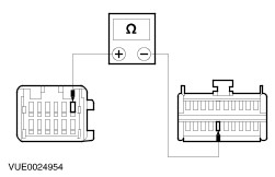
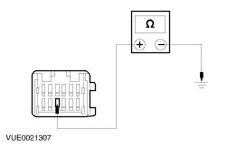
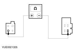
| | | | | | Are the resistances less than 1 ohm? Yes No INSTALL a new audio unit to CD changer wiring loom. TEST the system for normal operation. | | G5: CHECK THE CD CHANGER CIRCUITS FOR SHORT TO GROUND | | | 1 Measure the resistance between CD changer C419 pins, harness side and ground: - CD changer C419 pin 1, (YE), harness side and ground
- CD changer C419 pin 7, (WH), harness side and ground
- CD changer C419 pin 8, (YE/BK), harness side and ground
- CD changer C419 pin 5, (WH/BK), harness side and ground
- CD changer C419 pin 11, (GY/VT), harness side and ground
- CD changer C419 pin 6, (WH/GN), harness side and ground
- CD changer C419 pin 12, (GY/OG), harness side and ground
- CD changer C419 pin 10, (BK), harness side and ground
| | | | | | Are the resistance greater than 10,000 ohms (open circuit)? Yes INSTALL a new CD changer. TEST the system for normal operation. If concern persists, INSTALL a new audio unit.
REFER to: Audio Unit (415-01 Audio Unit, Removal and Installation).
TEST the system for normal operation. No INSTALL a new audio unit to CD changer wiring loom. TEST the system for normal operation. | | PINPOINT TEST H : THE VIDEO SYSTEM IS INOPERATIVE/DOES NOT OPERATE CORRECTLY | WARNING:Do not attempt to open or repair a video display as there are internal voltages in excess of 2000 volts. Failure to follow this instruction may result in personal injury. | | TEST CONDITIONS | DETAILS/RESULTS/ACTIONS | | H1: CHECK FRONT SEAT BACKREST UPPER VIDEO SYSTEM(S) OPERATION USING THE REMOTE CONTROL | | | 1 Operate the front seat backrest upper video system(s) with the remote control. | | | Do the front seat backrest upper video system(s) operated by the remote control turn white? Yes For concern with left-hand front seat backrest upper video system. GO to H2. For concern with right-hand front seat backrest upper video system. GO to H4. No If the front seat backrest upper video system(s) flickers. GO to H6. If the front seat backrest upper video system(s) are blank. GO to H14. | | H2: CHECK LEFT-HAND FRONT SEAT BACKREST UPPER VIDEO SYSTEM C644 (OG) FOR VOLTAGE | | | 1 Disconnect Left-Hand Front Seat Backrest Upper Video System C644. | | | 2 Measure the voltage between the left-hand front seat backrest upper video system C644 pin 6, (OG), harness side and ground. | | | Is the voltage greater than 10 volts? Yes No CHECK and REPAIR the circuit. TEST the system for normal operation. If the circuit is OK. INSTALL a new video system module.
REFER to: Video System Module - Vehicles Without: Digital Versatile Disc (DVD) Player/Digital Versatile Disc (DVD) Player (415-07 Video System, Removal and Installation) /
Video System Module - Vehicles With: Digital Versatile Disc (DVD) Player (415-07 Video System, Removal and Installation).
TEST the system for normal operation. If the concern persists, Install a new wiring harness between the video system module and the left-hand front seat backrest upper video system. TEST the system for normal operation. | | H3: CHECK LEFT-HAND FRONT SEAT BACKREST UPPER VIDEO SYSTEM C644 (NT) FOR GROUND | | | 1 Measure the resistance between the left-hand front seat backrest upper video system C644 pin 3, (NT), harness side and ground. | | | Is the resistance less than 0.5 ohms? Yes INSTALL a new head restraint/video display. TEST the system for normal operation. No REPAIR the circuit. TEST the system for normal operation. | | H4: CHECK RIGHT-HAND FRONT SEAT BACKREST UPPER VIDEO SYSTEM C642 (OG) FOR VOLTAGE | | | 1 Disconnect Right-Hand Front Seat Backrest Upper Video System C642. | | | 2 Measure the voltage between the right-hand front seat backrest upper video system C642 pin 6, (OG), harness side and ground. | | | Is the voltage greater than 10 volts? Yes No CHECK and REPAIR the circuit. TEST the system for normal operation. If the circuit is OK. INSTALL a new video system module.
REFER to: Video System Module - Vehicles Without: Digital Versatile Disc (DVD) Player/Digital Versatile Disc (DVD) Player (415-07 Video System, Removal and Installation) /
Video System Module - Vehicles With: Digital Versatile Disc (DVD) Player (415-07 Video System, Removal and Installation).
TEST the system for normal operation. If the concern persists, Install a new wiring harness between the video system module and the right-hand front seat backrest upper video system. TEST the system for normal operation. | | H5: CHECK RIGHT-HAND FRONT SEAT BACKREST UPPER VIDEO SYSTEM C642 (NT) FOR GROUND | | | 1 Measure the resistance between the right-hand front seat backrest upper video system C642 pin 3, (NT), harness side and ground. | | | Is the resistance less than 0.5 ohms? Yes INSTALL a new head restraint/video display. TEST the system for normal operation. No REPAIR the circuit. TEST the system for normal operation. | | H6: CHECK FRONT SEAT BACKREST UPPER VIDEO SYSTEM(S) FOR SCREEN FLICKER | | | 1 Operate the front seat backrest upper video system(s) with the remote control. | | | Do both front seat backrest upper video system screens operate then turn off? Yes No For concern with left-hand video display. INSTALL a new head restraint/video display. TEST the system for normal operation.For concern with right-hand video display. INSTALL a new head restraint/video display. TEST the system for normal operation. | | H7: CHECK FRONT SEAT BACKREST UPPER VIDEO SYSTEM(S) FOR OPERATION WITH THE OTHER DISCONNECTED | | | 1 Disconnect one of the front seat backrest upper video system electrical connector. | | | Does the other front seat backrest upper video system operate correctly? Yes INSTALL a new head restraint/video display. TEST the system for normal operation. No Subsititue the front seat backrest upper video system with the other front seat backrest upper video system and GO to Step 1. TEST the system for normal operation. If the concern persists, GO to H8. | | H8: CHECK FRONT SEAT BACKREST UPPER VIDEO SYSTEM(S) C644 AND C642 (BU) AND (GN) FOR VOLTAGE | | | 1 Disconnect Left-Hand Front Seat Backrest Upper Video System C644. | | | 2 Disconnect Right-Hand Front Seat Backrest Upper Video System C642. | | | CAUTION:Take care not to damage the front seat backrest upper video system electrical connector(s) when back probing the pin(s). 3 Measure the voltage by back probing between the front seat backrest upper video system(s) pin 1 and 2, harness side and ground as follows: | Connector | Circuit | | C644 (left-hand) | pin 1 (BU) and pin 2 (GN) | | C642 (right-hand) | pin 1 (BU) and pin 2 (GN) | | | | Are voltages greater than 4 volts? Yes For concern with left-hand front seat backrest upper video system. GO to H10. For concern with left-hand front seat backrest upper video system. GO to H11. No | | H9: CHECK FRONT SEAT BACKREST UPPER VIDEO SYSTEM(S) C644 AND C642 (BU) AND (GN) FOR VOLTAGE BETWEEN 2-3 VOLTS | | | CAUTION:Take care not to damage the front seat backrest upper video system electrical connector(s) when back probing the pin(s). 1 Measure the voltage by back probing between the front seat backrest upper video system(s) pin 1 and 2, harness side and ground as follows: | Connector | Circuit | | C644 (left-hand) | pin 1 (BU) and pin 2 (GN) | | C642 (right-hand) | pin 1 (BU) and pin 2 (GN) | | | | Are the voltages between 2-3 volts? Yes No Using a known good head restraint/video display, check the voltage again. If the voltage is correct, INSTALL a new head restraint/video display. TEST the system for normal operation. IF the voltage is 0 volts Install a new CJB. TEST the system for normal operation. | | H10: CHECK LEFT-HAND FRONT SEAT BACKREST UPPER VIDEO SYSTEM FOR BACKLIGHT VOLTAGE | | | CAUTION:Take care not to damage the front seat backrest upper video system electrical connector(s) when back probing the pin(s). 1 Measure the voltage by back probing between the left-hand front seat backrest upper video system C644 pin 1 (BU), harness side and pin 2 (GN), harness side. | | | Is the voltage greater than 10 volts? Yes INSTALL a new head restraint/video display. TEST the system for normal operation. No CHECK and REPAIR the circuit(s). TEST the system for normal operation. If the circuit is OK. INSTALL a new video system module.
REFER to: Video System Module - Vehicles Without: Digital Versatile Disc (DVD) Player/Digital Versatile Disc (DVD) Player (415-07 Video System, Removal and Installation) /
Video System Module - Vehicles With: Digital Versatile Disc (DVD) Player (415-07 Video System, Removal and Installation).
TEST the system for normal operation. If the concern persists, Install a new wiring harness between the video system module and the left-hand front seat backrest upper video system. TEST the system for normal operation. | | H11: CHECK RIGHT-HAND FRONT SEAT BACKREST UPPER VIDEO SYSTEM FOR BACKLIGHT VOLTAGE | | | CAUTION:Take care not to damage the front seat backrest upper video system electrical connector(s) when back probing the pin(s). 1 Measure the voltage by back probing between the right-hand front seat backrest upper video system C642 pin 1 (BU), harness side and pin 2 (GN), harness side. | | | Is the voltage greater than 10 volts? Yes INSTALL a new head restraint/video display. TEST the system for normal operation. No CHECK and REPAIR the circuit(s). TEST the system for normal operation. If the circuit is OK. INSTALL a new video system module.
REFER to: Video System Module - Vehicles Without: Digital Versatile Disc (DVD) Player/Digital Versatile Disc (DVD) Player (415-07 Video System, Removal and Installation) /
Video System Module - Vehicles With: Digital Versatile Disc (DVD) Player (415-07 Video System, Removal and Installation).
TEST the system for normal operation. If the concern persists, Install a new wiring harness between the video system module and the right-hand front seat backrest upper video system. TEST the system for normal operation. | | H12: CHECK PASSENGER ENTERTAINMENT CONTROL PANEL C648 (WH) FOR VOLTAGE | | | 1 Connect Left-Hand Front Seat Backrest Upper Video System C644. | | | 2 Connect Right-Hand Front Seat Backrest Upper Video System C642. | | | 3 Disconnect Passenger Entertainment Control Panel C648. | | | NOTE:The video system will still operate using the remote control. 4 Measure the voltage between the passenger entertainment control panel C648 pin 3 (WH), harness side and ground | | | Is the voltage between 4-5 volts? Yes INSTALL a new CJB. TEST the system for normal operation. No If the voltage is less than 4 volts, GO to H13. | | H13: CHECK PASSENGER ENTERTAINMENT CONTROL PANEL C648 (YE) FOR VOLTAGE | | | 1 Measure the voltage between the passenger entertainment control panel C648 pin 6 (YE), harness side and ground | | | Is the voltage greater than 10 volts? Yes INSTALL a new passenger entertainment control panel. TEST the system for normal operation. No INSTALL a new CJB. TEST the system for normal operation. | | H14: CHECK VOLTAGE AT FRONT SEAT BACKREST UPPER VIDEO SYSTEM(S) C644 AND C642 PIN 4 (WH) | | | CAUTION:Take care not to damage the front seat backrest upper video system electrical connector(s) when back probing the pin(s). 1 Measure the voltage by back probing between the front seat backrest upper video system pin 4 (WH), harness side and ground as follows: | Connector | Circuit | | C644 (left-hand) | pin 4 (WH) | | C642 (right-hand) | pin 4 (WH) | | | | Are the voltages between 4-5 volts? Yes No If the voltage is 0-1 volt, GO to H15. If the voltage is 1-4 volts, INSTALL head restraint/video display(s) as necessary. TEST the system for normal operation.If the voltage is greater than 5 volts. CHECK ground connections. TEST the system for normal operation. | | H15: CHECK FRONT SEAT BACKREST UPPER VIDEO SYSTEM(S) C644 AND C642 PIN 4 (WH) FOR VOLTAGE DROP | | | CAUTION:Take care not to damage the front seat backrest upper video system electrical connector(s) when back probing the pin(s). 1 Measure the voltage by back probing between the front seat backrest upper video system pin 4 (WH), harness side and ground while disconnecting the other front seat backrest upper video system as follows: | Connector | Circuit | | C644 (left-hand) | pin 4 (WH) | | C642 (right-hand) | pin 4 (WH) | | | | Is the voltage between 0-1 volt with other head restraint/video display disconnected? Yes INSTALL a new CJB. TEST the system for normal operation. No INSTALL front seat backrest upper video system(s) as necessary. TEST the system for normal operation. | | H16: CHECK VIDEO SYSTEM MODULE C622 (RD) FOR VOLTAGE | | | 1 Disconnect Video System Module C622. | | | 2 Measure the voltage between the video system module C622 pin 6, (RD), harness side and ground. | | | Is the voltage greater than 10 volts? Yes No | | H17: CHECK THE VIDEO SYSTEM MODULE C622 (BK) FOR GROUND | | | 1 Measure the resistance between the video system module C622 pin 12, (BK), harness side and ground. | | | Is the resistance less than 0.5 ohms? Yes No REPAIR the ground circuit (BK). TEST the system for normal operation. | | H18: CHECK SWITCHED POWER TO VIDEO SYSTEM MODULE C622 (WH/RD) WITH AUDIO UNIT SWITCHED ON | | | 1 Switch the audio unit ON. | | | 2 Measure the voltage between the video system module C622 pin 1, (WH/RD), harness side and ground. | | | Is the voltage greater than 10 volts? Yes INSTALL a new video system module.
REFER to: Video System Module - Vehicles Without: Digital Versatile Disc (DVD) Player/Digital Versatile Disc (DVD) Player (415-07 Video System, Removal and Installation) /
Video System Module - Vehicles With: Digital Versatile Disc (DVD) Player (415-07 Video System, Removal and Installation).
TEST the system for normal operation. No REPAIR the circuit (WH/RD). TEST the system for normal operation. | | H19: CHECK POWER CIRCUIT BETWEEN VIDEO SYSTEM MODULE C622 (RD) AND AUDIO UNIT C524 (RD) FOR OPEN | | | 1 Disconnect Audio Unit C524. | | | 2 Measure the resistance between the video system module C622 pin 6, (RD), harness side and the audio unit C524 pin 1, (RD), harness side. | | | Is the resistance less than 1 ohm? Yes No REPAIR the circuit (RD). TEST the system for normal operation. | | H20: CHECK SWITCHED POWER CIRCUIT BETWEEN VIDEO SYSTEM MODULE C622 (WH/RD) AND AUDIO UNIT C524 (WH/RD) FOR OPEN | | | 1 Measure the resistance between the video system module C622 pin 1, (WH/RD), harness side and the audio unit C524 pin 2, (WH/RD), harness side. | | | Is the resistance less than 1 ohm? Yes INSTALL a new audio unit.
REFER to: Audio Unit (415-01 Audio Unit, Removal and Installation).
TEST the system for normal operation. No REPAIR the circuit (WH/RD). TEST the system for normal operation. | | PINPOINT TEST I : NO AUXILIARY HEADPHONE AUDIO | | TEST CONDITIONS | DETAILS/RESULTS/ACTIONS | | I1: CHECK THE HEADPHONE AND HEADPHONE SOCKETS | | | 1 Using a known good headphone, check the headphone in the right-hand and left-hand sockets. | | | Does the substitute headphone operate correctly? Yes INSTALL a new headphone. TEST the system for normal operation. No No output from either channel, GO to I2. No output from the right-hand channel, GO to I4. No output from the left-hand channel, GO to I5. | | I2: CHECK THE VIDEO SYSTEM MEDIA FOR AUDIO INPUT | | | 1 Connect the video cassette player or DVD player direct to the passenger entertainment control panel and operate the media device. | | | Does the passenger entertainment control panel input media sound? Yes INSTALL a new video cassette player.
REFER to: Video Cassette Player (415-07 Video System, Removal and Installation).
or INSTALL a new DVD player.
REFER to: Digital Versatile Disc (DVD) Player (415-07 Video System, Removal and Installation).
as necessary. TEST the system for normal operation. No | | I3: CHECK THE PASSENGER ENTERTAINMENT CONTROL PANEL C648 (GN) FOR GROUND | | | 1 Measure the resistance between the passenger entertainment control panel C648 pin 16, (GN), harness side and ground. | | | Is the resistance less than 0.5 ohms? Yes INSTALL a new video system module.
REFER to: Video System Module - Vehicles Without: Digital Versatile Disc (DVD) Player/Digital Versatile Disc (DVD) Player (415-07 Video System, Removal and Installation) /
Video System Module - Vehicles With: Digital Versatile Disc (DVD) Player (415-07 Video System, Removal and Installation).
TEST the system for normal operation. No REPAIR the circuit (GN). TEST the system for normal operation. | | I4: CHECK RIGHT-HAND HEADPHONES CHANNEL (RD) AND (RD/BU) FOR OPEN | | | 1 Disconnect Video System Module C647. | | | 2 Disconnect Passenger Entertainment Control Panel C648. | | | 3 Measure the resistances between the video system module C647 pin 1, (RD), harness side and the passenger entertainment control panel C648 pin 2, (RD), harness side and between the video system module C647 pin 4, (RD/BU), harness side and the passenger entertainment control panel C648 pin 5, (RD/BU), harness side. | | | Are the resistances less than 1 ohm? Yes No REPAIR the circuit(s) as necessary. TEST the system for normal operation. | | I5: CHECK LEFT-HAND HEADPHONES CHANNEL (BU) AND (GY/RD) FOR OPEN | | | 1 Disconnect Video System Module C647. | | | 2 Disconnect Passenger Entertainment Control Panel C648. | | | 3 Measure the resistances between the video system module C647 pin 2, (BU), harness side and the passenger entertainment control panel C648 pin 1, (BU), harness side and between the video system module C647 pin 5, (GY/RD), harness side and the passenger entertainment control panel C648 pin 4, (GY/RD), harness side. | | | Are the resistances less than 1 ohm? Yes No REPAIR the circuit(s) as necessary. TEST the system for normal operation. | | I6: CHECK THE PASSENGER ENTERTAINMENT CONTROL PANEL FOR CONTINUITY | | | 1 Measure the resistance between the passenger entertainment control panel C648, component side and the headphone sockets: - pins 4 and 5 and the left-hand headphone sockets
- pins 1 and 2 and the right-hand headphone sockets
| | | Are the resistances less than 0.5 ohms? Yes INSTALL a new video system module.
REFER to: Video System Module - Vehicles Without: Digital Versatile Disc (DVD) Player/Digital Versatile Disc (DVD) Player (415-07 Video System, Removal and Installation) /
Video System Module - Vehicles With: Digital Versatile Disc (DVD) Player (415-07 Video System, Removal and Installation).
TEST the system for normal operation. No INSTALL a new passenger entertainment control panel. TEST the system for normal operation. | | PINPOINT TEST J : THE VIDEO DISPLAY IS INOPERATIVE/DOES NOT OPERATE CORRECTLY | WARNING:Do not attempt to open or repair a video display as there are internal voltages in excess of 2000 volts. Failure to follow this instruction may result in personal injury. | | TEST CONDITIONS | DETAILS/RESULTS/ACTIONS | | J1: CHECK OPERATION OF THE VIDEO DISPLAY | | | 1 Change the head restraints/video displays between the two front seats. | | | Has the concern moved with the video display? Yes INSTALL a new head restraint/video display. TEST the system for normal operation. No For concern with right-hand video display GO to J2. For concern with left-hand video display GO to J8. | | J2: CHECK RIGHT-HAND FRONT SEAT BACKREST UPPER VIDEO SYSTEM C642 (OG) FOR VOLTAGE | | | 1 Disconnect Right-Hand Front Seat Backrest Upper Video System C642. | | | 2 Measure the voltage between the right-hand front seat backrest upper video system C642 pin 6, (OG), harness side and ground. | | | Is the voltage greater than 10 volts? Yes No | | J3: CHECK RIGHT-HAND FRONT SEAT BACKREST UPPER VIDEO SYSTEM C642 (NT) FOR GROUND | | | 1 Measure the resistance between the right-hand front seat backrest upper video system C642 pin 3, (NT), harness side and ground. | | | Is the resistance less than 0.5 ohms? Yes No REPAIR the circuit (NT). TEST the system for normal operation. | | J4: CHECK POWER CIRCUIT BETWEEN RIGHT-HAND FRONT SEAT BACKREST UPPER VIDEO C642 (OG) AND VIDEO SYSTEM MODULE C517 (OG) FOR OPEN | | | 1 Disconnect Video System Module C517. | | | 2 Measure the resistance between the right-hand front seat backrest upper video system C642 pin 6, (OG), harness side and the video system module C517 pin 16, (OG), harness side. | | | Is the resistance less than 1 ohm? Yes No REPAIR the circuit (OG). TEST the system for normal operation. | | J5: CHECK RIGHT-HAND FRONT SEAT BACKREST UPPER VIDEO SYSTEM C642 (RD) FOR ILLUMINATION VOLTAGE | | | 1 Measure the voltage between the right-hand front seat backrest upper video system C642 pin 12, (RD), harness side and ground. | | | Is the voltage greater than 10 volts? Yes No | | J6: CHECK RIGHT-HAND FRONT SEAT BACKREST UPPER VIDEO SYSTEM C642 (BK) FOR ILLUMINATION GROUND | | | 1 Measure the resistance between the right-hand front seat backrest upper video system C642 pin 9, (BK), harness side and ground. | | | Is the resistance less than 0.5 ohms? Yes No REPAIR the circuit (BK). TEST the system for normal operation. | | J7: CHECK CIRCUIT BETWEEN RIGHT-HAND FRONT SEAT BACKREST UPPER VIDEO SYSTEM C642 (RD) AND VIDEO SYSTEM MODULE C517 (RD) FOR OPEN | | | 1 Disconnect Video System Module C517. | | | 2 Measure the resistance between the right-hand front seat backrest upper video system C642 pin 12, (RD), harness side and the video system module C517 pin 20, (RD), harness side. | | | Is the resistance less than 1 ohm? Yes INSTALL a new video system module.
REFER to: Video System Module - Vehicles Without: Digital Versatile Disc (DVD) Player/Digital Versatile Disc (DVD) Player (415-07 Video System, Removal and Installation) /
Video System Module - Vehicles With: Digital Versatile Disc (DVD) Player (415-07 Video System, Removal and Installation).
TEST the system for normal operation. No REPAIR the circuit(s) (RD). TEST the system for normal operation. | | J8: CHECK LEFT-HAND FRONT SEAT BACKREST UPPER VIDEO SYSTEM C644 (OG) FOR VOLTAGE | | | 1 Disconnect Left-Hand Front Seat Backrest Upper Video System C644. | | | 2 Measure the voltage between the left-hand front seat backrest upper video system C644 pin 6, (OG), harness side and ground. | | | Is the voltage greater than 10 volts? Yes No | | J9: CHECK LEFT-HAND FRONT SEAT BACKREST UPPER VIDEO SYSTEM C644 (NT) FOR GROUND | | | 1 Measure the resistance between the left-hand front seat backrest upper video system C644 pin 3, (NT), harness side and ground. | | | Is the resistance less than 0.5 ohms? Yes No REPAIR the circuit. TEST the system for normal operation. | | J10: CHECK POWER CIRCUIT BETWEEN LEFT-HAND FRONT SEAT BACKREST UPPER VIDEO C644 (OG) AND VIDEO SYSTEM MODULE C517 (OG) FOR OPEN | | | 1 Disconnect Video System Module C517. | | | 2 Measure the resistance between the left-hand front seat backrest upper video system C644 pin 6, (OG), harness side and the video system module C517 pin 6, (OG), harness side. | | | Is the resistance less than 1 ohm? Yes No REPAIR the circuit(s). TEST the system for normal operation. | | J11: CHECK LEFT-HAND FRONT SEAT BACKREST UPPER VIDEO SYSTEM C644 (RD) FOR ILLUMINATION VOLTAGE | | | 1 Measure the voltage between the left-hand front seat backrest upper video system C644 pin 12, (RD), harness side and ground. | | | Is the voltage greater than 10 volts? Yes No | | J12: CHECK LEFT-HAND FRONT SEAT BACKREST UPPER VIDEO SYSTEM C644 CIRCUIT (BK) FOR ILLUMINATION GROUND | | | 1 Measure the resistance between the left-hand front seat backrest upper video system C644 pin 9, (BK), harness side and ground. | | | Is the resistance less than 0.5 ohms? Yes No REPAIR the circuit. TEST the system for normal operation. | | J13: CHECK CIRCUIT BETWEEN LEFT-HAND FRONT SEAT BACKREST UPPER VIDEO SYSTEM C644 (RD) AND VIDEO SYSTEM MODULE C517 (RD) FOR OPEN | | | 1 Disconnect Video System Module C517. | | | 2 Measure the resistance between the left-hand front seat backrest upper video system C644 pin 12, (RD), harness side and the video system module C517 pin 10, (RD), harness side. | | | Is the resistance less than 1 ohm? Yes INSTALL a new video system module.
REFER to: Video System Module - Vehicles Without: Digital Versatile Disc (DVD) Player/Digital Versatile Disc (DVD) Player (415-07 Video System, Removal and Installation) /
Video System Module - Vehicles With: Digital Versatile Disc (DVD) Player (415-07 Video System, Removal and Installation).
TEST the system for normal operation. No REPAIR the circuit(s) (RD). TEST the system for normal operation. | | PINPOINT TEST K : THE VIDEO CASSETTE PLAYER IS INOPERATIVE/DOES NOT OPERATE CORRECTLY | | TEST CONDITIONS | DETAILS/RESULTS/ACTIONS | | K1: CHECK VIDEO CASSETTE PLAYER C519 (RD) FOR VOLTAGE | | | 1 Disconnect Video Cassette Player C519. | | | 2 Measure the voltage between the video cassette player C519 pin 1, (RD), harness side and ground. | | | Is the voltage greater than 10 volts? Yes No | | K2: CHECK VIDEO CASSETTE PLAYER C519 (BK) FOR GROUND | | | 1 Measure the resistance between the video cassette player C519 pin 2, (BK), harness side and ground. | | | Is the resistance less than 0.5 ohms? Yes No REPAIR the circuit (BK). TEST the system for normal operation. | | K3: CHECK SWITCHED POWER CIRCUIT TO THE VIDEO CASSETTE PLAYER C519 (OG) WITH THE AUDIO UNIT SWITCHED ON | | | 1 Switch the audio unit ON. | | | 2 Measure the voltage between the video cassette player C519 pin 3, (OG), harness side and ground. | | | Is the voltage greater than 10 volts? Yes INSTALL a new video cassette player.
REFER to: Video Cassette Player (415-07 Video System, Removal and Installation).
TEST the system for normal operation. No | | K4: CHECK POWER CIRCUIT BETWEEN AUDIO UNIT C524 (RD) AND VIDEO CASSETTE PLAYER C519 (RD) FOR OPEN | | | 1 Disconnect Audio Unit C524. | | | 2 Measure the resistance between the audio unit C524 pin 1, (RD), harness side and the video cassette player C519 pin 1, (RD), harness side. | | | Is the resistance less than 1 ohm? Yes No REPAIR the circuit (RD). TEST the system for normal operation. | | K5: CHECK SWITCHED POWER CIRCUIT BETWEEN THE AUDIO UNIT C524 (RD/WH) AND THE VIDEO CASSETTE PLAYER C519 (OG) FOR OPEN | | | 1 Measure the resistance between the audio unit C524 pin 2, (RD/WH), harness side and the video cassette player C519 pin 3, (OG), harness side. | | | Is the resistance less than 1 ohm? Yes INSTALL a new audio unit.
REFER to: Audio Unit (415-01 Audio Unit, Removal and Installation).
TEST the system for normal operation. No REPAIR the circuit (OG). TEST the system for normal operation. | | PINPOINT TEST L : REMOTE CONTROL IS INOPERATIVE/DOES NOT OPERATE CORRECTLY | | TEST CONDITIONS | DETAILS/RESULTS/ACTIONS | | L1: CHECK OPERATION OF THE INFRARED SENSORS USING THE REMOTE CONTROL | NOTE:Refer to the Multimedia System Operating Guide for full operating instructions. | | | 1 Operate the remote control while pointing it at the infrared sensor of each video display in turn. | | | 2 Change the head restraints/video displays between the two front seats. | | | Has the concern moved with the video display? Yes INSTALL a new head restraint/video display. TEST the system for normal operation. No For concern with left-hand video display GO to L2. For concern with right-hand video display GO to L3. | | L2: CHECK CIRCUIT BETWEEN LEFT-HAND FRONT SEAT BACKREST UPPER VIDEO SYSTEM C661 (WH) AND VIDEO SYSTEM MODULE C517 (WH) FOR OPEN | | | 1 Disconnect Left-Hand Front Seat Backrest Upper Video System C661. | | | 2 Disconnect Video System Module C517. | | | 3 Measure the resistance between the left-hand front seat backrest upper video system C661 pin 4, (WH), harness side and the video system module C517 pin 4, (WH), harness side. | | | Is the resistance less than 1 ohm? Yes No REPAIR the circuit (WH). TEST the system for normal operation. | | L3: CHECK CIRCUIT BETWEEN RIGHT-HAND FRONT SEAT BACKREST UPPER VIDEO SYSTEM C528 (WH) AND VIDEO SYSTEM MODULE C517 (WH) FOR OPEN | | | 1 Disconnect Right-Hand Front Seat Backrest Upper Video System C662. | | | 2 Disconnect Video System Module C517. | | | 3 Measure the resistance between the left-hand front seat backrest upper video system C662 pin 4, (WH), harness side and the video system module C517 pin 14, (WH), harness side. | | | Is the resistance less than 1 ohm? Yes No REPAIR the circuit (WH). TEST the system for normal operation. | | L4: CHECK THE VIDEO CASSETTE PLAYER OPERATION USING THE CONTROLS ON THE VIDEO CASSETTE PLAYER | | | 1 Operate the video cassette player using the controls on the video cassette player. | | | Does the video cassette player operate correctly? Yes INSTALL a new remote control. TEST the system for normal operation. No | | L5: CHECK OPERATION OF THE VIDEO SYSTEM USING THE PASSENGER ENTERTAINMENT CONTROL PANEL | | | 1 Operate the video system using the controls on the passenger entertainment control panel. | | | Does the video system operate correctly? Yes INSTALL a new remote control. TEST the system for normal operation. No INSTALL a new video system module.
REFER to: Video System Module - Vehicles Without: Digital Versatile Disc (DVD) Player/Digital Versatile Disc (DVD) Player (415-07 Video System, Removal and Installation) /
Video System Module - Vehicles With: Digital Versatile Disc (DVD) Player (415-07 Video System, Removal and Installation).
TEST the system for normal operation. | | PINPOINT TEST M : EXTERNAL GAME CONSOLE/MEDIA SOURCE IS INOPERATIVE/DOES NOT OPERATE CORRECTLY | WARNING:An inverter is required (not supplied by Ford) to convert the vehicle battery voltage to mains voltage to power external games consoles etc. Make sure the inverter cable has not become broken, split or damaged. Failure to follow this instruction may result in personal injury. | NOTE:Make sure that the external game console/media source device operates correctly out of the vehicle before commencing diagnostics. | | TEST CONDITIONS | DETAILS/RESULTS/ACTIONS | | M1: CHECK POWER OUTLET C525 (RD) FOR VOLTAGE | | | 1 Disconnect Power Outlet C525. | | | 2 Measure the voltage between the power outlet C525 pin 1, (RD), harness side and ground. | | | Is the voltage greater than 10 volts? Yes No REPAIR the circuit (RD). TEST the system for normal operation. | | M2: CHECK POWER OUTLET C525 (BK) FOR GROUND | | | 1 Measure the resistance between the power outlet C525 pin 3, (BK), harness side and ground. | | | Is the resistance less than 0.5 ohms? Yes No REPAIR the circuit (BK). TEST the system for normal operation. | | M3: CHECK PASSENGER ENTERTAINMENT CONTROL PANEL C648 (GN) FOR GROUND | | | 1 Measure the resistance between the passenger entertainment control panel C648 pin 16, (GN), harness side and ground. | | | Is the resistance less than 0.5 ohms? Yes No REPAIR the circuit (GN). TEST the system for normal operation. | | M4: CHECK PASSENGER ENTERTAINMENT CONTROL PANEL C648 (BK) FOR VIDEO GROUND | | | 1 Measure the resistance between the passenger entertainment control panel C648 pin 12, (BK), harness side and ground. | | | Is the resistance less than 0.5 ohms? Yes No REPAIR the circuit (BK). TEST the system for normal operation. | | M5: CHECK VIDEO CIRCUIT BETWEEN PASSENGER ENTERTAINMENT CONTROL PANEL C648 (VT) AND VIDEO SYSTEM MODULE C647 (VT) | | | 1 Disconnect Video System Module C647. | | | 2 Measure the resistance between the passenger entertainment control panel C648 pin 11, (VT), harness side and the video system module C647 pin 7, (VT), harness side. | | | Is the resistance less than 1 ohm? Yes No REPAIR the circuit (VT). TEST the system for normal operation. | | M6: CHECK RIGHT-HAND AUDIO CIRCUIT BETWEEN PASSENGER ENTERTAINMENT CONTROL PANEL C648 (PK) AND VIDEO SYSTEM MODULE C647 (PK) | | | 1 Measure the resistance between the passenger entertainment control panel C648 pin 13, (PK), harness side and the video system module C647 pin 9, (PK), harness side. | | | Is the resistance less than 1 ohm? Yes No REPAIR the circuit (PK). TEST the system for normal operation. | | M7: CHECK LEFT-HAND AUDIO CIRCUIT BETWEEN PASSENGER ENTERTAINMENT CONTROL PANEL C648 (GY) AND VIDEO SYSTEM MODULE C647 (GY) | | | 1 Measure the resistance between the passenger entertainment control panel C648 pin 14, (GY), harness side and the video system module C647 pin 10, (GY), harness side. | | | Is the resistance less than 1 ohm? Yes No REPAIR the circuit (GY). TEST the system for normal operation. | | M8: CHECK THE PASSENGER ENTERTAINMENT CONTROL PANEL FOR CONTINUITY | | | 1 Measure the resistances between the passenger entertainment control panel C648, component side and the auxiliary input sockets: - pin 11 and the yellow video input socket center pin
- pin 12 and the yellow video input socket outer shield
- pin 13 and the red audio input socket center pin
- pin 14 and the white audio input socket center pin
- pin 15 and the red audio input socket outer shield
- pin 15 and the white audio input socket outer shield
| | | Are the resistances less than 0.5 ohms? Yes INSTALL a new video system module.
REFER to: Video System Module - Vehicles Without: Digital Versatile Disc (DVD) Player/Digital Versatile Disc (DVD) Player (415-07 Video System, Removal and Installation) /
Video System Module - Vehicles With: Digital Versatile Disc (DVD) Player (415-07 Video System, Removal and Installation).
TEST the system for normal operation. No INSTALL a new passenger entertainment control panel. TEST the system for normal operation. | | PINPOINT TEST N : THE DIGITAL VERSATILE DISC (DVD) PLAYER IS INOPERATIVE/DOES NOT OPERATE CORRECTLY | | TEST CONDITIONS | DETAILS/RESULTS/ACTIONS | | N1: CHECK DVD PLAYER C646 (RD) FOR VOLTAGE | | | 1 Disconnect DVD Player C646. | | | 2 Measure the voltage between the DVD player C646 pin 4, (RD), harness side and ground. | | | Is the voltage greater than 10 volts? Yes No | | N2: CHECK DVD PLAYER C646 (BK) FOR GROUND | | | 1 Measure the resistance between the DVD player C646 pin 8, (BK), harness side and ground. | | | Is the resistance less than 0.5 ohms? Yes No REPAIR the circuit (BK). TEST the system for normal operation. | | N3: CHECK SWITCHED POWER CIRCUIT TO THE DVD PLAYER C646 (PK) WITH THE AUDIO UNIT AND VIDEO SYSTEM SWITCHED ON | | | 1 Switch the audio unit and video system ON. | | | 2 Measure the voltage between the DVD player C646 pin 7, (PK), harness side and ground. | | | Is the voltage greater than 10 volts? Yes INSTALL a new DVD player.
REFER to: Digital Versatile Disc (DVD) Player (415-07 Video System, Removal and Installation).
TEST the system for normal operation. No | | N4: CHECK POWER CIRCUIT BETWEEN VIDEO SYSTEM MODULE C649 (RD) AND DVD PLAYER C646 (RD) FOR OPEN | | | 1 Disconnect Video system module C649. | | | 2 Measure the resistance between the video system module C649 pin 6, (RD), harness side and the DVD player C646 pin 4, (RD), harness side. | | | Is the resistance less than 5 ohms? Yes No REPAIR the circuit (RD). TEST the system for normal operation. | | N5: CHECK SWITCHED POWER CIRCUIT BETWEEN THE VIDEO SYSTEM MODULE C649 (PK) AND THE DVD PLAYER C646 (PK) FOR OPEN | | | 1 Measure the resistance between the video system module C649 pin 3, (PK), harness side and the DVD player C646 pin 7, (PK), harness side. | | | Is the resistance less than 0.5 ohms? Yes INSTALL a new video system module.
REFER to: Video System Module - Vehicles With: Digital Versatile Disc (DVD) Player (415-07 Video System, Removal and Installation).
TEST the system for normal operation. No REPAIR the circuit (PK). TEST the system for normal operation. | |