| Diagnosis and Testing Refer to Wiring Diagrams Section 417-01, for schematic and connector information. Special Tool(s) | | Terminal probe kit 29-011A | Inspection and Verification NOTE:The generic electronic module (GEM) is part of the central junction box (CJB). NOTE:If a new GEM module is being installed, the new module must be configured following installation. For this purpose, the vehicle-specific data is read out of the module to be changed using WDS and is transferred to the new module.REFER to: Module Configuration (418-01 Module Configuration, General Procedures), Generic Electronic Module (GEM) (419-10 Multifunction Electronic Modules, Diagnosis and Testing). NOTE:Before reading out the vehicle-specific data make sure that all electrical connections in the vehicle are reconnected so that the module and WDS can communicate correctly. - Verify the customer concern.
- Visually inspect for obvious signs of electrical damage.
Visual Inspection Chart | Electrical | - Fuse(s)
- Bulb(s)
- Electrical connector(s)
- Switch(es)
- Wiring harness
| - If an obvious cause for an observed or reported concern is found, correct the cause (if possible) before proceeding to the next step.
- If the concern is not visually evident, verify the symptom and refer to the Symptom Chart.
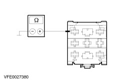
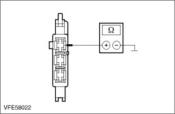
Symptom Chart Symptom Chart | Symptom | Possible Sources | Action | | The reversing lamps are inoperative | * Fuse(s) * Circuit(s) * Transmission control switch * Automatic transmission relay * Central Junction Box (CJB) | * | | One reversing lamp is inoperative | * Circuit(s) * Tailgate lamp assembly | * | | The reversing lamps are on continuously | * Circuit(s) * Transmission control switch * Parking aid module * Auto-dimming interior mirror * Audio/navigation control unit * Automatic transmission relay * Trailer socket | * | Pinpoint Tests NOTE:Use a digital multimeter for all electrical measurements. | PINPOINT TEST A : THE REVERSING LAMPS ARE INOPERATIVE | | TEST CONDITIONS | DETAILS/RESULTS/ACTIONS | | A1: CHECK FUSE F5 (15 A) (CJB) | | | 1 Ignition switch in position 0. | | | 2 Disconnect fuse F5 (15 A) (CJB). | | | 3 CHECK fuse F5 (15 A) (CJB). | | | Is the fuse OK? Yes No INSTALL a new fuse F5 (15 A) and TEST the system for normal operation. If the fuse blows again, LOCATE and REPAIR the short circuit by using the wiring diagrams. TEST the system for normal operation. | | A2: CHECK THE VOLTAGE AT FUSE F5 (15 A) (CJB) | | | 1 Connect fuse F5 (15 A) (CJB). | | | 2 Ignition switch in position II. | | | 3 Measure the voltage between fuse F5 (15 A) (CJB) and ground. | | | Is battery voltage indicated? Yes - Vehicles with manual transmission: GO to A3. - Vehicles with automatic transmission: GO to A5. No CHECK the CJB, if necessary INSTALL a new one. TEST the system for normal operation. | | A3: CHECK THE VOLTAGE AT THE TRANSMISSION CONTROL SWITCH | | | 1 Ignition switch in position 0. | | | 2 Disconnect transmission control switch from connector C151. | | | 3 Ignition switch in position II. | | | 4 Measure the voltage between transmission control switch, connector C151, pin 1, circuit (GN/BK) or (BK), wiring harness side and ground. | | | Is battery voltage indicated? Yes No LOCATE and REPAIR the open circuit between fuse F5 and transmission control switch by using the wiring diagrams. If necessary INSTALL a new CJB. TEST the system for normal operation. | | A4: CHECK THE TRANSMISSION CONTROL SWITCH | | | 1 Ignition switch in position 0. | | | 2 Connect a fused jumper wire (15 A) to the transmission control switch, connector C151, between pin 1, circuit (GN/BK) or (BK) and pin 2, circuit (GN/WH) or (BK/BU), wiring harness side. | | | 3 Ignition switch in position II. | | | Do the reversing lamps illuminate? Yes INSTALL a new transmission control switch. TEST the system for normal operation. No LOCATE and REPAIR the open circuit between transmission control switch and splice S67 by using the wiring diagrams. TEST the system for normal operation. | | A5: CHECK THE VOLTAGE AT THE AUTOMATIC TRANSMISSION RELAY | | | 1 Ignition switch in position 0. | | | 2 Disconnect automatic transmission relay from socket C11. | | | 3 Ignition switch in position II. | | | 4 Measure the voltage between automatic transmission relay, socket C11, pin 5, circuit (BK), CJB side and ground. | | | Is battery voltage indicated? Yes No LOCATE and REPAIR the open circuit between fuse F5 and automatic transmission relay by using the wiring diagrams. If necessary INSTALL a new CJB. TEST the system for normal operation. | | A6: ISOLATE THE FAULT CONDITION | | | 1 Ignition switch in position 0. | | | 2 Connect a fused jumper wire (15 A) to the automatic transmission relay: - Vehicles before 05/2004: socket C11, between pin 5, circuit (BK) and pin 4, circuit (BK/BU), CJB side.
- Vehicles as of 05/2004: socket C11, between pin 5, circuit (BK) and pin 4, circuit (BK/GY), CJB side.
| | | 3 Ignition switch in position II. | | | Do the reversing lamps illuminate? Yes No LOCATE and REPAIR the open circuit between automatic transmission relay and splice S67 by using the wiring diagrams. TEST the system for normal operation. | | A7: CHECK THE GROUND CONNECTION OF THE AUTOMATIC TRANSMISSION RELAY | | | 1 Ignition switch in position 0. | | | 2 Measure the resistance between automatic transmission relay, socket C11, pin 7, circuit (BN), CJB side and ground. | | | Is the resistance less than 2 ohms? Yes No LOCATE and REPAIR the open in circuit between automatic transmission relay and splice S200 by using the wiring diagrams. TEST the system for normal operation. | | A8: CHECK THE CIRCUIT (YE/BU) BETWEEN AUTOMATIC TRANSMISSION RELAY AND GEARSHIFT LEVER UNIT FOR OPEN | | | 1 Disconnect automatic transmission control module. - Vehicles with 4-speed automatic transmission: from connector C54
- Vehicles with 5-speed automatic transmission: from connector C55
| | | 2 Disconnect gearshift lever unit. - Vehicles with 4-speed automatic transmission: from connector C248
- Vehicles with 5-speed automatic transmission: from connector C156
| | | 3 Measure the resistance between automatic transmission relay: - Vehicles with 4-speed automatic transmission: socket C11, pin 9, circuit (YE/BU), CJB side and gearshift lever unit connector C248, pin 5, circuit (YE/BU), wiring harness side.
- Vehicles with 5-speed automatic transmission: socket C11, pin 9, circuit (YE/BU), CJB side and gearshift lever unit connector C156, pin 7, circuit (YE/BU), wiring harness side.
| | | Is the resistance less than 2 ohms? Yes No - Vehicles with 4-speed automatic transmission: LOCATE and REPAIR the open in circuit between automatic transmission relay and splice S201 by using the wiring diagrams. TEST the system for normal operation. - Vehicles with 5-speed automatic transmission: LOCATE and REPAIR the open in circuit between automatic transmission relay and splice S230 by using the wiring diagrams. TEST the system for normal operation. | | A9: CHECK THE CIRCUIT (RD/YE) BETWEEN AUTOMATIC TRANSMISSION RELAY AND GEARSHIFT LEVER UNIT FOR OPEN | | | 1 Measure the resistance between automatic transmission relay: - Vehicles with 4-speed automatic transmission: socket C11, pin 1, circuit (RD/YE), CJB side and gearshift lever unit connector C248, pin 1, circuit (RD/YE), wiring harness side.
- Vehicles with 5-speed automatic transmission: socket C11, pin 1, circuit (RD/YE), CJB side and gearshift lever unit connector C156, pin 2, circuit (RD/YE), wiring harness side.
| | | Is the resistance less than 2 ohms? Yes INSTALL a new automatic transmission relay. TEST the system for normal operation. No - Vehicles with 4-speed automatic transmission: LOCATE and REPAIR the open circuit between automatic transmission relay and splice S189 by using the wiring diagrams. TEST the system for normal operation. - Vehicles with 5-speed automatic transmission: LOCATE and REPAIR the open circuit between automatic transmission relay and splice S229 by using the wiring diagrams. TEST the system for normal operation. | | PINPOINT TEST B : ONE REVERSING LAMP IS INOPERATIVE | | TEST CONDITIONS | DETAILS/RESULTS/ACTIONS | | B1: DETERMINE THE FAULT CONDITION | | | 1 Ignition switch in position II. | | | 2 ENGAGE reverse gear. | | | 3 Determine the inoperative reversing lamp. | | | Is the reversing lamp, left-hand side inoperative? Yes No The reversing lamp, right-hand side is inoperative: GO to B4. | | B2: CHECK THE POWER SUPPLY OF THE TAILGATE LAMP ASSEMBLY, LEFT-HAND SIDE | | | 1 Ignition switch in position 0. | | | 2 Disconnect tailgate lamp assembly, left-hand side from connector C285. | | | 3 Ignition switch in position II. | | | 4 ENGAGE reverse gear. | | | 5 Measure the voltage between tailgate lamp assembly, left-hand side: - Vehicles before 05/2004: connector C285, pin 2, circuit (BK/BU), wiring harness side and ground.
- Vehicles as of 05/2004: connector C285, pin 2, circuit (BK/GY), wiring harness side and ground.
| | | Is battery voltage indicated? Yes No LOCATE and REPAIR the open circuit between splice S67 and tailgate lamp assembly by using the wiring diagrams. TEST the system for normal operation. | | B3: CHECK THE GROUND CONNECTION OF THE TAILGATE LAMP ASSEMBLY, LEFT-HAND SIDE | | | 1 Ignition switch in position 0. | | | 2 Measure the resistance between tailgate lamp assembly, left-hand side, connector C285, pin 1, circuit (BN), wiring harness side and ground. | | | Is the resistance less than 2 ohms? Yes CHECK the tailgate lamp assembly, if necessary INSTALL a new one. TEST the system for normal operation. No LOCATE and REPAIR the open circuit between tailgate lamp assembly and splice S66 by using the wiring diagrams. TEST the system for normal operation. | | B4: CHECK THE POWER SUPPLY OF THE TAILGATE LAMP ASSEMBLY, RIGHT-HAND SIDE | | | 1 Ignition switch in position 0. | | | 2 Disconnect tailgate lamp assembly, right-hand side from connector C182. | | | 3 Ignition switch in position II. | | | 4 ENGAGE reverse gear. | | | 5 Measure the voltage between tailgate lamp assembly, right-hand side: - Vehicles before 05/2004: connector C182, pin 2, circuit (BK/BU), wiring harness side and ground.
- Vehicles as of 05/2004: connector C182, pin 2, circuit (BK/GY), wiring harness side and ground.
| | | Is battery voltage indicated? Yes No LOCATE and REPAIR the open circuit between splice S67 and tailgate lamp assembly by using the wiring diagrams. TEST the system for normal operation. | | B5: CHECK THE GROUND CONNECTION OF THE TAILGATE LAMP ASSEMBLY, RIGHT-HAND SIDE | | | 1 Ignition switch in position 0. | | | 2 Measure the resistance between tailgate lamp assembly, right-hand side, connector C182, pin 1, circuit (BN), wiring harness side and ground. | | | Is the resistance less than 2 ohms? Yes CHECK the tailgate lamp assembly, if necessary INSTALL a new one. TEST the system for normal operation. No LOCATE and REPAIR the open circuit between tailgate lamp assembly and splice S66 by using the wiring diagrams. TEST the system for normal operation. | | PINPOINT TEST C : THE REVERSING LAMPS ARE ON CONTINUOUSLY | | TEST CONDITIONS | DETAILS/RESULTS/ACTIONS | | C1: DETERMINE THE EQUIPMENT OF THE VEHICLE | | | 1 Determine the equipment of the vehicle. | | | Is the vehicle equipped with automatic transmission? Yes No | | C2: ISOLATE THE FAULT CONDITION | | | 1 Ignition switch in position 0. | | | 2 Disconnect automatic transmission relay from socket C11. | | | 3 Ignition switch in position II. | | | Are the reversing lamps on continuously? Yes No - Vehicles with 4-speed automatic transmission: INSTALL a new automatic transmission relay. TEST the system for normal operation. If necessary:
REFER to: Diagnostic Trouble Code Charts (307-01A Automatic Transmission/Transaxle - Vehicles With: AG4, Diagnosis and Testing).
- Vehicles with 5-speed automatic transmission: INSTALL a new automatic transmission relay. TEST the system for normal operation. If necessary:
REFER to: Diagnostic Trouble Code Charts (307-01B Automatic Transmission/Transaxle - Vehicles With: AG5, Diagnosis and Testing).
| | C3: CHECK THE TRANSMISSION CONTROL SWITCH | | | 1 Ignition switch in position 0. | | | 2 Disconnect transmission control switch from connector C151. | | | 3 Ignition switch in position II. | | | 4 Check the reversing lamps. | | | Are the reversing lamps on continuously? Yes No INSTALL a new transmission control switch. TEST the system for normal operation. | | C4: DETERMINE THE EQUIPMENT OF THE VEHICLE | | | 1 Determine the equipment of the vehicle. | | | Is the vehicle equipped with with parking aid? Yes No | | C5: RULE OUT PARKING AID MODULE AS POSSIBLE CAUSE FOR A SHORT TO POWER | | | 1 Ignition switch in position 0. | | | 2 Disconnect fuse F2 (10 A) (CJB). | | | 3 Ignition switch in position II. | | | 4 CHECK the reversing lamps. | | | Are the reversing lamps on continuously? Yes No INSTALL a new parking aid module. TEST the system for normal operation. | | C6: DETERMINE THE EQUIPMENT OF THE VEHICLE | | | 1 Ignition switch in position 0. | | | 2 Connect fuse F2 (10 A) (CJB). | | | Is the vehicle equipped with auto-dimming interior mirror? Yes No | | C7: RULE OUT AUTO-DIMMING INTERIOR MIRROR AS POSSIBLE CAUSE FOR A SHORT TO POWER | | | 1 Disconnect fuse F3 (5 A) (CJB). | | | 2 Ignition switch in position II. | | | 3 CHECK the reversing lamps. | | | Are the reversing lamps on continuously? Yes No INSTALL a new auto-dimming interior mirror. TEST the system for normal operation. | | C8: DETERMINE THE EQUIPMENT OF THE VEHICLE | | | 1 Ignition switch in position 0. | | | Is the vehicle equipped with audio/navigation control unit? Yes No LOCATE and REPAIR the short to power in circuits, connected with splice S67 or splice S68, by using the wiring diagrams (Vehicles with towbar, CHECK the trailer socket). TEST the system for normal operation. | | C9: RULE OUT AUDIO/NAVIGATION CONTROL UNIT AS POSSIBLE CAUSE FOR A SHORT TO POWER | | | 1 Disconnect fuse F30 (20 A) (CJB). | | | 2 Disconnect fuse F31 (3 A) (CJB). | | | 3 Disconnect vehicles without Traffic Pro: fuse F3 (5 A) (CJB). | | | 4 Disconnect vehicles without Traffic Pro: fuse F32 (5 A) (CJB). | | | 5 Ignition switch in position II. | | | 6 CHECK the reversing lamps. | | | Are the reversing lamps on continuously? Yes LOCATE and REPAIR the short to power in circuits, connected with splice S67 or splice S68, by using the wiring diagrams (Vehicles with towbar, CHECK the trailer socket). TEST the system for normal operation. No INSTALL a new audio/navigation control unit. TEST the system for normal operation. | |