| Removal and Installation Removal All vehicles | | -
Remove the right- and left-hand headlamps.
For additional information, refer to: Scheinwerfer (417-01, Removal and Installation).
| | | -
Remove the cover of the front bumper.
For additional information, refer to: Abdeckung - vorderer Stoßfänger (501-19, Removal and Installation).
| | | -
Remove the front bumper (right-hand side shown). | | | -
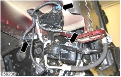
Disconnect the electrical connectors of the left-hand and right-hand rear wheel speed sensors. - Detach the wiring harness from the clamp.
- Disconnect the electrical connector.
| | | -
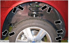
Detach the wheel speed sensors wiring harness from the rear suspension. - Release the cable from the protective sleeve.
- Detach the cable from the clamps.
| | | -
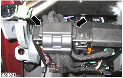
Remove the clip nuts of the rear exhaust heat shield. - Pull the exhaust heat shield downwards.
| | | -
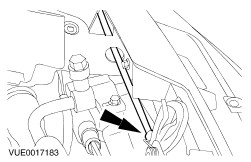
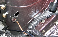
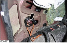
Disconnect the headlamp leveling rear sensor connector. | | | -
Disconnect the fuel powered booster heater electrical connector (if equipped). - Unclip the wiring harness.
| | | -
Remove the engine undershield (if equipped). | | | -
Remove the right-hand and left-hand front wheelhouse covers (left-hand side shown). | | | -
Disconnect the right-hand and left-hand front wheel speed sensor electrical connectors (left-hand side shown). - Slide the wiring harness into the engine compartment.
| | | -
Disconnect the connector of the cruise control system vacuum pump. | | | -
Remove the right- and left-hand turn signal side repeater lamps. - Pull the turn signal lamp out of the fender and detach the lamp holder from the turn signal lamp.
- Detach the wiring harness from the wheelhouse and slide it into the engine compartment.
| | | -
Disconnect the electrical connectors of the ambient temperature sensor, windshield/rear window washer pump, headlamp washer system pump and washer fluid reservoir level gauge. - Unclip the washer fluid reservoir wiring harness from the washer fluid reservoir and the side member.
| | | -
Disconnect the electrical connectors of the refrigerant high pressure switch and the signal horns. | | | -
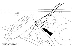
Disconnect the headlamp leveling front sensor connector. - Unclip the wiring harness.
| | | -
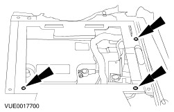
Remove the heater housing.
For additional information, refer to: Heizungsgehäuse (412-02A, Removal and Installation).
| | | -
Remove the generic electronic module (GEM) wiring harness cover. | | | -
Disconnect the connector from the GEM. | | | -
Disconnect the hood latch release cable from the hood latch. | | | -
Detach the battery distribution box from the front panel. | | | -
Detach the battery front cover from the battery carrier and front panel. | | | -
Disconnect the radiator fan connector. - Detach the connector from the radiator fan cowling.
| | | -
Remove the hydraulic control unit (HCU).
For additional information, refer to: Hydraulische Regeleinheit (HCU) (206-09A, Removal and Installation).
| | | -
Disconnect the coolant level switch electrical connector. | | | -
Disconnect the engine wiring harness connector. - Release the engine wiring harness from the battery tray.
| | | -
Detach the wiring harness bracket from the battery carrier. | | | -
Remove the battery side cover. | | | -
Remove the battery carrier. | | | -
Open the cover of the battery junction box. | | | -
Detach the voltage supply cable from the battery junction box. | | | -
Detach the main wiring harness connector from the battery junction box. | | | -
Detach the main wiring harness ground cable from the battery clamp. | | | -
Disconnect the engine wiring harness electrical connector from the engine compartment wiring harness. - Pull the engine wiring harness electrical connector out of the bracket.
| | | -
Remove the engine wiring harness electrical connector bracket. - Detach the main wiring harness ground cable from the side member.
| | | -
Detach the main wiring harness ground cable from the left-hand strut mount reinforcement. - Unclip the main wiring harness.
| | | -
Disconnect the heater control valve electrical connector. | | | -
Disconnect the anti-theft alarm horn electrical connector. | | | -
Remove the hood contact switch cover. | | | -
Disconnect the hood contact switch connector. - Unclip the main wiring harness.
| | | -
Disconnect the electrical connectors for the brake booster and brake master cylinder. - Unclip the main wiring harness.
| | | -
Disconnect the brake fluid level warning lamp switch electrical connector and the additional coolant pump electrical connector. - Unclip the main wiring harness.
| | | -
Disconnect the accelerator pedal position sensor electrical connector (only vehicles with 2.0L or 2.3L engine). | | | -
Detach the additional coolant pump from the bulkhead. | | | -
Disconnect the EVAP canister vent solenoid valve electrical connector. | | | -
Detach the EVAP canister vent solenoid valve together with bracket from the bulkhead. | | | -
Detach the front panel from the front fender. - Pull the front panel forwards.
| | | -
Detach the main wiring harness ground cable from the side member. | | | -
Unclip the main wiring harness from the side member. - Slide the wiring harness into the engine compartment.
- Unclipt the main wiring harness from the right-hand strut mount reinforcement.
| | | -
Unclip the wiring harness right-hand bracket from the bulkhead. - Unclip the brake line from the bulkhead.
| | | -
Unclip the wiring harness left-hand bracket from the bulkhead. - Unclip the brake line from the bulkhead.
- Slide the main wiring harness through the bulkhead aperture.
| | | -
Remove the luggage compartment blind (if equipped). | Vehicles with rear multimedia system | | -
Remove the multimedia system control unit. For additional information, refer to: (415-07 ) Steuergerät - Video-System - Fahrzeuge nicht ausgestattet mit DVD-Spieler/DVD-Spieler (Removal and Installation), Steuergerät - Video-System - Fahrzeuge ausgestattet mit DVD-Spieler (Removal and Installation). | | | -
Detach the luggage compartment tool pocket cover and open the video unit storage pocket. | | | -
Disconnect the video unit electrical connector. | All vehicles | | -
Disconnect the brake pedal position switch electrical connector and the clutch pedal position sensor electrical connector. | | | -
Disconnect the accelerator pedal position sensor electrical connector (only vehicles with 2.8L or diesel engine). | | | -
Detach the powertrain control module (PCM) electrical connector from the PCM. | | | -
Disconnect the overhead console wiring harness electrical connector from the main wiring harness. | | | -
Remove the front seats.
For additional information, refer to: Vordersitz (501-10, Removal and Installation).
| | | -
Remove the right and left-hand side trim.
For additional information, refer to: Seitenverkleidung (501-05, Removal and Installation).
| | | -
Remove the load space left-hand trim panel.
For additional information, refer to: Linke Verkleidung - Laderaum (501-05, Removal and Installation).
| | | -
Remove the load space right-hand trim panel.
For additional information, refer to: Rechte Verkleidung - Laderaum (501-05, Removal and Installation).
| | | -
Remove the centre console cover. | | | -
Remove the centre console insert. | | | -
Remove the floor covering clips. | | | -
Remove the floor covering trim. | | | -
Remove the righ-hand and left-hand trim of the seat console. | | | -
Disconnect the positive cable of the additional battery (if equipped). | | | -
Remove the right-hand and left-hand brackets of the side trim. | | | -
Remove the rear seat mounting trim. | | | -
Remove the fuel pump cover. | | | -
Disconnect the fuel pump electrical connector. | | | -
Detach the wiring harness rubber grommets from the floor pan. - Pull the wiring harness into the passenger compartment.
| | | -
Remove the upper trim of the handbrake lever. - Pull the trim upwards.
- Pull out the trim.
| | | -
Remove the lower trim of the handbrake lever. - Partly fold the front carpet forwards.
| | | -
Disconnect the handbrake lever warning lamp switch electrical connector. | | | -
Disconnect the center console wiring harness connector. - Disconnect the selector lever position display bulb electrical connector.
- Disconnect the selector lever interlock actuator electrical connector.
| | | -
Remove the rear footwell air duct nuts. - Raise the rear footwell air duct, unclip the center console wiring harness and pull it out.
| | | -
Detach the main wiring harness ground cable from the floor pan on the left-hand and right-hand sides (left-hand side shown). | | | -
Disconnect the electrical connector of the parking aid front loudspeaker. | | | -
Disconnect the parking aid module electrical connector. | | | -
Disconnect the yaw rate sensor electrical connector. | | | -
Disconnect the right-hand and left-hand front side crash sensor electrical connectors (left-hand side shown). - Unclip the wiring harnesses.
| | | -
Disconnect the right-hand and left-hand rear side crash sensor electrical connectors (if equipped, left-hand side shown). | | | -
Remove the air duct of the face level ventilation nozzles. - Cut the cable ties.
- Remove the bolt.
| | | -
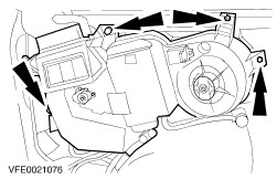
Disconnect the electrical connectors of the additional blower motor, additional blower motor resistor, temperature control flap actuator and air distribution flap actuator. - Disconnect the water drain hose.
| | | -
Detach the additional heat exchanger housing from the side panel. | | | -
Disconnect the right-hand and left-hand rear lamp unit electrical connectors (right-hand side shown). | | | -
Disconnect the electrical connector of the parking aid rear loudspeaker. | | | -
Disconnect the electrical connector of the parking aid rear sensors. | | | -
Disconnect the rear window washer system pump hose. | | | -
Unclip the main wiring harness behind the additional heat exchanger housing. - Pull out the main wiring harness.
| | | -
Disconnect the tailgate wiring harness electrical connector from the main wiring harness. - Unclip the main wiring harness sockets from the brackets.
| | | -
Detach the main wiring harness ground cable from the side panel on the left-hand and right-hand sides (right-hand side shown). | | | -
Disconnect the tank filler flap unlocking switch electrical connector. - Unclip the main wiring harness socket and wiring harness from the wheelhouse.
| | | -
Detach the right-hand and left-hand rear door contact switches from the C-pillars and disconnect the electrical connectors (left-hand side shown). | | | -
Remove the right-hand and left-hand B-pillar covers (left-hand side shown). - Remove the B-pillar pre-formed damping element.
| | | -
Disconnect the right-hand and left-hand front and rear door wiring harness electrical connectors from the main wiring harness (left-hand side shown). - Turn the bayonet fixing counter-clockwise.
| | | -
Detach the right-hand and left-hand main wiring harness sockets from the A- and B-pillars (left-hand side shown). - Turn the outer ring counter-clockwise.
| | | -
Disconnect the right-hand and left-hand front door contact switch electrical connectors (left-hand side shown). | | | -
Unclip the main wiring harness from the right-hand and left-hand side sills. - Slide the main wiring harness through the bulkhead aperture.
| | | -
Remove the main wiring harness with the help of a second technician. | Installation | | -
Install the components in reverse order. | |