ford Workshop Repair Guides

Ford Workshop Service and Repair Manuals

419-10 Multifunction Electronic Modules > < Navigation System
Navigation System - Vehicles With: Traffic Pro - Navigation System Galaxy 2000.75 (04/2000-02/2006)
Diagnosis and Testing

Refer to Wiring Diagrams Section 419-07, for schematic and connector information.

Inspection and Verification

  1. Verify the customer concern.
  1. Visually inspect for obvious signs of mechanical or electrical damage.

Visual Inspection Chart

Mechanical Electrical
Global positioning system (GPS) antenna Fuse(s)
CD ROM Wiring harness
Navigation system display module Electrical connector(s)
Navigation system display module
  1. If an obvious cause for an observed or reported concern is found, correct the cause (if possible) before proceeding to the next step.
  1. If the cause is not visually evident, verify the symptom and refer to Symptom Chart.

Symptom Chart

Symptom Chart

Symptom Possible Sources Action
Navigation system does not operate but radio does
*
Incorrectly installed CD ROM.
*
Install the CD ROM correctly.
Navigation system will not switch on
*
Fuse(s).
*
Circuit(s).
*
Navigation system display module.
*
GO to Pinpoint Test A. .
Navigation system does not operate correctly
*
GPS antenna signal.
*
Reversing lamp(s) signal.
*
Vehicle speed sensor (VSS) signal.
*
Navigation system display module internal sensors.
*
REFER to Calibration.
*
VSS.
*
Reversing lamp(s).
*
GO to Pinpoint Test B. .
NOTE:
NOTE:If the navigation system display module power supply is disconnected it will require the security code to be entered for the system to operate.
NOTE:
NOTE:It is necessary to carry out part of the system diagnosis outside of the workshop. Make sure there are no large buildings/obstructions or metal objects in the immediate vicinity.

When a new navigation system display module is installed the system must be calibrated. For additional information. Go to Calibration.

Calibration

When the navigation system display module is switched ON, four different display messages may appear referring to the GPS antenna and signal:

  • GPS OK - The CD ROM maybe installed to the navigation system display module.
  • GPS WAIT - The navigation system is waiting to receive all of the necessary satellites signals in order to allow the system to display GPS OK.
  • GPS ANTENNE ERROR - The GPS antenna is not connected to the navigation system display module or the GPS antenna is out of order.
  • GPS MODUL ERROR - If this message appears, contact the hotline for further information.

After the CD ROM is installed, PRESS the NAV button.

The language selection will be displayed. To select the language required, TURN the right-hand rotary knob. Then PRESS the right-hand rotary knob to confirm selection.

After the language has been selected the navigation system display module will give a choice of male or female voice to give the driver navigation instructions (this is only available for some of the languages).

To select the required voice, TURN the right-hand rotary knob, then PRESS the right-hand rotary knob to confirm selection.

To confirm all language and voice selections, PRESS the right-hand rotary knob.

The navigation system display module will now display:

  • PLEASE WAIT FOR GPS RECEPTION! CALIBRATION-RIDE NOT POSSIBLE

Service Garage Mode

NOTE:
NOTE:Before commencing the calibration-ride the SENSOR TEST in the SERVICE GARAGE MODE should be carried out.

To access the SERVICE GARAGE MODE, PRESS the NAV button twice.

PRESS and HOLD the multifunction button 3. PRESS the multifunction button 5.

The navigation system display module will now display the following:

  • CALIBRATION RIDE - The vehicle must be driven on a road with several changes in direction.
  • GPS INFO - GPS function test. If the GPS reception is functioning correctly, the number of satellites received, the date and time and type of location (example 3D) is displayed.
  • CALIBRATION - Function for deleting the calibration settings or a calibration specification.
  • SENSORS - Sensor function test. This function displays the values of the VSS, reverse sensor and internal sensors. Move the vehicle ten metres forwards and rearwards to make the values change.
  • VERSION - Displays status of the current CD ROM.
  • SPEECH TEST - Voice test. Select this function and the announcement "Please insert navigation CD" will be given.
  • MODULE TEST - Internal component test of the navigation system display module.
  • DEMO - Demo mode selection.
NOTE:
NOTE:Calibration settings must be entered only when they are known. If incorrect values are entered the navigation system display module cannot make correct navigation calculations.
NOTE:
NOTE:To exit the DEMO function, select OFF with the right-hand rotary knob, then PRESS the right-hand rotary to confirm.

TURN the right-hand rotary knob to select the required function, then PRESS the right-hand rotary knob to confirm.

To exit the function required, PRESS the NAV button to return to the SERVICE GARAGE MODE.

Pinpoint Tests

PINPOINT TEST A : NAVIGATION SYSTEM WILL NOT SWITCH ON

TEST CONDITIONS DETAILS/RESULTS/ACTIONS
A1: CHECK FOR VOLTAGE TO NAVIGATION SYSTEM DISPLAY MODULE (RD)
1
Disconnect Navigation System Display Module.
2
Ignition switch in position II.

3
Measure the voltage between the navigation system display module pin 4, (RD), harness side and ground.

Is the voltage greater than 10 volts?
Yes
No
A2: CHECK FOR VOLTAGE TO NAVIGATION SYSTEM DISPLAY MODULE (BK)
1
Ignition switch in position II.

2
Measure the voltage between the navigation system display module pin 7, (BK), harness side and ground.

Is the voltage greater than 10 volts?
Yes
No
A3: CHECK THE NAVIGATION SYSTEM DISPLAY MODULE (BN) TO GROUND

1
Measure the resistance between the navigation system display module pin 8, (BN), harness side and ground.

Is the resistance less than 5 ohms?
Yes
INSTALL a new navigation system display module. TEST the system for normal operation.
No
REPAIR the circuit. TEST the system for normal operation.
A4: CHECK CENTRAL JUNCTION BOX (CJB) (RD) TO NAVIGATION SYSTEM DISPLAY MODULE (RD) FOR OPEN
1
Disconnect CJB C8.

2
Measure the resistance between the CJB C8 pin 60, (RD), harness side and the navigation system display module pin 4, (RD), harness side.

Is the resistance less than 5 ohms?
Yes
No
REPAIR the circuit(s). TEST the system for normal operation.
A5: CHECK CJB (BN/RD) TO NAVIGATION SYSTEM DISPLAY MODULE (BK) FOR OPEN

1
Measure the resistance between the CJB C8 pin 62, (BN/RD), harness side and the navigation system display module pin 7, (BK), harness side.

Is the resistance less than 5 ohms?
Yes
INSTALL a new navigation system display module. TEST the system for normal operation.
No
REPAIR the circuit(s). TEST the system for normal operation.

PINPOINT TEST B : NAVIGATION SYSTEM DOES NOT OPERATE CORRECTLY

TEST CONDITIONS DETAILS/RESULTS/ACTIONS
B1: CHECK THE VSS SIGNAL TO THE NAVIGATION SYSTEM DISPLAY MODULE (WH/BU)
1
Disconnect Navigation System Display Module.
2
Ignition switch in position II.

3
Measure the voltage between the navigation system display module pin 1, (WH/BU), harness side and ground.
4
Drive the vehicle for several miles at various speeds.

Is the voltage between 5 - 16 volts while the vehicle is being driven?
Yes
No
Vehicles with 2.0L or 2.3L engine, GO to B2. .Vehicles with 2.8L engine with manual transaxle, GO to B3. .Vehicles with 2.8L engine with automatic transaxle, GO to B4. .Vehicles with diesel engine with manual transaxle, GO to B5. .Vehicles with diesel engine with automatic transaxle, GO to B6. .
B2: CHECK THE POWERTRAIN CONTROL MODULE (PCM) (VT) TO THE NAVIGATION SYSTEM DISPLAY MODULE (WH/BU) FOR OPEN
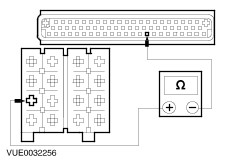
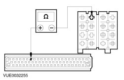
1
Disconnect PCM C53.

2
Measure the resistance between the navigation system display module pin 1, (WH/BU), harness side and the PCM C53 pin 58, (WH/BU), harness side.

Is the resistance less than 5 ohms?
Yes
REFER to WDS.
No
REPAIR the circuit(s). TEST the system for normal operation.
B3: CHECK THE PCM (VT) TO THE NAVIGATION SYSTEM DISPLAY MODULE (WH/BU) FOR OPEN
1
Disconnect PCM C51b.

2
Measure the resistance between the navigation system display module pin 1, (WH/BU), harness side and the PCM C51b pin 54, (VT), harness side.

Is the resistance less than 5 ohms?
Yes
REFER to WDS.
No
REPAIR the circuit(s). TEST the system for normal operation.
B4: CHECK THE AUDIO UNIT (VT) TO THE NAVIGATION SYSTEM DISPLAY MODULE (WH/BU) FOR OPEN
1
Disconnect Audio unit C413.

2
Measure the resistance between the navigation system display module pin 1, (WH/BU), harness side and the audio unit C413 pin 6, (VT), harness side.

Is the resistance less than 5 ohms?
Yes
REFER to WDS.
No
REPAIR the circuit(s). TEST the system for normal operation.
B5: CHECK THE PCM (VT) TO THE NAVIGATION SYSTEM DISPLAY MODULE (WH/BU) FOR OPEN
1
Disconnect PCM C52b.

2
Measure the resistance between the navigation system display module pin 1, (WH/BU), harness side and the PCM C52b pin 20, (VT), harness side.

Is the resistance less than 5 ohms?
Yes
REFER to WDS.
No
REPAIR the circuit(s). TEST the system for normal operation.
B6: CHECK THE AUDIO UNIT (VT) TO THE NAVIGATION SYSTEM DISPLAY MODULE (WH/BU) FOR OPEN
1
Disconnect Audio Unit C413.

2
Measure the resistance between the navigation system display module pin 1, (WH/BU), harness side and the audio unit C413 pin 6, (VT), harness side.

Is the resistance less than 5 ohms?
Yes
REFER to WDS.
No
REPAIR the circuit(s). TEST the system for normal operation.
B7: CHECK THE REVERSE LAMP SIGNAL TO THE NAVIGATION SYSTEM DISPLAY MODULE (VT/BN)
1
Disconnect Navigation System Display Module.
2
Ignition switch in position II.
3
Select reverse gear.

4
Measure the voltage between the navigation system display module pin 2, (VT/BN), harness side and ground.

Is the voltage greater than 10 volts?
Yes
INSTALL a new navigation system display module. TEST the system for normal operation.
No
For vehicles with automatic transaxle, GO to B8. .
For vehicles with 5 speed manual transaxle, GO to B9. .
For vehicles with 6 speed manual transaxle, GO to B10. .
B8: CHECK THE REVERSING LAMP (BK/BU) TO THE NAVIGATION SYSTEM DISPLAY MODULE (VT/BN) FOR OPEN
1
Disconnect CJB C17.

2
Measure the resistance between the navigation system display module pin 2, (VT/BN), harness side and the CJB C17 pin 4, (BK/BU), harness side.

Is the resistance less than 5 ohms?
Yes
REFER to Section  417-01 Exterior Lighting.
No
REPAIR the circuit(s). TEST the system for normal operation.
B9: CHECK THE REVERSING LAMP (GN/WH) TO THE NAVIGATION SYSTEM DISPLAY MODULE (VT/BN) FOR OPEN
1
Disconnect Reversing Lamp Switch C151.

2
Measure the resistance between the navigation system display module pin 2, (VT/BN), harness side and the reversing lamp switch C151 pin 2, (GN/WH), harness side.

Is the resistance less than 5 ohms?
Yes
REFER to Section  417-01 Exterior Lighting.
No
REPAIR the circuit(s). TEST the system for normal operation.
B10: CHECK THE REVERSING LAMP (BK/BU) TO THE NAVIGATION SYSTEM DISPLAY MODULE (VT/BN) FOR OPEN
1
Disconnect Reversing Lamp Switch C151.

2
Measure the resistance between the navigation system display module pin 2, (VT/BN), harness side and the reversing lamp switch C151 pin 2, (BK/BU), harness side.

Is the resistance less than 5 ohms?
Yes
REFER to Section  417-01 Exterior Lighting.
No
REPAIR the circuit(s). TEST the system for normal operation.

419-10 Multifunction Electronic Modules > < Navigation System