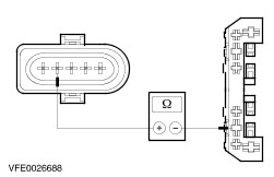
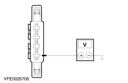
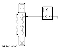
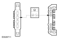
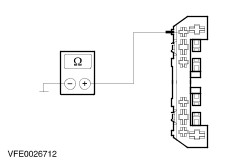
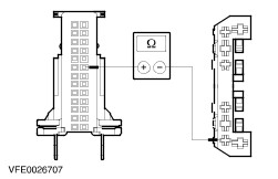
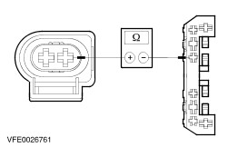
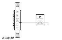
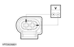
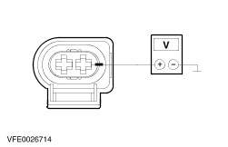
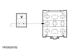
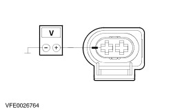
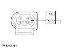
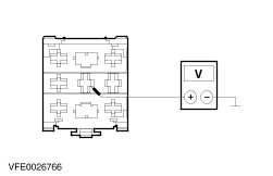
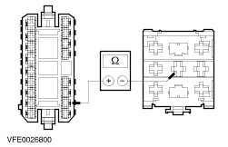
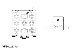
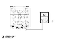
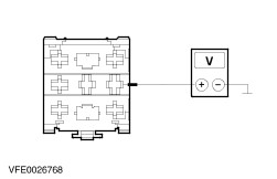
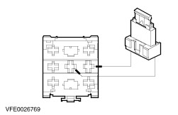
| Diagnosis and Testing Refer to Wiring Diagrams Section 501-16, for schematic and connector information. Special Tool(s) | | Digital Multimeter 105-R0051 or equivalent | | | Terminal probe kit 29-011A | Inspection and Verification - Verify the customer concern.
- Visually inspect for obvious signs of mechanical or electrical damage.
Visual Inspection Chart | Mechanical | Electrical | - Wiper blade(s)
- Wiper arm pivot shaft
- Windshield washer reservoir
- Hose(s)
- Washer nozzles
| - Fuse(s)
- Electrical connector(s)
- Wiring harness
- Washer pump(s)
- Wiper motor(s)
| - If an obvious cause for an observed or reported concern is found, correct the cause (if possible) before proceeding to the next step.
- If the concern is not visually evident, verify the symptom and refer to the Symptom Chart.
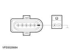
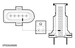
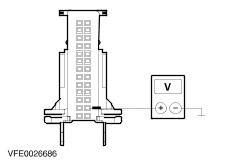
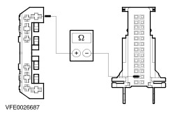
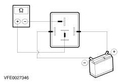
Symptom Chart Symptom Chart | Symptom | Possible Sources | Action | | No communication with the Central Junction Box (CJB) | * Data bus (ISO 9141) * Central Junction Box (CJB) | * | | The wipers are inoperative | * Fuse(s) * Circuit(s) * Multifunction switch * Windshield wiper motor * Rear window wiper motor * Central Junction Box (CJB) | * GO to Pinpoint Test ??. | | The wipers stay on continuously | * Circuit(s) * Multifunction switch * Windshield wiper motor * Rear window wiper motor | * GO to Pinpoint Test ??. | | The high/low wiper speeds does not operate correctly | * Circuit(s) * Multifunction switch * Windshield wiper motor * Central Junction Box (CJB) | * GO to Pinpoint Test ??. | | The intermittent wiper speed does not operate correctly (high/low speeds OK) | * Circuit(s) * Multifunction switch * Central Junction Box (CJB) | * GO to Pinpoint Test ??. | | The wash and wipe function are inoperative | * Circuit(s) * Multifunction switch | * GO to Pinpoint Test ??. | | The wipers will not park at the correct position | * Windshield wiper motor * Rear window wiper motor | * Check the wiper motor, if necessary INSTALL a new one. TEST the system for normal operation. | | The wipers do not operate correctly with the washer function | * Circuit(s) * Rear window wiper motor | * GO to Pinpoint Test ??. | | The washer pump is inoperative (wipe function is OK) | * Circuit(s) * Washer pump motor | * GO to Pinpoint Test ??. | | The headlamp washer function does not operate correctly | * Fuse(s) * Circuit(s) * Headlamp washer pump * Headlamp washer pump relay * Headlamp cleaning relay * Light switch * Central Junction Box (CJB) | * GO to Pinpoint Test ??. | Pinpoint Tests | PINPOINT TEST A : THE WIPERS ARE INOPERATIVE | | TEST CONDITIONS | DETAILS/RESULTS/ACTIONS | | A1: DETERMINE THE FAULT CONDITION | | | 1 Determine the fault condition. | | | Are the windshield wipers inoperative? Yes The rear window wiper and the windshield wipers are inoperative: GO to A2. No The rear window wiper is inoperative: GO to A15. | | A2: CHECK FUSE F20 | | | 1 Ignition switch in position 0. | | | 2 CHECK Fuse F20 (CJB). | | | 3 Check fuse F20 (10 A). | | | Is the fuse OK? Yes No INSTALL a new fuse F20 (10 A). If the fuse blows again, LOCATE and REPAIR the short circuit by using the wiring diagrams. TEST the system for normal operation. | | A3: CHECK THE VOLTAGE AT FUSE F20 | | | 1 Connect Fuse F20 (CJB). | | | 2 Ignition switch in position II. | | | 3 Measure the voltage between fuse F20 (10 A) and ground. | | | Is battery voltage indicated? Yes No REPAIR the power supply of fuse F20 (CJB) by using the wiring diagrams. TEST the system for normal operation. | | A4: CHECK THE VOLTAGE AT THE MULTIFUNCTION SWITCH | | | 1 Ignition switch in position 0. | | | 2 Disconnect Multifunction switch C266. | | | 3 Ignition switch in position II. | | | 4 Measure the voltage between multifunction switch, connector C266, pin 8, circuit (BK/YE), harness side and ground. | | | Is battery voltage indicated? Yes CHECK the multifunction switch according to the Component Test attached to section 417-01 Headlamps, if necessary INSTALL a new one. TEST the system for normal operation. No REPAIR the open circuit, between fuse F20 (CJB) and multifunction switch, by using the wiring diagrams. TEST the system for normal operation. | | A5: CHECK FUSE F24 | | | 1 Ignition switch in position 0. | | | 2 CHECK Fuse F24 (CJB). | | | 3 Check the fuse F24 (30 A). | | | Is the fuse OK? Yes No INSTALL a new fuse F24 (30 A). If the fuse blows again, LOCATE and REPAIR the short circuit by using the wiring diagrams. TEST the system for normal operation. | | A6: CHECK THE VOLTAGE AT FUSE F24 | | | 1 Connect Fuse F24 (CJB). | | | 2 Ignition switch in position II. | | | 3 Measure the voltage between fuse F24 (30 A) and ground. | | | Is battery voltage indicated? Yes No REPAIR the power supply of fuse F24 (CJB) by using the wiring diagrams. TEST the system for normal operation. | | A7: CHECK THE VOLTAGE AT THE WINDSHIELD WIPER MOTOR | | | 1 Ignition switch in position 0. | | | 2 Disconnect Windshield wiper motor C330. | | | 3 Ignition switch in position II. | | | 4 Measure the voltage between windshield wiper motor, connector C330, pin 1, circuit (BK/GY), harness side and ground. | | | Is battery voltage indicated? Yes No REPAIR the open circuit (BK/GY), between windshield wiper motor and fuse F24, by using the wiring diagrams. TEST the system for normal operation. | | A8: CHECK THE VOLTAGE AT THE WIPER MOTOR WITH THE LOW WIPER SPEED ON | | | 1 Turn on the LOW WIPER SPEED. | | | 2 Measure the voltage between windshield wiper motor, connector C330, pin 4, circuit (GN/BK), harness side and ground. | | | Is battery voltage indicated? Yes No | | A9: CHECK THE VOLTAGE AT THE WIPER MOTOR WITH THE HIGH WIPER SPEED ON | | | 1 Turn on the HIGH WIPER SPEED. | | | 2 Measure the voltage between windshield wiper motor, connector C330, pin 2, circuit (BU/YE), harness side and ground. | | | Is battery voltage indicated? Yes No | | A10: CHECK THE GROUND CONNECTION OF THE WINDSHIELD WIPER MOTOR | | | 1 Ignition switch in position 0. | | | 2 Measure the resistance between windshield wiper motor, connector C330, pin 5, circuit (BN), harness side and ground. | | | Is the resistance less than 2 ohms? Yes INSTALL a new windshield wiper motor. TEST the system for normal operation. No REPAIR the open circuit (BN), between windshield wiper motor and ground G2, by using the wiring diagrams. TEST the system for normal operation. | | A11: CHECK THE CIRCUIT (GN/BK) BETWEEN WIPER MOTOR AND CJB FOR OPEN | | | 1 Ignition switch in position 0. | | | 2 Disconnect Central Junction Box (CJB) C2. | | | 3 Measure the resistance between windshield wiper motor, connector C330, pin 4, circuit (GN/BK), harness side and CJB, connector C2, pin 16, circuit (GN/BK), harness side. | | | Is the resistance less than 2 ohms? Yes No REPAIR the open circuit (GN/BK), between windshield wiper motor and CJB, by using the wiring diagrams. TEST the system for normal operation. | | A12: CHECK THE VOLTAGE AT THE CJB WITH THE LOW WIPER SPEED ON | | | 1 Disconnect Central Junction Box (CJB) C1. | | | 2 Ignition switch in position II. | | | 3 Turn on the LOW WIPER SPEED. | | | 4 Measure the voltage between CJB, connector C1, pin 15, circuit (BU), harness side and ground. | | | Is battery voltage indicated? Yes INSTALL a new CJB. TEST the system for normal operation. No | | A13: CHECK THE CIRCUIT (BU) BETWEEN MULTIFUNCTION SWITCH AND CJB FOR OPEN | | | 1 Ignition switch in position 0. | | | 2 Disconnect Multifunction switch C266. | | | 3 Measure the resistance between multifunction switch, connector C266, pin 1, circuit (BU), harness side and CJB, connector C1, pin 15, circuit (BU), harness side. | | | Is the resistance less than 2 ohms? Yes CHECK the multifunction switch according to the Component Test attached to section 417-01 Headlamps, if necessary INSTALL a new one. TEST the system for normal operation. No REPAIR the open circuit (BU), between multifunction switch and CJB, by using the wiring diagrams. TEST the system for normal operation. | | A14: CHECK THE CIRCUIT (BU/YE) BETWEEN MULTIFUNCTION SWITCH AND WIPER MOTOR FOR OPEN | | | 1 Ignition switch in position 0. | | | 2 Disconnect Multifunction switch C266. | | | 3 Measure the resistance between windshield wiper motor, connector C330, pin 2, circuit (BU/YE), harness side and multifunction switch, connector C266, pin 6, circuit (BU/YE), harness side. | | | Is the resistance less than 2 ohms? Yes CHECK the multifunction switch according to the Component Test attached to section 417-01 Headlamps, if necessary INSTALL a new one. TEST the system for normal operation. No REPAIR the open circuit (BU/YE), between windshield wiper motor and multifunction switch, by using the wiring diagrams. TEST the system for normal operation. | | A15: CHECK THE VOLTAGE AT THE REAR WINDOW WIPER MOTOR | | | 1 Ignition switch in position 0. | | | 2 Disconnect Rear window wiper motor C308. | | | 3 Ignition switch in position II. | | | 4 Measure the voltage between rear window wiper motor, connector C308, pin 4, circuit (BK/YE), harness side and ground. | | | Is battery voltage indicated? Yes No REPAIR open circuit (BK/YE), between rear window wiper motor and CJB, by using the wiring diagrams. TEST the system for normal operation. | | A16: CHECK THE GROUND CONNECTION OF THE REAR WINDOW WIPER MOTOR | | | 1 Ignition switch in position 0. | | | 2 Measure the resistance between rear window wiper motor, connector C308, pin 1, circuit (BN), harness side and ground. | | | Is the resistance less than 2 ohms? Yes No REPAIR open circuit (BN), between rear window wiper motor and ground G8, by using the wiring diagrams. TEST the system for normal operation. | | A17: CHECK THE GROUND CONNECTION OF THE WIPER MOTOR WITH THE REAR WIPER ON | | | 1 Turn on the REAR WINDOW WIPER. | | | 2 Measure the resistance between rear window wiper motor, connector C308, pin 2, circuit (GN/RD), harness side and ground. | | | Is the resistance less than 2 ohms? Yes CHECK the rear window wiper motor, if necessary INSTALL a new one. TEST the system for normal operation. No | | A18: CHECK THE CIRCUIT (GN/RD) RESP. (GN/YE) BETWEEN WIPER MOTOR AND MULTIFUNCTION SWITCH FOR OPEN | | | 1 Disconnect Multifunction switch C266. | | | 2 Measure the resistance between rear window wiper motor, connector C308, pin 2, circuit (GN/RD), harness side and multifunction switch, connector C266, pin 4, circuit (GN/YE), harness side. | | | Is the resistance less than 2 ohms? Yes No REPAIR open circuit (GN/RD) resp. (GN/YE), between rear window wiper motor and multifunction switch, by using the wiring diagrams. TEST the system for normal operation. | | A19: CHECK THE GROUND CONNECTION OF THE MULTIFUNCTION SWITCH | | | 1 Measure the resistance between multifunction switch, connector C266, pin 2, circuit (BN), harness side and ground. | | | Is the resistance less than 2 ohms? Yes CHECK the multifunction switch according to the Component Test attached to section 417-01 Headlamps, if necessary INSTALL a new one. TEST the system for normal operation. No REPAIR open circuit (BN), between multifunction switch and ground G5 (LHD) resp. G9 (RHD), by using the wiring diagrams. TEST the system for normal operation. | | PINPOINT TEST B : THE WIPERS STAY ON CONTINUOUSLY | | TEST CONDITIONS | DETAILS/RESULTS/ACTIONS | | B1: CHECK THE SYSTEM BY USING THE WDS | | | 1 Connect the diagnostic tool. | | | 2 Check the system by using the WDS. | | | Are any error-codes (DTC's) indicated? Yes WORK through the DTC's, according to the WDS instruction. CLEAR the error memory and TEST the system for normal operation. No | | B2: DETERMINE THE FAULT CONDITION | | | 1 Determine the fault condition. | | | Are the windshield wipers on continuously? Yes No | | B3: CHECK THE VOLTAGE AT THE WINDSHIELD WIPER MOTOR (SHORT TO POWER) | | | 1 Ignition switch in position 0. | | | 2 Disconnect Windshield wiper motor C330. | | | 3 Ignition switch in position II. | | | 4 Measure the voltage between windshield wiper motor, connector C330, pin 2, circuit (BU/YE), harness side and ground. | | | Is battery voltage indicated? Yes No | | B4: CHECK THE CIRCUIT (BU/YE) FOR SHORT TO POWER | | | 1 Ignition switch in position 0. | | | 2 Disconnect Multifunction switch C266. | | | 3 Ignition switch in position II. | | | 4 Measure the voltage between windshield wiper motor, connector C330, pin 2, circuit (BU/YE), harness side and ground. | | | Is battery voltage indicated? Yes LOCATE and REPAIR the short to power in circuit (BU/YE), by using the wiring diagrams. TEST the system for normal operation. No CHECK the multifunction switch according to the Component Test attached to section 417-01 Headlamps, if necessary INSTALL a new one. TEST the system for normal operation. | | B5: CHECK THE CIRCUIT (GN/BK) FOR SHORT TO POWER | | | 1 Measure the voltage between windshield wiper motor, connector C330, pin 4, circuit (GN/BK), harness side and ground. | | | Is battery voltage indicated? Yes No CHECK the windshield wiper motor, if necessary INSTALL a new one. TEST the system for normal operation. | | B6: CHECK THE VOLTAGE AT THE WIPER MOTOR (SHORT TO POWER) | | | 1 Ignition switch in position 0. | | | 2 Disconnect Multifunction switch C266. | | | 3 Ignition switch in position II. | | | 4 Measure the voltage between windshield wiper motor, connector C330, pin 4, circuit (GN/BK), harness side and ground. | | | Is battery voltage indicated? Yes Constant voltage: LOCATE and REPAIR the short to power in circuit (BU), connected with multifunction switch, connector C266, pin 1, by using the wiring diagrams. TEST the system for normal operation. Alternating voltage: LOCATE and REPAIR the short to power in circuit (BN/YE), connected with multifunction switch, connector C266, pin 7, by using the wiring diagrams. TEST the system for normal operation. No CHECK the multifunction switch according to the Component Test attached to section 417-01 Headlamps, if necessary INSTALL a new one. TEST the system for normal operation. | | B7: CHECK THE RESISTANCE AT THE REAR WINDOW WIPER MOTOR FOR SHORT TO GROUND | | | 1 Ignition switch in position 0. | | | 2 Disconnect Rear window wiper motor C308. | | | 3 Measure the resistance between rear window wiper motor, connector C308, pin 2, circuit (GN/YE), harness side and ground. | | | Is the resistance greater than 10 kohms? Yes CHECK the rear window wiper motor, if necessary INSTALL a new one. TEST the system for normal operation. No | | B8: CHECK THE CIRCUIT (GN/YE) RESP. (GN/RD) FOR SHORT TO GROUND | | | 1 Disconnect Multifunction switch C266. | | | 2 Measure the resistance between rear window wiper motor, connector C308, pin 2, circuit (GN/YE), harness side and ground. | | | Is the resistance greater than 10 kohms? Yes CHECK the multifunction switch according to the Component Test attached to section 417-01 Headlamps, if necessary INSTALL a new one. TEST the system for normal operation. No LOCATE and REPAIR the short to ground in circuits (GN/YE) resp. (GN/RD), connected with splice S94, by using the wiring diagrams. TEST the system for normal operation. | | PINPOINT TEST C : THE HIGH/LOW WIPER SPEEDS DOES NOT OPERATE CORRECTLY | | TEST CONDITIONS | DETAILS/RESULTS/ACTIONS | | C1: CHECK THE SYSTEM BY USING THE WDS | | | 1 Connect the diagnostic tool. | | | 2 Check the system by using the WDS. | | | Are any error-codes (DTC's) indicated? Yes WORK through the DTC's, according to the WDS instruction. CLEAR the error memory and TEST the system for normal operation. No | | C2: DETERMINE THE FAULT CONDITION | | | 1 Ignition switch in position II. | | | 2 Turn through ALL WIPER SPEEDS (INTERMITTENT / LOW / HIGH). | | | 3 CHECK the windshield wipers. | | | Do the windshield wipers operate in low wiper speed mode? Yes High wiper speed is inoperative: GO to C5. No Intermittent wipe mode is inoperative: GO to C7. | | C3: CHECK THE VOLTAGE AT THE CJB WITH THE LOW WIPER SPEED ON | | | 1 Ignition switch in position 0. | | | 2 Disconnect Central Junction Box (CJB) C1. | | | 3 Ignition switch in position II. | | | 4 Turn on the LOW WIPER SPEED. | | | 5 Measure the voltage between CJB, connector C1, pin 15, circuit (BU), harness side and ground. | | | Is battery voltage indicated? Yes CHECK the Central Junction Box (CJB), if necessary INSTALL a new one. TEST the system for normal operation. No | | C4: CHECK THE CIRCUIT (BU) BETWEEN MULTIFUNCTION SWITCH AND CJB FOR OPEN | | | 1 Ignition switch in position 0. | | | 2 Disconnect Multifunction switch C266. | | | 3 Measure the resistance between multifunction switch, connector C266, pin 1, circuit (BU), harness side and CJB, connector C1, pin 15, circuit (BU), harness side. | | | Is the resistance less than 2 ohms? Yes CHECK the multifunction switch according to the Component Test attached to section 417-01 Headlamps, if necessary INSTALL a new one. TEST the system for normal operation. No REPAIR the open circuit (BU), between CJB and multifunction switch, by using the wiring diagrams. TEST the system for normal operation. | | C5: CHECK THE VOLTAGE AT THE WIPER MOTOR WITH THE HIGH WIPER SPEED ON | | | 1 Ignition switch in position 0. | | | 2 Disconnect Windshield wiper motor C330. | | | 3 Ignition switch in position II. | | | 4 Turn on the HIGH WIPER SPEED. | | | 5 Measure the voltage between windshield wiper motor, connector C330, pin 2, circuit (BU/YE), harness side and ground. | | | Is battery voltage indicated? Yes CHECK the windshield wiper motor, if necessary INSTALL a new one. TEST the system for normal operation. No | | C6: CHECK THE CIRCUIT (BU/YE) FOR OPEN | | | 1 Ignition switch in position 0. | | | 2 Disconnect Multifunction switch C266. | | | 3 Measure the resistance between windshield wiper motor, connector C330, pin 2, circuit (BU/YE), harness side and multifunction switch, connector C266, pin 6, circuit (BU/YE), harness side. | | | Is the resistance less than 2 ohms? Yes CHECK the multifunction switch according to the Component Test attached to section 417-01 Headlamps, if necessary INSTALL a new one. TEST the system for normal operation. No REPAIR the open circuit (BU/YE), between wiper motor and multifunction switch, by using the wiring diagrams. TEST the system for normal operation. | | C7: CHECK THE VOLTAGE AT THE WIPER MOTOR WITH THE LOW WIPER SPEED ON | | | 1 Ignition switch in position 0. | | | 2 Disconnect Windshield wiper motor C330. | | | 3 Ignition switch in position II. | | | 4 Turn on the LOW WIPER SPEED. | | | 5 Measure the voltage between windshield wiper motor, connector C330, pin 4, circuit (GN/BK), harness side and ground. | | | Is battery voltage indicated? Yes CHECK the windshield wiper motor, if necessary INSTALL a new one. TEST the system for normal operation. No REPAIR the open circuit (GN/BK), between CJB and windshield wiper motor, by using the wiring diagrams. TEST the system for normal operation. | | PINPOINT TEST D : THE INTERMITTENT WIPER SPEED DOES NOT OPERATE CORRECTLY (HIGH/LOW SPEEDS OK) | | TEST CONDITIONS | DETAILS/RESULTS/ACTIONS | | D1: CHECK THE VOLTAGE AT THE CJB WITH THE INTERMITTENT WIPE ON | | | 1 Ignition switch in position 0. | | | 2 Disconnect Central Junction Box (CJB) C1. | | | 3 Ignition switch in position II. | | | 4 Turn on the INTERMITTENT WIPE. | | | 5 Measure the voltage between CJB, connector C1, pin 21, circuit (BN/YE), harness side and ground. | | | Is battery voltage indicated? Yes CHECK the CJB, if necessary INSTALL a new one. TEST the system for normal operation. No | | D2: CHECK THE CIRCUIT (BN/YE) BETWEEN MULTIFUNCTION SWITCH AND CJB FOR OPEN | | | 1 Ignition switch in position 0. | | | 2 Disconnect Multifunction switch C266. | | | 3 Measure the resistance between CJB, connector C1, pin 21, circuit (BN/YE), harness side and multifunction switch, connector C266, pin 7, circuit (BN/YE), harness side. | | | Is the resistance less than 2 ohms? Yes CHECK the multifunction switch according to the Component Test attached to section 417-01 Headlamps, if necessary INSTALL a new one. TEST the system for normal operation. No REPAIR the open circuit (BN/YE), between CJB and multifunction switch, by using the wiring diagrams. TEST the system for normal operation. | | PINPOINT TEST E : THE WASH AND WIPE FUNCTION ARE INOPERATIVE | | TEST CONDITIONS | DETAILS/RESULTS/ACTIONS | | E1: CHECK THE SYSTEM BY USING THE WDS | | | 1 Connect the diagnostic tool. | | | 2 Check the system by using the WDS. | | | Are any error-codes (DTC's) indicated? Yes WORK through the DTC's, according to the WDS instruction. CLEAR the error memory and TEST the system for normal operation. No | | E2: CHECK THE REAR WINDOW WIPER | | | 1 Turn on the REAR WINDOW WIPER. | | | 2 Check the rear window wiper. | | | Does the rear window wiper operate correctly? Yes CHECK the multifunction switch according to the Component Test attached to section 417-01 Headlamps, if necessary INSTALL a new one. TEST the system for normal operation. No | | E3: CHECK THE GROUND CONNECTION OF THE WIPER MOTOR WITH THE REAR WIPER ON | | | 1 Ignition switch in position 0. | | | 2 Disconnect Rear window wiper motor C308. | | | 3 Turn on the REAR WINDOW WIPER. | | | 4 Measure the resistance between rear window wiper motor, connector C308, pin 2, circuit (GN/RD), harness side and ground. | | | Is the resistance less than 2 ohms? Yes No | | E4: CHECK THE CIRCUIT (GN/YE) BETWEEN MULTIFUNCTION SWITCH AND SPLICE S94 FOR OPEN | | | 1 Disconnect Multifunction switch C266. | | | 2 Measure the resistance between rear window wiper motor, connector C308, pin 2, circuit (GN/YE), harness side and multifunction switch, connector C266, pin 4, circuit (GN/YE), harness side. | | | Is the resistance less than 2 ohms? Yes No REPAIR open circuit (GN/YE), between multifunction switch and splice S94, by using the wiring diagrams. TEST the system for normal operation. | | E5: CHECK THE GROUND CONNECTION OF THE MULTIFUNCTION SWITCH | | | 1 Measure the resistance between multifunction switch, connector C266, pin 2, circuit (BN), harness side and ground. | | | Is the resistance less than 2 ohms? Yes CHECK the multifunction switch according to the Component Test attached to section 417-01 Headlamps, if necessary INSTALL a new one. TEST the system for normal operation. No REPAIR open circuit (BN), between multifunction switch and ground G5 (LHD) resp. G9 (RHD), by using the wiring diagrams. TEST the system for normal operation. | | E6: CHECK THE CIRCUIT (BN/YE) BETWEEN MULTIFUNCTION SWITCH AND SPLICE S93 FOR OPEN | | | 1 Disconnect Multifunction switch C266. | | | 2 Measure the resistance between rear window wiper motor, connector C308, pin 3, circuit (BN/YE), harness side and multifunction switch, connector C266, pin 5, circuit (BN/YE), harness side. | | | Is the resistance less than 2 ohms? Yes CHECK the multifunction switch according to the Component Test attached to section 417-01 Headlamps, if necessary INSTALL a new one. TEST the system for normal operation. No REPAIR the open circuit (BN/YE), between multifunction switch and splice S93, by using the wiring diagrams. TEST the system for normal operation. | | PINPOINT TEST F : THE WIPERS DO NOT OPERATE CORRECTLY WITH THE WASHER FUNCTION | | TEST CONDITIONS | DETAILS/RESULTS/ACTIONS | | F1: CHECK THE SYSTEM BY USING THE WDS | | | 1 Connect the diagnostic tool. | | | 2 Check the system by using the WDS. | | | Are any error-codes (DTC's) indicated? Yes WORK through the DTC's, according to the WDS instruction. CLEAR the error memory and TEST the system for normal operation. No | | F2: DETERMINE THE FAULT CONDITION | | | 1 Determine the fault condition. | | | Do the windshield wipers not operate with the washer function? Yes No | | F3: CHECK THE VOLTAGE AT THE REAR WINDOW WIPER MOTOR WITH THE REAR WASHER ON | | | 1 Ignition switch in position II. | | | 2 Turn on the REAR WASHER. | | | 3 Measure the voltage between rear window wiper motor, connector C308, pin 3, circuit (BN/YE), harness side and ground. | | | Is battery voltage indicated? Yes CHECK the rear window wiper motor, if necessary INSTALL a new one. TEST the system for normal operation. No REPAIR the open circuit (BN/YE), between rear window wiper motor and splice S93, by using the wiring diagrams. TEST the system for normal operation. | | F4: CHECK THE VOLTAGE AT THE CJB WITH THE WINDSHIELD WASHER ON | | | 1 Ignition switch in position 0. | | | 2 Disconnect Central Junction Box (CJB) C1. | | | 3 Ignition switch in position II. | | | 4 Turn on the WINDSHIELD WASHER. | | | 5 Measure the voltage between CJB, connector C1, pin 11, circuit (GN/YE), harness side and ground. | | | Is battery voltage indicated? Yes CHECK the CJB, if necessary INSTALL a new one. TEST the system for normal operation. No REPAIR the open circuit (GN/YE), between splice S94 and CJB, connector C1, pin 11, by using the wiring diagrams. TEST the system for normal operation. | | PINPOINT TEST G : THE WASHER PUMP IS INOPERATIVE (WIPE FUNCTION IS OK) | | TEST CONDITIONS | DETAILS/RESULTS/ACTIONS | | G1: CHECK THE WASHER PUMP MOTOR | | | 1 Ignition switch in position 0. | | | 2 Disconnect Washer pump motor C374. | | | 3 Ignition switch in position II. | | | 4 Turn on the WINDSHIELD WASHER. | | | 5 Measure the voltage at the washer pump motor, connector C374, between pin 1, circuit (GN/RD) and pin 2, circuit (BN/YE), harness side. | | | Is battery voltage indicated? Yes INSTALL a new washer pump motor. TEST the system for normal operation. No | | G2: CHECK THE VOLTAGE AT THE WASHER PUMP MOTOR WITH THE WINDSHIELD WASHER ON | | | 1 Turn on the WINDSHIELD WASHER. | | | 2 Measure the voltage between washer pump motor, connector C374, pin 1, circuit (GN/RD), harness side and ground. | | | Is battery voltage indicated? Yes REPAIR the open circuit (BN/YE), between washer pump motor and splice S93, by using the wiring diagrams. TEST the system for normal operation. No REPAIR the open circuit (GN/RD), between washer pump motor and splice S94, by using the wiring diagrams. TEST the system for normal operation. | | PINPOINT TEST H : THE HEADLAMP WASHER FUNCTION DOES NOT OPERATE CORRECTLY | | TEST CONDITIONS | DETAILS/RESULTS/ACTIONS | | H1: CHECK FUSE F11 (CJB) | | | 1 Ignition switch in position 0. | | | 2 CHECK Fuse F11 (CJB). | | | 3 Check fuse F11 (20 A). | | | Is the fuse OK? Yes No INSTALL a new fuse F11 (20 A) and TEST the system for normal operation. If the fuse blows again, LOCATE and REPAIR the short circuit by using the wiring diagrams. TEST the system for normal operation. | | H2: CHECK THE VOLTAGE AT FUSE F11 (CJB) | | | 1 Connect Fuse F11 (CJB). | | | 2 Ignition switch in position II. | | | 3 Measure the voltage between fuse F11 (20 A) and ground. | | | Is battery voltage indicated? Yes No REPAIR the power supply of fuse F11 (20 A) by using the wiring diagrams. If necessary INSTALL a new CJB. TEST the system for normal operation. | | H3: CHECK THE VOLTAGE AT THE HEADLAMP WASHER PUMP RELAY | | | 1 Ignition switch in position 0. | | | 2 Disconnect Headlamp washer pump relay C18. | | | 3 Ignition switch in position II. | | | 4 Measure the voltage between headlamp washer pump relay, socket C18, pin 8, circuit (RD), CJB-side and ground. | | | Is battery voltage indicated? Yes No REPAIR the open circuit (RD), between fuse F11 and headlamp washer pump relay, by using the wiring diagrams. TEST the system for normal operation. | | H4: CHECK THE CONTROL CIRCUIT OF THE HEADLAMP WASHER PUMP RELAY | | | 1 Connect a fused jumper wire (20 A) at the headlamp washer pump relay, socket C18, between pin 8, circuit (RD) and pin 2, circuit (RD), CJB-side. | | | Is the headlamp washer pump operating? Yes No | | H5: CHECK THE VOLTAGE AT THE HEADLAMP WASHER PUMP | NOTE:Make sure that the jumper wire is still connected. | | | 1 Ignition switch in position 0. | | | 2 Disconnect Headlamp washer pump C201. | | | 3 Measure the voltage between headlamp washer pump, connector C201, pin 2, circuit (RD), harness side and ground. | | | Is battery voltage indicated? Yes No REPAIR the open circuit (RD), between headlamp washer pump and headlamp washer pump relay, by using the wiring diagrams. TEST the system for normal operation. | | H6: CHECK THE GROUND CONNECTION OF THE HEADLAMP WASHER PUMP | | | 1 Measure the resistance between headlamp washer pump, connector C201, pin 1, circuit (BN), harness side and ground. | | | Is the resistance less than 2 ohms? Yes INSTALL a new headlamp washer pump. TEST the system for normal operation. No REPAIR the open circuit (BN), between headlamp washer pump and ground G5, by using the wiring diagrams. TEST the system for normal operation. | | H7: CHECK THE VOLTAGE AT THE HEADLAMP WASHER PUMP RELAY | | | 1 Ignition switch in position II. | | | 2 Turn on the LOW BEAM. | | | 3 Measure the voltage between headlamp washer pump relay, socket C18, pin 5, circuit (WH/BK), CJB-side and ground. | | | Is battery voltage indicated? Yes No | | H8: CHECK THE VOLTAGE AT THE LIGHT SWITCH | | | 1 Ignition switch in position 0. | | | 2 Disconnect Light switch C168. | | | 3 Measure the voltage between light switch, connector C168, pin 15, circuit (RD/YE), harness side and ground. | | | Is battery voltage indicated? Yes No REPAIR the open circuit (RD/YE), between splice S10 (resp. S226 as of 05/2001) and light switch, by using the wiring diagrams. TEST the system for normal operation. | | H9: CHECK THE CIRCUIT BETWEEN LIGHT SWITCH AND HEADLAMP WASHER PUMP RELAY | | | 1 Measure the resistance between light switch, connector C168, pin 11, circuit (WH/BK), harness side and headlamp washer pump relay, socket C18, pin 5, circuit (WH/BK), harness side. | | | Is the resistance less than 2 ohms? Yes CHECK the light switch according to the Component Test attached to section 417-01 Headlamps, if necessary INSTALL a new one. TEST the system for normal operation. No REPAIR the open circuit (WH/BK), between light switch and headlamp washer pump relay, by using the wiring diagrams. TEST the system for normal operation. | | H10: CHECK THE VOLTAGE AT THE HEADLAMP WASHER PUMP RELAY | | | 1 Ignition switch in position II. | | | 2 Turn on the WINDSHIELD WASHER | | | 3 Measure the voltage between headlamp washer pump relay, socket C18, pin 4, circuit (GN/RD), CJB-side and ground. | | | Is battery voltage indicated? Yes No | | H11: CHECK THE GROUND CONNECTION OF THE HEADLAMP WASHER PUMP RELAY | | | 1 Ignition switch in position 0. | | | 2 Measure the resistance between headlamp washer pump relay, socket C18, pin 6, circuit (BN), CJB-side and ground. | | | Is the resistance less than 2 ohms? Yes INSTALL a new headlamp washer pump relay. TEST the system for normal operation. No REPAIR the open circuit (BN), between headlamp washer pump relay and ground G5, by using the wiring diagrams. TEST the system for normal operation. | | H12: CHECK THE VOLTAGE AT THE HEADLAMP CLEANING RELAY | | | 1 Ignition switch in position 0. | | | 2 Disconnect Headlamp cleaning relay C17. | | | 3 Ignition switch in position II. | | | 4 Measure the voltage between headlamp cleaning relay, socket C17, pin 2, circuit (RD), CJB-side and ground. | | | Is battery voltage indicated? Yes No REPAIR the open circuit (RD), between splice S32 and headlamp cleaning relay, by using the wiring diagrams. TEST the system for normal operation. | | H13: CHECK THE POWER CIRCUIT OF THE HEADLAMP CLEANING RELAY | | | 1 Connect a jumper wire at the headlamp cleaning relay, socket C17, between pin 2 circuit (RD) and pin 5, circuit (GN/RD), CJB-side. | | | 2 Measure the voltage between headlamp washer pump relay, socket C18, pin 4, circuit (GN/RD), CJB-side and ground. | | | Is battery voltage indicated? Yes No REPAIR the open circuit (GN/RD), between headlamp cleaning relay and headlamp washer pump relay, by using the wiring diagrams. TEST the system for normal operation. | | H14: CHECK THE VOLTAGE AT THE HEADLAMP CLEANING RELAY | | | 1 Turn on the WINDSHIELD WASHER. | | | 2 Measure the voltage between headlamp cleaning relay, socket C17, pin 4, circuit (GN/YE), CJB-side and ground. | | | Is battery voltage indicated? Yes No REPAIR the open circuit (GN/YE), between headlamp cleaning relay and multifunction switch, by using the wiring diagrams. TEST the system for normal operation. | | H15: CHECK THE HEADLAMP CLEANING RELAY | | | 1 Ignition switch in position 0. | | | 2 Turn on the WINDSHIELD WASHER. | | | 3 Measure the resistance between headlamp cleaning relay, socket C17, pin 6, circuit (GN/RD), CJB-side and ground. | | | Is the resistance less than 2 ohms? Yes INSTALL a new headlamp cleaning relay. TEST the system for normal operation. No REPAIR the open circuit (BN/YE), between headlamp cleaning relay and multifunction switch, by using the wiring diagrams. TEST the system for normal operation. | Component Test Relay - Switch the ignition OFF.
- Disconnect the relay.
- Using an external 12 V DC supply or use fused battery voltage.
- Using a digital multimeter.
- Using a test cable and set up the test as in the following description.
- Check the relay contact in normal condition (open position)
Measure the resistance between terminal 30 and terminal 87 Is the resistance greater than 10 kohms? If yes, go to 2. If no, INSTALL a new relay. - Check relay contact in activated condition (closed position)
- Connect the power supply positive terminal with the relay, pin 86.
- Connect the power supply negative terminal with the relay, pin 85.
Measure the resistance between terminal 30 and terminal 87. Does the relay switch (audible click) when voltage is applied and is the resistance less than 1 ohm? If yes, the relay is OK. If no, INSTALL a new relay. |