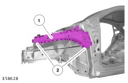
| Description and Operation Various symbols, signs, instructions and illustrations are used in this literature. Warnings and cautions have different meanings and require different ways of proceeding. Diagrammatic representations are provided with instructional signs for improved clarity. When reading this handbook, you will come across the points WARNING, CAUTION AND NOTE. These points are always immediately before a single job step or a series of job steps. These are briefly explained below: WARNING:This caption is used when failure to follow instructions exactly or failure to follow them at all may result in a hazard to persons or in persons being injured. CAUTION:This caption is used when incorrectly following the test procedures or instructions or failure to follow them at all could lead to damage to the vehicle or components. NOTE:This heading is used when the technician should be made aware of special or extra information. Item numbers Item numbers are inserted into a diagram when details need to be emphasized. Item numbers with one indicator line An item number and an indicator line point to a special location or a component. In this diagram a component and a row of spot welds are indicated. 1 - Apron panel reinforcement Item numbers with two indicator lines If two indicator lines lead away from one item number, then an area is being referred to. In this case the area with the spot welds to be separated is shown. Black arrows If the illustration of a detail is unambiguous, or there is only one detail shown, then no item number is used. A black arrow is used for this. Broken arrows Broken arrows represent movement. In this case the component must be removed in the direction given. Enlargement/detail If a detail cannot be clearly seen in the illustration because of its size or location, it is shown enlarged in a separate window. In this case a detail on the back of the B-pillar cannot be seen, and is therefore shown separately. Different colors or shading Different colors or shading are used to depict special areas. In an assembly operation, the colors show the sequence of removal steps. In the repair specifications, the first component or the first partial replacement component is always shown in magenta. The second component in an illustration is shown in turquoise and a third component is shown in dark green. Spot welds, weld seams and cut lines are shown in black. This principle also applies to line drawings. In these, illustrations under the same topic will always show the same colors for the same components. |