| Diagnosis and Testing Refer to Wiring Diagrams Section 501-16, for schematic and connector information. Special Tool(s) | | Terminal Probe Kit 29-011 A | Inspection and Checking - Verify the customer concern.
- Visually check for any obvious mechanical or electrical damage.
Visual inspection chart | Mechanical | Electrical | - Wiper blade(s)
- Wiper arm shaft
- Washer reservoir
- Hose(s)
- Nozzles
| - Fuse(s)
- Connectors
- Wiring harness.
- Washer pump
- Wiper motor(s)
| - Resolve any obvious causes or concerns found during the visual inspection before carrying out any further tests.
- If the concern persists, check the symptoms and continue with the symptom chart.
Symptom Chart Symptom Chart | Symptom | Possible Sources | Action | | Wipers inoperative | * Fuse * Circuit(s) * Wash/wipe switch * Wiper motor * Rear wiper motor * Central junction box (CJB) | * | | Wipers permanently switched on | * Circuit(s) * Wash/wipe switch * Wiper motor * Rear wiper motor | * | | Slow/fast wipe not working properly (intermittent mode OK) | * Circuit(s) * Wash/wipe switch * Wiper motor | * | | Intermittent wipe mode not working properly (fast/slow wipe OK) | * Circuit(s) * Wash/wipe switch * Intermittent wipe relay, front | * | | The wipers do not return to the park position after switching them off | * Circuit(s) * Wash/wipe switch * Wiper motor * Rear wiper motor * Intermittent wipe relay | * | | Washer pump motor inoperative | * Circuit(s) * Washer pump motor * Wash/wipe switch | * | System Check | PINPOINT TEST A : WIPERS INOPERATIVE | | TEST CONDITIONS | DETAILS/RESULTS/ACTIONS | | A1: CHECK FUSE F16 (CJB). | | | 1 Ignition switch in position 0. | | | 2 CHECK fuse F16 (CJB). | | | 3 Check fuse F16 (20 A). | | | Is the fuse OK.? Yes No RENEW fuse F16 (20 A) and check the operation of the system. If the fuse blows again, LOCATE and REPAIR the short to ground using the Wiring Diagrams. CHECK the operation of the system. | | A2: CHECK THE VOLTAGE AT FUSE F16 (CJB) | | | 1 Ignition switch in position 0. | | | 2 Connect fuse F16 (CJB). | | | 3 Ignition switch in position II. | | | 4 Measure the voltage between fuse F16 (20 A) and ground. | | | Does the meter display battery voltage? Yes No CHECK CJB and RENEW as necessary. CHECK the operation of the system. | | A3: CHECK THE VOLTAGE AT THE WASH/WIPE SWITCH | | | 1 Ignition switch in position 0. | | | 2 Disconnect wash/wipe switch C65b. | | | 3 Ignition switch in position II. | | | 4 Measure the voltage between the wash/wipe switch, connector C65b, pin 7, circuit 14-AK19 (VT/OG), wiring harness side and ground. | | | Does the meter display battery voltage? Yes No LOCATE and REPAIR the break in circuit 14-AK1 (VT/BU) or 14- AK19 (VT/OG) between fuse F16 (CJB) and the wash/wipe switch using the Wiring Diagrams. CHECK the operation of the system. | | A4: CHECK THE WASH/WIPE SWITCH | | | 1 Ignition switch in position 0. | | | 2 Check the wash/wipe switch according to the component test in the Wiring Diagrams. | | | Is the wash/wipe switch OK? Yes - Rear wiper inoperative, before 02/2001: GO to A7. - Rear wiper inoperative, from 02/2001: GO to A10. No RENEW the wash/wipe switch. CHECK the operation of the system. | | A5: CHECK THE VOLTAGE AT THE WIPER MOTOR | | | 1 Connect wash/wipe switch C65b. | | | 2 Disconnect front wiper motor C43. | | | 3 Ignition switch in position II. | | | 4 Switch the wipers on at SLOW SPEED. | | | 5 Measure the voltage between the front wiper motor, connector C43, pin 5, circuit 14S-AK10 (VT/BK), wiring harness side and ground. | | | Does the meter display battery voltage? Yes No LOCATE and REPAIR the break in circuit 14S-AK10 (VT/BK) between the wash/wipe switch and the wiper motor using the Wiring Diagrams. CHECK the operation of the system. | | A6: CHECK THE GROUND CONNECTION OF THE FRONT WIPER MOTOR | | | 1 Ignition switch in position 0. | | | 2 Measure the resistance between the front wiper motor, connector C43, pin 1, circuit 31-AK8 (BK), wiring harness side and ground. | | | Is less than 2 Ohm measured? Yes Check the wiper motor according to the component check at the end of this section and RENEW as necessary. CHECK the operation of the system. No LOCATE and REPAIR the break in circuit 31-AK8 (BK) between the wiper motor and ground G6 using the Wiring Diagrams. CHECK the operation of the system. | | A7: CHECK VOLTAGE AT TAILGATE CONTACT PLATE | | | 1 Connect wash/wipe switch C65b. | | | 2 Disconnect tailgate contact plate C312a / C312b. | | | 3 Ignition switch in position II. | | | 4 Switch on the REAR WIPERS. | | | 5 Measure the voltage between the tailgate contact plate, connector C312a, pin 3, circuit 32-AK28 (WH/RD), wiring harness side and ground. | | | Does the meter display battery voltage? Yes No LOCATE and REPAIR the break in circuit 32-AK28 (WH/RD) between the tailgate contact plate and the wash/wipe switch using the Wiring Diagrams. CHECK the operation of the system. | | A8: CHECK TAILGATE CONTACT PLATE | | | 1 Use a fused test cable (20 A) to bridge connector C312a, pin 3, circuit 32-AK28 (WH/RD) and connector C312b, circuit (WH/RD) at the tailgate contact plate. | | | 2 Ignition switch in position II. | | | 3 Switch on the REAR WIPERS. | | | Does the rear wiper motor run? Yes RENEW the tailgate contact plate. CHECK the operation of the system. No | | A9: CHECK THE VOLTAGE AT THE REAR WIPER MOTOR | NOTE:The fused test cable between connector C312a, pin 3, circuit 32-AK28 (WH/RD) and connector C312b, circuit (WH/RD) remains connected. | | | 1 Ignition switch in position 0. | | | 2 Disconnect Rear wiper motor C344. | | | 3 Ignition switch in position II. | | | 4 Switch on the REAR WIPERS. | | | 5 Measure the voltage between the rear wiper motor, connector C344, pin 2, circuit 32-AK28 (WH/RD), wiring harness side and ground. | | | Does the meter display battery voltage? Yes CHECK the ground connection of the rear wiper motor housing and REPAIR if necessary. CHECK the operation of the system. If the concern is still not resolved, CHECK the rear wiper motor according to the component check at the end of this section and RENEW as necessary. CHECK the operation of the system. No LOCATE and REPAIR the break in circuit 32-AK28 (WH/RD) between the tailgate contact plate and the rear wiper motor using the Wiring Diagrams. CHECK the operation of the system. | | A10: CHECK THE VOLTAGE AT THE REAR WIPER MOTOR | | | 1 Connect wash/wipe switch C65b. | | | 2 Disconnect Rear wiper motor C344. | | | 3 Ignition switch in position II. | | | 4 Switch on the REAR WIPERS. | | | 5 Measure the voltage between the rear wiper motor, connector C344, pin 2, circuit 32-AK28 (WH/RD), wiring harness side and ground. | | | Does the meter display battery voltage? Yes CHECK the ground connection of the rear wiper motor housing and REPAIR if necessary. CHECK the operation of the system. If the concern is still not resolved, CHECK the rear wiper motor according to the component check at the end of this section and RENEW as necessary. CHECK the operation of the system. No LOCATE and REPAIR the break in circuit 32-AK28 (WH/RD) between the rear wiper motor, connector C344, pin 2 and the wash/wipe switch using the Wiring Diagrams. CHECK the operation of the system. | | PINPOINT TEST B : WIPERS PERMANENTLY SWITCHED ON | | TEST CONDITIONS | DETAILS/RESULTS/ACTIONS | | B1: DETERMINE THE CONDITIONS UNDER WHICH THE FAULT OCCURS | | | 1 Ignition switch in position 0. | | | 2 Disconnect wash/wipe switch C65b. | | | 3 Ignition switch in position II. | | | Does one of the wiper motors run? Yes - Front wiper is permanently switched on: GO to B2. - Rear wiper is permanently on, up to 02/2001 GO to B4. - Rear wiper is permanently on, from 02/2001 GO to B6. No CHECK the wash/wipe switch according to the component check in the Wiring Diagrams and RENEW as necessary. CHECK the operation of the system. | | B2: NARROW DOWN THE FAULT CONDITIONS - CHECK CIRCUIT 14S-AK10 (VT/BK) FOR SHORT TO BATTERY VOLTAGE | NOTE:Connector C65b, wash/wipe switch remains disconnected. | | | 1 Ignition switch in position 0. | | | 2 Disconnect front wiper motor C43. | | | 3 Ignition switch in position II. | | | 4 Measure the voltage between the wash/wipe switch, connector C65b, pin 3, circuit 14-AK10 (VT/BK), wiring harness side and ground. | | | Does the meter display battery voltage? Yes LOCATE and REPAIR the short to battery voltage in circuit 14S-AK10 (VT/BK) between the wash/wipe switch and the wiper motor using the Wiring Diagrams. CHECK the operation of the system. No | | B3: CHECK CIRCUIT 14S-AK11 (VT/OG) FOR SHORT TO BATTERY VOLTAGE | | | 1 Measure the voltage between the wash/wipe switch, connector C65b, pin 5, circuit 14-AK11 (VT/OG), wiring harness side and ground. | | | Does the meter display battery voltage? Yes LOCATE and REPAIR the short to battery voltage in circuit 14S-AK11 (VT/OG) between the wash/wipe switch and the wiper motor using the Wiring Diagrams. CHECK the operation of the system. No CHECK the front wiper motor according to the component check at the end of this section and RENEW as necessary. CHECK the operation of the system. | | B4: NARROW DOWN THE FAULT CONDITIONS - CHECK CIRCUIT 32-AK28 (WH/RD) FOR SHORT TO BATTERY VOLTAGE AT THE TAILGATE CONTACT PLATE | NOTE:Connector C65b, wash/wipe switch remains disconnected. | | | 1 Ignition switch in position II. | | | 2 Open the tailgate. Measure the voltage between the tailgate contact plate, connector C312a, pin 3, circuit 32-AK28 (WH/RD), and ground. | | | Does the meter display battery voltage? Yes LOCATE and REPAIR the short to battery voltage in circuit 32-AK28 (WH/RD) between the wash/wipe switch and the tailgate contact plate, connector C312a using the Wiring Diagrams. CHECK the operation of the system. No | | B5: CHECK THE VOLTAGE AT THE REAR WIPER MOTOR | | | 1 Disconnect Rear wiper motor C344. | | | 2 Ignition switch in position II. | | | 3 Measure the voltage between the rear wiper motor, connector C344, pin 2, circuit 32-AK28 (WH/RD), wiring harness side and ground. | | | Does the meter display battery voltage? Yes LOCATE and REPAIR the short to battery voltage in circuit 32-AK28 (WH/RD) between the rear wiper motor and the tailgate contact plate, connector C312b using the Wiring Diagrams. CHECK the operation of the system. No CHECK the rear wiper motor according to the component check at the end of this section and RENEW as necessary. CHECK the operation of the system. | | B6: CHECK CIRCUIT 32-AK28 (WH/RD) FOR SHORT TO BATTERY VOLTAGE | NOTE:Connector C65b, wash/wipe switch remains disconnected. | | | 1 Disconnect Rear wiper motor C344. | | | 2 Ignition switch in position II. | | | 3 Measure the voltage between the rear wiper motor, connector C344, pin 2, circuit 32-AK28 (WH/RD), wiring harness side and ground. | | | Does the meter display battery voltage? Yes LOCATE and REPAIR the short to battery voltage in circuit 32-AK28 (WH/RD) between the rear wiper motor and the wash/wipe switch using the Wiring Diagrams. CHECK the operation of the system. No CHECK the rear wiper motor according to the component check at the end of this section and RENEW as necessary. CHECK the operation of the system. | | PINPOINT TEST C : SLOW/FAST WIPE NOT WORKING PROPERLY (INTERMITTENT MODE OK) | | TEST CONDITIONS | DETAILS/RESULTS/ACTIONS | | C1: DETERMINE THE CONDITIONS UNDER WHICH THE FAULT OCCURS | | | 1 Ignition switch in position II. | | | 2 Switch on the SLOW and FAST WIPE modes in turn. | | | 3 Check the wipers. | | | Do the wipers operate at fast speed? Yes Slow wipe speed inoperative: CHECK the wash/wipe switch according to the component check in the Wiring Diagrams and RENEW as necessary. CHECK the operation of the system. No | | C2: CHECK THE VOLTAGE AT THE WIPER MOTOR | | | 1 Ignition switch in position 0. | | | 2 Disconnect front wiper motor C43. | | | 3 Ignition switch in position II. | | | 4 Switch on the wipers at FAST SPEED. | | | 5 Measure the voltage between the front wiper motor, connector C43, pin 4, circuit 14S-AK11 (VT/OG), wiring harness side and ground. | | | Does the meter display battery voltage? Yes RENEW the front wiper motor CHECK the operation of the system. No | | C3: CHECK THE WASH/WIPE SWITCH | | | 1 Ignition switch in position 0. | | | 2 Disconnect wash/wipe switch C65b. | | | 3 Check the wash/wipe switch according to the component test in the Wiring Diagrams. | | | Is the wash/wipe switch OK? Yes LOCATE and REPAIR the break in circuit 14S-AK11 (VT/OG) between the wash/wipe switch and the wiper motor using the Wiring Diagrams. CHECK the operation of the system. No RENEW the wash/wipe switch. CHECK the operation of the system. | | PINPOINT TEST D : INTERMITTENT WIPE MODE NOT WORKING PROPERLY (FAST/SLOW WIPE OK) | | TEST CONDITIONS | DETAILS/RESULTS/ACTIONS | | D1: DETERMINE THE CAUSE OF THE FAULT | | | 1 Ignition switch in position II. | | | 2 Switch SLOW WIPE on/off. | | | Does the front wiper return to the park position? Yes No | | D2: CHECK THE WASH/WIPE SWITCH | | | 1 Ignition switch in position 0. | | | 2 Disconnect wash/wipe switch C65b. | | | 3 Check the wash/wipe switch according to the component test in the Wiring Diagrams. | | | Is the wash/wipe switch OK? Yes No RENEW the wash/wipe switch. CHECK the operation of the system. | | D3: NARROW DOWN THE CONDITIONS UNDER WHICH THE FAULT OCCURS | | | 1 Disconnect front intermittent wipe relay C57. | | | 2 Measure the resistance between the wash/wipe switch, connector C65b, pin 9, circuit 31S-AK19 (BK/RD), wiring harness side and intermittent wipe relay, connector C57, pin 3. | | | Is less than 2 Ohm measured? Yes No LOCATE and REPAIR the break in circuit 31S-AK19 (BK/RD) between the wash/wipe switch C65b connector, pin 9, and the intermittent wipe relay using the Wiring Diagrams. CHECK the operation of the system. | | D4: MEASURE VOLTAGE AT INTERMITTENT WIPE RELAY AND WASH/WIPE SWITCH (CIRCUIT 14S-AK14 VT/BK) | | | 1 Connect wash/wipe switch C65b. | | | 2 Ignition switch in position II. | | | 3 Switch on the INTERMITTENT WIPE. | | | 4 Measure the voltage between the intermittent wipe rely, connector C57, pin 5, circuit 14S-AK14 (VT/BK), wiring harness side and ground. | | | Does the meter display battery voltage? Yes No LOCATE and REPAIR the break in circuit 14S-AK14 (VT/BK) between the intermittent wipe relay and the wash/wipe switch using the Wiring Diagrams. CHECK the operation of the system. | | D5: CHECK THE GROUND CONNECTION OF THE INTERMITTENT WIPE RELAY | | | 1 Measure the resistance between the intermittent wipe relay, connector C57, pin 2, circuit 31-AK14 (BK), wiring harness side and ground. | | | Is less than 2 Ohm measured? Yes RENEW the intermittent wipe relay. CHECK the operation of the system. No LOCATE and REPAIR the break in circuit 31-AK14 (BK) between the intermittent wipe relay and ground G6 using the Wiring Diagrams. CHECK the operation of the system. | | PINPOINT TEST E : THE WIPERS DO NOT RETURN TO THE PARK POSITION AFTER SWITCHING THEM OFF | | TEST CONDITIONS | DETAILS/RESULTS/ACTIONS | | E1: DETERMINE THE CAUSE OF THE FAULT | | | 1 Determine the cause of the fault. | | | Is the windscreen wiper parking function defective? Yes No - Rear wiper not returning to the initial position, before 02/2001: GO to E6. - Rear wiper not returning to the initial position, from 02/2001: GO to A9. | | E2: CHECK THE WASH/WIPE SWITCH | | | 1 Ignition switch in position 0. | | | 2 Disconnect wash/wipe switch C65b. | | | 3 Check the wash/wipe switch according to the component test in the Wiring Diagrams. | | | Is the wash/wipe switch OK? Yes No RENEW the wash/wipe switch. CHECK the operation of the system. | | E3: MEASURE VOLTAGE AT THE FRONT WIPER MOTOR (CIRCUIT 14-AK8 VT/BU) | | | 1 Disconnect front wiper motor C43. | | | 2 Ignition switch in position II. | | | 3 Measure the voltage between the front wiper motor, connector C43, pin 3, circuit 14-AK8 (VT/BU), wiring harness side and ground. | | | Does the meter display battery voltage? Yes No LOCATE and RECTIFY the break in circuit 14-AK8 (VT/BU) between the front wiper motor, connector C43, pin 3 and soldered connection S22 using the Wiring Diagrams. CHECK the operation of the system. | | E4: CHECK CIRCUIT 31S-AK9 (BK/OG) | | | 1 Measure the resistance between the front wiper motor, connector C43, pin 2, circuit 31S-AK9 (BK/OG), wiring harness side and intermittent wipe relay connector C57, pin 1. | | | Is less than 2 Ohm measured? Yes No LOCATE and RECTIFY the break in circuit 31-AK9 (BK/OG) between the front wiper motor, connector C43, pin 2 and the intermittent wipe relay using the Wiring Diagrams. CHECK the operation of the system. | | E5: CHECK CIRCUIT 31S-AK15 (BK/RD) | | | 1 Measure the resistance between the wash/wipe switch, connector C65b, pin 2, circuit 31S-AK15 (BK/RD), wiring harness side and intermittent wipe relay, connector C57, pin 1. | | | Is less than 2 Ohm measured? Yes CHECK the front wiper motor according to the component check at the end of this section and RENEW as necessary. CHECK the operation of the system. No LOCATE and RECTIFY the break in circuit 31S-AK15 (BK/RD) between the wash/wipe switch, connector C65b, pin 2, and the intermittent wipe relay using the Wiring Diagrams. CHECK the operation of the system. | | E6: CHECK VOLTAGE AT TAILGATE CONTACT PLATE | | | 1 Connect wash/wipe switch C65b. | | | 2 Disconnect tailgate contact plate C312a / C312b. | | | 3 Ignition switch in position II. | | | 4 Measure the voltage between the tailgate contact plate, connector C312a, pin 2, circuit 14-AK28 (VT/BU), wiring harness side and ground. | | | Does the meter display battery voltage? Yes No LOCATE and REPAIR the break in circuit 32-AK28 (WH/RD) between the tailgate contact plate and the wash/wipe switch using the Wiring Diagrams. CHECK the operation of the system. | | E7: CHECK TAILGATE CONTACT PLATE | | | 1 Ignition switch in position 0. | | | 2 Use a fused test cable (20 A) to bridge connector C312a and connector C312b, pin 2, circuit 14-AK28 (WH/RD) at the tailgate contact plate. | | | 3 Ignition switch in position II. | | | Does the rear wiper motor return to the park position? Yes RENEW the tailgate contact plate. CHECK the operation of the system. No | | E8: CHECK THE VOLTAGE AT THE REAR WIPER MOTOR (CIRCUIT 14-AK28 VT/BU) | NOTE:The fused test cable between connector C312a and connector C312b, pin 2, circuit 14-AK28 (VT/BU) remains connected. | | | 1 Ignition switch in position 0. | | | 2 Disconnect Rear wiper motor C344. | | | 3 Ignition switch in position II. | | | 4 Measure the voltage between the rear wiper motor, connector C344, pin 1, circuit 14-AK28 (VT/BU), wiring harness side and ground. | | | Does the meter display battery voltage? Yes CHECK the ground connection of the rear wiper motor housing and REPAIR if necessary. CHECK the operation of the system. If the concern is still not resolved, CHECK the rear wiper motor according to the component check at the end of this section and RENEW as necessary. CHECK the operation of the system. No LOCATE and RECTIFY the break in circuit 14-AK28 (VT/BU) between the tailgate contact plate and the rear wiper motor using the Wiring Diagrams. CHECK the operation of the system. | | E9: CHECK THE VOLTAGE AT THE REAR WIPER MOTOR (CIRCUIT 14-AK28 VT/BU) | | | 1 Ignition switch in position 0. | | | 2 Disconnect Rear wiper motor C344. | | | 3 Ignition switch in position II. | | | 4 Measure the voltage between the rear wiper motor, connector C344, pin 1, circuit 14-AK28 (VT/BU), wiring harness side and ground. | | | Does the meter display battery voltage? Yes CHECK the ground connection of the rear wiper motor housing and REPAIR if necessary. CHECK the operation of the system. If the concern is still not resolved, CHECK the rear wiper motor according to the component check at the end of this section and RENEW as necessary. CHECK the operation of the system. No LOCATE and RECTIFY the break in circuit 14-AK28 (VT/BU) between soldered connection, S22 and the rear wiper motor using the Wiring Diagrams. CHECK the operation of the system. | | PINPOINT TEST F : WASHER PUMP MOTOR INOPERATIVE | | TEST CONDITIONS | DETAILS/RESULTS/ACTIONS | | F1: DETERMINE THE CAUSE OF THE FAULT | | | 1 Determine the cause of the fault. | | | Is the washer function inoperative at the front and rear? Yes No Only washer function at rear or wash/wipe function at front: RENEW the wash/wipe switch. CHECK the operation of the system. | | F2: CHECK THE WASH/WIPE SWITCH | | | 1 Ignition switch in position 0. | | | 2 Disconnect wash/wipe switch C65b. | | | 3 Check the wash/wipe switch according to the component test in the Wiring Diagrams. | | | Is the wash/wipe switch OK? Yes No RENEW the wash/wipe switch. CHECK the operation of the system. | | F3: CHECK GROUND CONNECTION AT WASH/WIPE SWITCH (CIRCUIT 31-LE29 BK) | | | 1 Measure the resistance between the wash/wipe switch, connector C65a, pin 8, circuit 31-LE29 (BK), wiring harness side and ground. | | | Is less than 2 Ohm measured? Yes No LOCATE and RECTIFY the break in circuit 31-LE29 (BK) between the wash/wipe switch and ground G6 using the Wiring Diagrams. CHECK the operation of the system. | | F4: CHECK THE VOLTAGE AT THE WASHER PUMP MOTOR | NOTE:Wash/wipe switch in the OFF position. | | | 1 Connect wash/wipe switch C65b. | | | 2 Disconnect washer pump motor, front/rear, C121. | | | 3 Ignition switch in position II. | | | 4 Measure the voltage between the washer pump motor, connector C121, pin 1, circuit 32-AK34 (WH/BK), wiring harness side and ground. | | | Does the meter display battery voltage? Yes No LOCATE and RECTIFY the break in circuit 32-AK34 (WH/BK) between the wash/wipe switch and the washer pump motor using the Wiring Diagrams. CHECK the operation of the system. | | F5: CHECK THE VOLTAGE AT THE WASHER PUMP MOTOR | | | 1 Measure the voltage between the washer pump motor, connector C121, pin 2, circuit 33-AK34 (YE/BK), wiring harness side and ground. | | | Does the meter display battery voltage? Yes RENEW the washer pump motor. CHECK the operation of the system. No LOCATE and RECTIFY the break in circuit 33-AK34 (YE/BK) between the wash/wipe switch and the washer pump motor using of the Wiring Diagrams. CHECK the operation of the system. | Component test: Front wiper motor. - Switch off the ignition.
- Disconnect the connector.
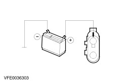
- Connect the test cables as described below:
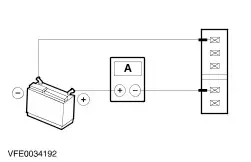
- Connect an external 12 V DC supply for a minimum current of 10 A (alternatively use a fused auxiliary cable) to the vehicle battery.
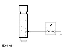
- Check the wiper motor in the SLOW WIPE setting.
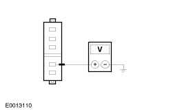
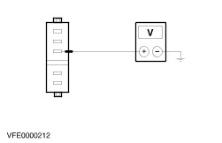
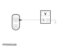
- Connect the positive terminal of the power supply to the positive terminal of the digital multimeter.
- Connect the negative terminal of the power supply to the wiper motor, pin 1, or to the housing of the wiper motor.
- Connect the negative terminal of the digital multimeter to the wiper motor, pin 5. The wiper motor runs at slow speed.
Measure the current. Is the reading on the digital multimeter approx. 1.5 A? If yes, GO TO 2. If not, RENEW the wiper motor. - Check the wiper motor in the FAST WIPE setting.
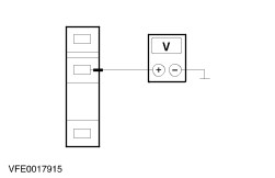
- Connect the positive terminal of the power supply to the positive terminal of the digital multimeter.
- Connect the negative terminal of the power supply to the wiper motor, pin 1, or to the housing of the wiper motor.
- Connect the negative terminal of the digital multimeter to the wiper motor, pin 4. The wiper motor runs at fast speed.
Measure the current. Is the reading on the digital multimeter approx. 2.2 A? If yes, GO TO 3. If not, RENEW the wiper motor. - Check the wiper motor in the PARK POSITION
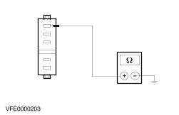
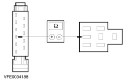
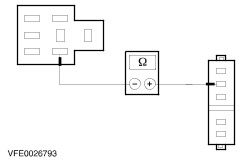
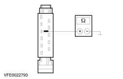
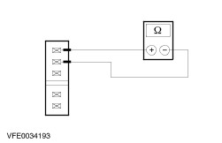
Measure the resistance at the front wiper motor between pin 2 and pin 1 (or the housing of the wiper motor). Is the resistance less than 2 Ohm? If yes, GO TO 4. If not, GO TO 3 and REPEAT this test step. (If not again, RENEW the wiper motor.) - Check the park position of the wiper motor
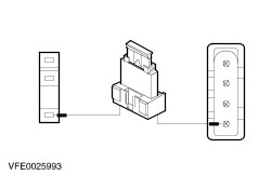
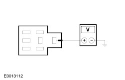
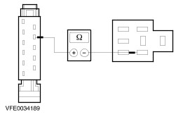
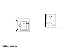
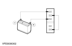
NOTE:The wiper motor is not in the park position. - Connect the positive terminal of the power supply to the wiper motor, pin 3.
- Connect the negative terminal of the power supply to the wiper motor, pin 1.
- Connect a jumper wire to the wiper motor between pin 5 and pin 2, the motor must return to the PARK POSITION.
Check the position Does the wiper motor return to the PARK POSITION? If yes then the wiper motor is OK. If not, GO TO 4 and REPEAT this test step. (If not again, RENEW the wiper motor.) Rear wiper motor - Switch off the ignition.
- Disconnect the connector.
- Connect the test cables as described below:
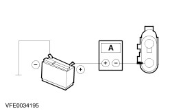
- Connect an external 12 V DC supply for a minimum current of 10 A (alternatively use a fused auxiliary cable) to the vehicle battery.
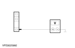
- Check operation of the wiper motor.
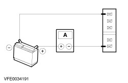
- Connect the positive terminal of the power supply to the positive terminal of the digital multimeter.
- Connect the negative terminal of the voltage supply to ground or to the wiper motor housing.
- Connect the negative terminal of the digital multimeter to the wiper motor, pin 2. Does the wiper motor run?
Measure the current. Is the reading on the digital multimeter approx. 1.5 A? If yes, GO TO 6. If not, RENEW the wiper motor. - Check the park position of the wiper motor
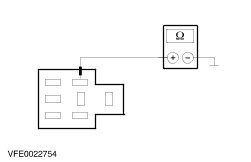
NOTE:The wiper motor is not in the park position. - Connect the positive terminal of the power supply to the wiper motor, pin 1.
- Connect the negative terminal of the voltage supply to ground or to the wiper motor housing.
- The motor must return to the PARK POSITION.
Check the position Does the wiper motor return to the PARK POSITION? If yes then the wiper motor is OK. If not, GO TO 6 and REPEAT this test step. (If not again, RENEW the wiper motor.) |