Refer to Wiring Diagrams Section 501-20B, for schematic and connector information.
General Equipment
Worldwide diagnostic system (WDS)
Diagnosing Customer Concerns Without Hard DTCs/LFCs
WARNING:The battery back up power supply must be depleted before any work is carried out on the supplemental restraint system. Wait at least 15 minutes after disconnecting the battery ground cable before disconnecting any supplemental restraint system electrical connector. Failure to follow this instruction may result in personal injury.
NOTE:Following the pinpoint tests when a lamp fault code (LFC) is not present, will result in needless replacement of air bag system components and repeat repairs.
Speak with the customer to determine if a particular set of conditions must be met in order to indicate a fault. If a LFC is reported by the customer but is not present when the vehicle comes in for repair, pinpoint test diagnostics cannot be used. Instruct the customer on how to count a LFC.
Diagnosing Customer Concerns with Hard DTCs/LFCs
WARNING:Do not use substitute air bag simulators when working on the supplemental restraint system. Use only the appropriate tool. Failure to follow these instructions may result in personal injury.
Most air bag system diagnostic procedures require the use of system deactivation and system reactivation procedures. These procedures require the air bag module(s) to be disconnected from the SRS, thereby removing the risk of the air bag deployment while diagnostics are carried out.
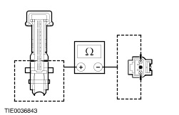
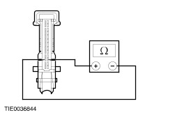
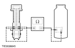
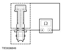
Air bag simulators are required to carry out diagnosis and testing of the air bag system. The simulator contains a resistor, used to simulate an air bag module connection to the system. It is not acceptable to short-circuit the air bag module connections with a 0 ohm jumper wire. If a 0 ohm jumper wire is used to short-circuit the air bag module connections, a LFC will be displayed.
Deactivation
WARNING:The battery back up power supply must be depleted before any work is carried out on the supplemental restraint system. Wait at least 15 minutes after disconnecting the battery ground cable before disconnecting any supplemental restraint system electrical connector. Failure to follow this instruction may result in personal injury.
- Disconnect the battery ground cable.
REFER to: Battery Disconnect and Connect (414-01 Battery, Mounting and Cables, General Procedures).
- Wait at least 15 minutes for the backup power supply in the air bag control module to deplete its stored energy.
WARNING:To minimize the possibility of premature deployment, live air bag modules must only be placed on a work benches which have been ground bonded and with the trim cover facing up. Failure to follow this instruction may result in personal injury.
- Remove the driver air bag module from the vehicle.
REFER to: Driver Air Bag Module (501-20B Supplemental Restraint System, Removal and Installation).
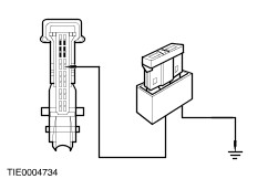
- Connect the driver air bag simulator to the sub-harness in place of the driver air bag module at the top of the steering column.
- Disconnect the passenger air bag module electrical connector (if equipped).
REFER to: Passenger Air Bag Module (501-20B Supplemental Restraint System, Removal and Installation).
- Connect the passenger air bag simulator to the harness in place of the passenger air bag module.
- Connect the battery ground cable.
REFER to: Battery Disconnect and Connect (414-01 Battery, Mounting and Cables, General Procedures).
Reactivation
WARNING:The air bag simulators must be removed and the air bag module(s) reconnected when reactivated to avoid non-deployment in a collision. Failure to follow this instruction may result in personal injury.
- Disconnect the battery ground cable.
REFER to: Battery Disconnect and Connect (414-01 Battery, Mounting and Cables, General Procedures).
- Wait at least 15 minutes for the backup power supply in the air bag control module to deplete its stored energy.
- Remove the driver air bag simulator from the sub-harness at the top of the steering column.
- Connect and install the driver air bag module.
REFER to: Driver Air Bag Module (501-20B Supplemental Restraint System, Removal and Installation).
- Remove the passenger air bag simulator from the passenger air bag module harness.
- Connect the passenger air bag module electrical connector (if equipped).
REFER to: Passenger Air Bag Module (501-20B Supplemental Restraint System, Removal and Installation).
- Connect the battery ground cable.
REFER to: Battery Disconnect and Connect (414-01 Battery, Mounting and Cables, General Procedures).
Glossary
Air Bag Simulator
Air bag simulators are used to simulate air bag module connections to the system.
Deactivate The System
Deactivate the system means to carry out the deactivation procedure. REFER to Deactivation in this procedure.
Prove Out The System
The air bag warning indicator will illuminate for approximately three seconds at key ON. If there is a fault condition, after a two second delay, the air bag warning indicator will:
- illuminate continuously
- flash
Reactivate The System
Reactivate the system means to carry out the reactivation procedure. REFER to Reactivation in this procedure.
Principles of Operation
Supplemental Restraint System (SRS) Operation
The supplemental restraint system is DC fired.
In the event of a severe frontal or three-quarter frontal impact, in excess of a predetermined limit, the driver and passenger (if equipped) front air bag(s) will deploy.
Air bag deployment will only occur, in the event of a severe collision when the ignition key is in the RUN position.
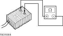
Air Bag Control Module
The air bag control module is mounted horizontally to the crossmember beneath the floor console, to facilitate impact sensing along the longitudinal axis. The air bag control module retains full control of the whole system, providing continual system checks and full diagnostic capabilities. A visual warning indicator that is housed within the instrument cluster, is illuminated when the ignition is switched ON for approximately three seconds then goes out. If a fault occurs the warning indicator, depending on the nature of the fault, begins to flash or illuminates continuously after five seconds.
In the event of a failure in the vehicle power supply during or after an accident, the air bag control module provides an auxiliary power supply, sufficient to deploy the air bag(s) for a minimum of 150ms. The back up power supply is discharged by the air bag control module within 15 minutes of the battery ground cable being disconnected. Thus making sure the supplemental restraint system remains operational.
The air bag control module contains a micro-controller to evaluate and process impact data and two micromachine sensors. An electronic accelerometer that converts the actual acceleration and deceleration force along the vehicles longitudinal axis into electrical signals. When both these sensors sense an impact, in excess of a predetermined limit, the air bag control module initiates the circuit to deploy the frontal air bags. The two micromachine sensors prevent unintentional deployment of the frontal air bags.
Air Bag Warning Indicator
The air bag warning indicator is incorporated into the instrument cluster, together with the automatic detach detect (ADD) circuit. The air bag warning indicator illuminates for three seconds at key ON. If the system self-tests OK the indicator extinguishes, if a fault is detected the indicator will flash after five seconds, illuminate continually from key ON or not illuminate at all, depending on the nature of the fault.
The ADD circuit is designed to illuminate the air bag warning indicator continuously, if the air bag control module circuit is broken, either by loss of power or ground supply. The air bag control module retaining bolts are part of the ground circuit.
Inspection and Verification
- Verify the customer concern.
- Visually inspect for obvious signs of mechanical or electrical damage.
Visual Inspection Chart