| Removal and Installation Special Tool(s) | | Guide pins, subframe 15-097A | Removal All Vehicles | | -
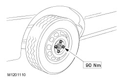
Slacken the wheel nuts, raise the vehicle and remove the rear road wheels. | | | -
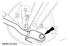
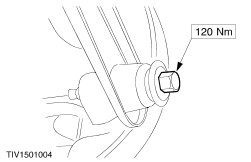
Detach the tie bars from the knuckle assemblies (one bolt each side). | | | -
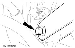
Detach the stabilizer bar links from the front lateral arms (one nut each side). | Vehicles with Anti-lock brakes | | -
Remove the ABS sensors (one each side). | All vehicles | | -
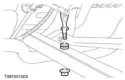
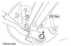
Detach the front lateral arms from the knuckle assemblies (one nut and bolt each side). | | | -
Detach the rear lateral arms from the knuckle assemblies (one nut and bolt each side). | | | -
Detach the suspension units from the crossmember ledges (one each side). - Raise the suspension units on a jack.
- Detach the suspension units from the crossmember ledges.
| | | -
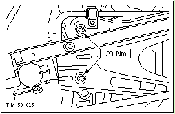
Remove the crossmember (two bolts each side). | | | -
Remove the stabilizer bar (one bolt each side). | | | -
Remove the front and rear lateral arms. - Remove the front lateral arm from the crossmember (one nut and bolt each side).
- Remove the rear lateral arm from the crossmember (one nut, excentric washer and cam bolt each side).
| Installation All Vehicles | | -
NOTE:The final torquing of the rear suspension components should be carried out with the vehicle on its wheels. Install the components in reverse order. | | | -
Align the crossmember. - Install the guide pins into the alignment holes.
- Slide the locking plates into the locking grooves and tighten the locking sleeve.
| Vehicles with Anti-lock brakes All vehicles | | -
Check the toe setting and adjust if necessary. Refer to General Procedures. | |