| General Procedures Special Tool(s) | | Compressor, valve clearance adjustment 303-563A (21218) | | | Pliers, spark plug connector 303-622 (21226) | General Equipment Feeler gauges External micrometer Sleeve (8 x 12 mm) or suitable washers Materials Name Specification Cable ties Silicone grease for spark plug connector seal A960-M1C171-AA Adjust | | -
CAUTION:To correct the valve clearances the adjusting shims must be changed. Standard preparatory measures - Make a note of the radio keycode.
- Make a note of the preset radio stations.
| | | -
CAUTION:Disconnect the battery ground cable. NOTE:Do not remove the upper timing belt cover. Unscrew the bolts on the upper timing belt cover. | | | -
NOTE:This step only applies to vehicles which are liquid propane gas (LPG) operated. Detach the LPG fuel distribution pipe.
For additional information, refer to: Fuel Injection Supply Manifold (303-04E Fuel Charging and Controls - Liquified Petroleum Gas (LPG), Removal and Installation).
| | | -
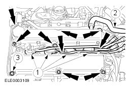
CAUTION:Do not pull on the cable when pulling off the spark plug connector. If necessary disconnect the connector from the ignition coil to prevent kinking of the cable. Turn the spark plug connector slightly before pulling it off in order to loosen the seal. CAUTION:Pull off the spark plug connector in a straight movement. NOTE:Loosening sequence: from the outside inwards, working diagonally. Remove the cylinder head cover. - Pull off the spark plug connector.
- Detach the PCV hose.
- Remove the ten bolts.
| | | -
CAUTION:Only turn the engine by the crankshaft and in the normal direction of rotation. Set the engine to ignition point on cylinder no. 1 (TDC). | | | -
NOTE:Make a note of the measured valve clearances, sorted by cylinder and valve. - Permissible valve clearance: Intake (0,11 - 0,18 mm)
- Permissible valve clearance: Exhaust (0,27 - 0,34 mm)
| | | -
CAUTION:Only turn the engine by the crankshaft. Measure the valve clearance (continued). - Rotate the engine by the crankshaft in the normal direction of rotation through another 180 degrees. The sequence of the measurements is by the firing order: 1-3-4-2.
- Repeat the previous steps on all other cylinders.
| | | -
NOTE:Only carry out the following steps if the valves need adjusting. | | | -
NOTE:Aim for a mid-range clearance value (intake 0,15 mm; exhaust 0,30 mm). NOTE:The number on the adjustment shim corresponds to the thickness of the shim. Example: 222 = 2,22 mm Determining the required shim thickness. - Remove the adjustment shims from the valve tappets and read off each thickness from the back of the shim (measure them with an external micrometer if the thickness is no longer legible).
- Determine the required shim thickness and install the shim.
1. Intake valves: required shim thickness = thickness of installed shim + measured valve clearance - 0,15 mm. 2. Exhaust valves: required shim thickness = thickness of installed shim + measured valve clearance - 0,30 mm. | | | -
Recheck the valve clearance after installing new shims. | | | -
CAUTION:Use a blunt object (e.g. a plastic cable tie) to apply the silicone grease in order to avoid damaging the spark plug connector seal. CAUTION:Push on the spark plug connectors, keeping them in line with the spark plugs. NOTE:Apply silicone grease to the inside of the spark plug connector up to a depth of 5-10 mm. Install the cylinder head cover. - Coat the spark plug threads with Never Seeze.
- Install the spark plugs.
- Screw in the cylinder head cover bolts in two stages.
- Stage 2 (metal cylinder head cover): 7 Nm
- Stage 2 (plastic cylinder head cover): 9 Nm
- Push on the spark plug connector until it engages.
| | | -
NOTE:This step only applies to vehicles running on liquid propane gas (LPG). Attach the LPG fuel distribution pipe.
For additional information, refer to: Fuel Injection Supply Manifold (303-04E Fuel Charging and Controls - Liquified Petroleum Gas (LPG), Removal and Installation).
| | | -
NOTE:Check the seating of the timing belt upper cover gasket and correct it if necessary. Attach the timing belt upper cover. | | | -
Connect the battery ground cable. - Reprogram the preset radio stations.
- Carry out a road test to enable the PCM to collect data.
| | | -
Check fluid levels and correct if necessary. | | | -
Check the routing of vacuum hoses and cables, and secure them using cable ties . | | |