| PINPOINT TEST A : THE SPEED CONTROL IS INOPERATIVE |
| TEST CONDITIONS | DETAILS/RESULTS/ACTIONS |
| A1: CHECK HORN OPERATION |
| | 1 Press the horn switch(es). |
| | Does the horn sound? Yes No |
| A2: CHECK ON SWITCH OPERATION |
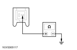
| | 1 Disconnect Speed Control Actuator C833. |
| | 2 Measure the voltage between the speed control actuator C833 pin 6, circuit 31-PG13 (BK), harness side and ground with the ON switch pressed. |
| | Is the voltage greater than 10 volts? Yes No INSTALL a new speed control switch(es). REFER to Speed Control Switch in this section. TEST the system for normal operation. |
| A3: CHECK SWITCH SIGNAL TO ACTUATOR |
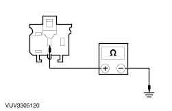
| | 1 Measure the resistance between the speed control actuator C833 pin 5, circuit 8-PG13 (WH), harness side and speed control actuator C833 pin 6, circuit 31-PG13 (BK), harness side while pressing the off switch. |
| | Is the resistance less than 5 ohms? Yes No |
| A4: CHECK CIRCUIT 8-PG13 |
WARNING:Refer to Section 501-20B for the correct airbag deactivation procedure. |
| | 1 Disconnect Air bag sliding contact C896. |
| | 2 Measure the resistance between the speed control actuator C833 pin 5, circuit 8-PG13 (WH), harness side and the air bag sliding contact C896 pin 3, circuit 8-PG13 (WH), harness side. |
| | Is the resistance less than 5 ohms? Yes No REPAIR the circuit. TEST the system for normal operation. |
| A5: CHECK CONTINUITY OF AIR BAG SLIDING CONTACT |
| | 1 Disconnect Speed Control Switch. |
| | 2 Check for correct continuity across the air bag sliding contact. |
| | Is the air bag sliding contact OK? Yes INSTALL a new speed control switch(es). REFER to Speed Control Switch in this section. TEST the system for normal operation. No |
| A6: CHECK CIRCUIT 91-PG12 |
| | 1 Measure the resistance between the speed control actuator C833 pin 10, circuit 91-PG12 (BK), harness side and ground. |
| | Is the resistance less than 5 ohms? Yes No REPAIR the circuit. TEST the system for normal operation. |
| A7: CHECK CIRCUIT 14-PG12 |
| | 1 Ignition switch in position II. |
| | 2 Measure the voltage between the speed control actuator C833 pin 7, circuit 14-PG12 (VT/WH), harness side and ground. |
| | Is the voltage greater than 10 volts? Yes No REPAIR the circuit. TEST the system for normal operation. |
| A8: CHECK BRAKE PEDAL POSITION (BPP) SWITCH SIGNAL TO MODULE |
| | 1 Measure the voltage between the speed control actuator C833 pin 9, circuit 14S-PG16 (14-PG16 for manual transmission) (VT/YE), harness side and ground. |
| | Is the voltage greater than 10 volts? Yes No |
| A9: CHECK BRAKE PEDAL POSITION (BPP) SWITCH |
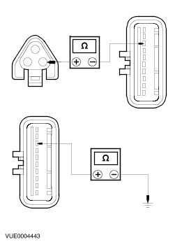
| | 1 Disconnect BPP Switch C824. |
| | 2 Measure the resistance between the BPP switch C824 pin 1 and pin 2, while pressing the switch plunger and also with the plunger released. |
| | Are the resistances greater than 10,000 ohms with the plunger pressed and less than 5 ohms with the plunger released? Yes No INSTALL a new BPP switch. TEST the system for normal operation. |
| A10: CHECK CIRCUIT 14-PG6 |
| | 1 Measure the voltage between the BPP switch C824 pin 1, circuit 14-PG6 (VT/YE), harness side and ground. |
| | Is the voltage greater than 10 volts? Yes No REPAIR the circuit. TEST the system for normal operation. |
| A11: CHECK CIRCUIT 14S-PG16 (14-PG16 FOR MANUAL TRANSMISSION) |
| | 1 Measure the resistance between the speed control actuator C833 pin 9, circuit 14S-PG16 (14-PG16 for manual transmission) (VT/YE), harness side and the BPP switch C824 pin 2, circuit 14S-PG16 (14-PG16 for manual transmission) (VT/YE), harness side. |
| | Is the resistance less than 5 ohms? Yes ADJUST the BPP switch. TEST the system for normal operation. No REPAIR the circuit in question. TEST the system for normal operation. |
| A12: CHECK STOPLAMP SWITCH SIGNAL TO ACTUATOR |
| | 1 Measure the voltage between the speed control actuator C833 pin 4, circuit 14S-PG17 (VT/BU), harness side and ground while pressing the brake pedal. |
| | Is the voltage greater than 10 volts? Yes No If the stoplamps operate correctly, GO to A13. . |
| A13: CHECK POWER TO SPEED CONTROL CUT-OFF RELAY |
| | 1 Disconnect Speed Control Cut-Off Relay C434. |
| | 2 Measure the voltage between the speed control cut-off relay C434, circuit 14S-PG15 (VT), harness side and ground while pressing the brake pedal. |
| | Is the voltage greater than 10 volts? Yes No If automatic transmission, REPAIR circuit(s) 14S-PG15/14S-PG17. TEST the system for normal operation |
| A14: CHECK POWER TO CLUTCH PEDAL POSITION (CPP) SWITCH |
| | 1 Disconnect CPP Switch C825. |
| | 2 Measure the voltage between the CPP switch C825 pin 3, circuit 14S-PG7 (VT/BU), harness side and ground while pressing the clutch pedal. |
| | Is the voltage greater than 10 volts? Yes No REPAIR circuit 14S-PG7. TEST the system for normal operation. |
| A15: CHECK THE CLUTCH PEDAL POSITION (CPP) SWITCH |
| | 1 Measure the resistance between the CPP switch pin 1 and pin 3, component side. |
| | Is the resistance less than 5 ohms? Yes REPAIR circuit(s) 14S-PG17/14S-PG15. TEST the system for normal operation. No |
| A16: CHECK SPEED CONTROL CUT-OFF RELAY SIGNAL TO ACTUATOR |
| | 1 Measure the resistance between the speed control cut-off relay C434, circuit 14S-PG17 (VT/BU), harness side and the speed control actuator C833 pin 4, circuit 14S-PG17 (VT/BU), harness side. |
| | Is the resistance less than 5 ohms? Yes INSTALL a new speed control cut-off relay. TEST the system for normal operation. No REPAIR circuit 14S-PG17. TEST the system for normal operation. |
| A17: CHECK VEHICLE SPEED SENSOR (VSS) SIGNAL TO ACTUATOR |
| | 1 Disconnect VSS C823. |
| | 2 Measure the resistance between the VSS C823 pin 2, circuit 8-PC60 (WH/BU), harness side and the speed control actuator C833 pin 3, circuit 8-PG18 (WH/BU), harness side. - Measure the resistance between the speed control actuator C833 pin 3, circuit 8-PG18 (WH/BU), harness side and ground.
|
| | Is the resistance less than 5 ohms between C823 and C833 and greater than 10,000 ohms between C833 and ground? Yes No REPAIR circuit 8-PG18. TEST the system for normal operation. |