| Diagnosis and Testing Refer to Wiring Diagrams Section 415-01, for schematic and connector information. Inspection and Verification - Verify the customer concern by operating the system.
- Visually inspect for obvious signs of mechanical or electrical damage.
Visual Inspection Chart | Mechanical | Electrical | - Audio unit
- Antenna
- Speaker(s)
| - Fuse 36 (15A)
- Loose or corroded connector(s)
- Wiring harness
- Audio unit
| - If an obvious cause for an observed or reported concern is found, correct the cause (if possible) before proceeding to the next step.
- If an obvious cause is not found, codes may be shown in the audio unit display. Check the audio unit display for the following Error Codes:
- for vehicles with 6000 audio unit refer to the CD Error Codes - vehicles with 6000 Audio Unit
- for vehicles with CD changer refer to the CD Error Codes - vehicles with CD Changer
- If no error codes are displayed on the audio unit refer to the Self-Diagnostic Mode.
CD Error Codes - vehicles with 6000 Audio Unit Error Codes | Error Code | Error Description | Error Rectification | | E11 | SPI Bus Failure | CHECK and REPAIR the wiring harness. If the wiring harness is OK, DISCONNECT the audio unit power connector, SWITCH the audio unit ON and OFF four times then CONNECT the audio unit power connector. TEST the system for normal operation. If the error code is still displayed, INSTALL a new audio unit.
REFER to: Audio Unit (415-01 Audio Unit, Removal and Installation).
TEST the system for normal operation. | | E12 | Communications Error | CHECK and REPAIR the wiring harness. If the wiring harness is OK, DISCONNECT the audio unit power connector, SWITCH the audio unit ON and OFF four times then CONNECT the audio unit power connector. TEST the system for normal operation. If the error code is still displayed, INSTALL a new audio unit.
REFER to: Audio Unit (415-01 Audio Unit, Removal and Installation).
TEST the system for normal operation. | | E14 | Overtemp Error | The Audio unit is too hot, unit will not work until it has cooled down. Check the heater duct(s) are not bleeding hot air on to the radio. If the concern persists, INSTALL a new audio unit.
REFER to: Audio Unit (415-01 Audio Unit, Removal and Installation).
TEST the system for normal operation. | | E15 | Mechanical Error | Install a new audio unit.
REFER to: Audio Unit (415-01 Audio Unit, Removal and Installation).
TEST the system for normal operation. | | E16 | CD Eject Failure | Install a new audio unit.
REFER to: Audio Unit (415-01 Audio Unit, Removal and Installation).
TEST the system for normal operation. | CD Error Codes - vehicles with CD Changer Error Codes | Error Code | Error Description | Error Rectification | | E2 | Communications Error | CHECK and REPAIR the CD changer harness. REFER to the Component Test in this section. If the CD changer harness is OK. INSTALL a new CD changer.
REFER to: Compact Disc (CD) Changer - Vehicles Without: Navigation System (415-01 Audio Unit, Removal and Installation).
TEST the system for normal operation. | | E3 | Focus Error | CD is upside down or dirty. Clean the CD and try it again, if the error code is still displayed, INSERT a different CD. If the error code is still displayed. INSTALL a new CD changer.
REFER to: Compact Disc (CD) Changer - Vehicles Without: Navigation System (415-01 Audio Unit, Removal and Installation).
TEST the system for normal operation. | | E4 | Overtemp Error | The CD changer is too hot, unit will not work until it has cooled down. Check the heater duct(s) are not bleeding hot air on to the CD changer. If the concern persists, INSTALL a new CD changer.
REFER to: Compact Disc (CD) Changer - Vehicles Without: Navigation System (415-01 Audio Unit, Removal and Installation).
TEST the system for normal operation. | | E5 | Mechanical Error | Install a new CD changer.
REFER to: Compact Disc (CD) Changer - Vehicles Without: Navigation System (415-01 Audio Unit, Removal and Installation).
TEST the system for normal operation. | Self-Diagnostic Mode - To enter the audio unit Self-Diagnostic Mode, switch the audio unit ON. Within four seconds depress the preset buttons 3 and 6 together.
- Release the preset buttons 3 and 6 and the audio unit will enter the Self-Diagnostic Mode.
- To navigate through the audio unit Self-Diagnostic Mode, depress the preset button 6.
- To exit the Self-Diagnostic Mode do not press any button on the audio unit for 10 seconds.
- If the Self-Diagnostic Mode cannot be accessed, use WDS to diagnose the audio unit.
Self-Diagnostic Mode | Test | Syntax Displayed | Circuit Tested | Description | | 1. FM waveband check. | FM frequency received. | Antenna signal. | Tests signal from the antenna cable. | | 2. Traffic Announcement. | TP | Traffic announcement volume level. | Allows adjustment of the volume. | | 3. Test speaker circuit left hand front speaker. | 4CH LF for four channel system 2CH LF for two channel system. | Left hand front speaker circuit. | Test speaker circuit. | | 4. Test speaker circuit right hand front speaker. | 4CH RF for four channel system 2CH RF for two channel system. | Right hand front speaker circuit. | Test speaker circuit. | | 5. Test speaker circuit left hand rear speaker. | 4CH LR for four channel system. | Left hand rear speaker circuit. | Test speaker circuit. | | 6. Test speaker circuit right hand rear speaker. | 4CH RR for four channel system. | Right hand rear speaker circuit. | Test speaker circuit. | | 7. Test communications with compact disc autochanger (if equipped). | CDDJ OK if communications are achieved and NO CDDJ if no communications are achieved. | Compact disc communications circuit. | Test compact disc circuit. | - If the concern remains after the Self-Diagnostic Mode, refer to the Symptom Chart.
Symptom Chart Symptom Chart | Symptom | Possible Sources | Action | | The audio unit is inoperative | * Fuse(s). * Circuit(s). * Audio unit. | * | | The display is blank -radio and cassette operates | * Audio unit. | * INSTALL a new audio unit.
REFER to: Audio Unit (415-01 Audio Unit, Removal and Installation).
TEST the system for normal operation. | | Poor reception | * Antenna. * Antenna cable. * Audio unit. | * | | Distorted sound from one or more speakers (Not All Speakers) | * Speaker(s). | * INSTALL new speaker(s).
REFER to: Front Door Speaker (415-03 Speakers, Removal and Installation).
TEST the system for normal operation. | | No sound from all of the speakers | * Speaker(s). * Circuit(s). * Audio unit. | * | | The CD player does not operate correctly | * Audio unit. | * Using a known good CD, verify the customer concern. If the concern persists INSTALL a new audio unit.
REFER to: Audio Unit (415-01 Audio Unit, Removal and Installation).
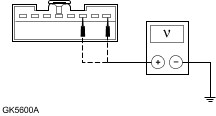
| | No sound from one or more of the speakers | * Circuit(s). * Audio unit. | * | | The CD changer is inoperative or does not operate correctly | * Fuse(s) * Circuit(s). * CD changer. | * | | The audio unit does not operate correctly | * Fuse 41 (20A). * Circuit(s). * Vehicle speed sensor (VSS). * Powertrain control module (PCM). * Audio unit. | * | | The audio unit remote control does not operate correctly | * Audio unit remote control. * Circuit(s). * Audio unit interface. * Audio unit. | * | CD Autochanger ERO Codes | Display Condition | Possible Causes | | Display blank | Connection. | | Error 02' | Connection. | | Error 03' | Focusing error. | | Error 04' | Thermal shutdown. | | Error 05' | Mechanical fault. | | Error 06' | Unable to read disc(s) | | Error 07' | Unable to read selected disc (displayed for 25 sec then select next disc). | | No CD' | Slot empty (CD autochanger display for 25 seconds then select next disc). | | NO DISCS | Magazine empty. | Pinpoint Tests | PINPOINT TEST A : THE AUDIO UNIT IS INOPERATIVE | | TEST CONDITIONS | DETAILS/RESULTS/ACTIONS | | A1: CHECK FOR VOLTAGE TO AUDIO UNIT | | | 1 Disconnect Audio Unit C443a. | | | 2 Ignition switch in position I. | | | 3 Measure the voltage between audio unit C443a pin 1, circuit 29-MD15 (OG/BK), harness side and ground; and between the audio unit C443a pin 3, circuit 75-MD15 (YE/GN), harness side and ground. | | | Are the voltages greater than 10 volts? Yes No | | A2: CHECK GROUND CIRCUITS 91-MD15 (BK/GN) AND 91-MD15A (BK/GN) FOR OPEN | | | 1 Measure the resistance between audio unit C443a pin 6, circuit 91-MD15 (BK/GN), harness side and ground; and between audio unit C443a pin 2, circuit 91-MD15A (BK/GN), harness side and ground. | | | Are the resistances less than 1 ohm? Yes INSTALL a new audio unit.
REFER to: Audio Unit (415-01 Audio Unit, Removal and Installation).
TEST the system for normal operation. No REPAIR the circuit in question. TEST the system for normal operation. | | A3: CHECK CIRCUIT 29-MD15 (OG/BK) FOR OPEN | | | 1 Ignition switch in position 0. | | | 2 Disconnect Fuse 36 (15A). | | | 3 Measure the resistance between central junction box (CJB) fuse 36 (15A) pin 2, and audio unit C443a pin 1, circuit 29-MD15 (OG/BK), harness side. | | | Is the resistance less than 1 ohm? Yes INSTALL a new audio unit.
REFER to: Audio Unit (415-01 Audio Unit, Removal and Installation).
TEST the system for normal operation. No REPAIR the circuit. TEST the system for normal operation. | | PINPOINT TEST B : POOR RECEPTION | | TEST CONDITIONS | DETAILS/RESULTS/ACTIONS | | B1: CHECK THE ANTENNA CABLE SHIELD | | | 1 Ignition switch in position 0. | | | 2 Disconnect the antenna cable from the audio unit. | | | 3 Measure the resistance between the antenna cable ground connector (shield), and ground. | | | Is the resistance less than 1 ohm? Yes No CLEAN and tighten the audio unit case ground and the antenna mast base connection to the body. If the concern persists, INSTALL a new antenna cable TEST the system for normal operation. | | B2: CHECK THE ANTENNA CENTER CONDUCTOR FOR OPEN | | | 1 Measure the resistance between the antenna center conductor and the antenna cable center conductor. | | | Is the resistance less than 1 ohm? Yes No CHECK in-line connectors. INSTALL a new antenna cable. TEST the system for normal operation. | | B3: CHECK ANTENNA CABLE FOR SHORT | | | 1 Measure the resistance between the antenna center conductor and the antenna ground (shield). | | | Is the resistance greater than 10,000 ohms (open circuit)? Yes CLEAN and TIGHTEN grounding points at the base of the antenna, audio unit case and battery negative cable to body. If the concern persists, INSTALL a new audio unit.
REFER to: Audio Unit (415-01 Audio Unit, Removal and Installation).
TEST the system for normal operation. No INSTALL a new antenna cable. TEST the system for normal operation. | | PINPOINT TEST C : NO SOUND FROM ALL OF THE SPEAKERS | | TEST CONDITIONS | DETAILS/RESULTS/ACTIONS | | C1: CHECK SPEAKER POSITIVE CIRCUIT FOR SHORT TO GROUND | | | 1 Ignition switch in position 0. | | | 2 Disconnect Audio Unit C443b. | | | 3 Measure the resistance between the following audio unit connectors, harness side and ground. - Measure the resistance between audio unit C443b pin 1, circuits 1-MD28 (WH) and 1-MD10 (WH/BK), harness side and ground.
- Measure the resistance between audio unit C443b pin 3, circuits 1-MD29 (WH/VT) and 1-MD11 (WH/VT), harness side and ground.
- Measure the resistance between audio unit C443b pin 5, circuits 1-MD28 (WH) and 1-MD17 (WH/RD), harness side and ground.
- Measure the resistance between audio unit C443b pin 7, circuits 1-MD29 (WH/VT) and 1-MD18 (WH), harness side and ground.
| | | Are the resistances greater than 10,000 ohms (open circuit)? Yes No REPAIR the circuit in question. TEST the system for normal operation. | | C2: CHECK SPEAKER RETURN CIRCUIT FOR SHORT TO GROUND | | | 1 Measure the resistance between the following audio unit connectors, harness side and ground. - Measure the resistance between audio unit C443b pin 2, circuits 2-MD28 (GY) and 2-MD10 (GY/BK), harness side and ground.
- Measure the resistance between audio unit C443b pin 4, circuits 2-MD29 (GY/WH) and 2-MD11 (GY/WH), harness side and ground.
- Measure the resistance between audio unit C443b pin 6, circuits 2-MD28 (GY) and 2-MD17 (GY/RD), harness side and ground.
- Measure the resistance between audio unit C443b pin 8, circuits 2-MD29 (GY/WH) and 2-MD18 (GY), harness side and ground.
| | | Are the resistances greater than 10,000 ohms (open circuit)? Yes INSTALL a new audio unit.
REFER to: Audio Unit (415-01 Audio Unit, Removal and Installation).
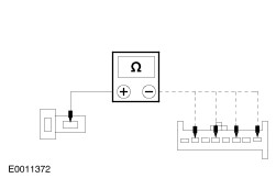
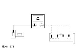
TEST the system for normal operation. No REPAIR the circuit in question. TEST the system for normal operation. | | PINPOINT TEST D : NO SOUND FROM ONE OR MORE OF THE SPEAKERS | | TEST CONDITIONS | DETAILS/RESULTS/ACTIONS | | D1: CHECK THE SPEAKER RESISTANCE | | | 1 Disconnect Inoperative Speaker. | | | 2 Measure the resistance between the inoperative speaker pin 1 and pin 2. | | | Is the resistance 6.0 ohms? Yes No INSTALL a new speaker(s).
REFER to: Front Door Speaker (415-03 Speakers, Removal and Installation).
TEST the system for normal operation. | | D2: CHECK SPEAKER POSITIVE CIRCUIT RESISTANCE - SPEAKER DISCONNECTED | | | 1 Disconnect Audio Unit C443b. | | | 2 Measure the resistance between the audio unit C443b and the inoperative speaker pins. - Left-hand front speaker inoperative: Pin 1, circuit 1-MD 10 (WH/BK), harness side and C938 pin 2, circuit 1-MD28 (WH), harness side.
- Left-hand rear speaker inoperative: Pin 3, circuit 1-MD 11 (VT/WH), harness side and C939 pin 2, circuit 1-MD29 (WH/VT), harness side.
- Right-hand front speaker inoperative: Pin 5, circuit 1-MD 17 (WH/RD), harness side and C937 pin 2, circuit 1-MD28 (WH), harness side.
- Right-hand rear speaker inoperative: Pin 7, circuit 1-MD 18 (WH), harness side and C1872 pin 2, circuit 1-MD29 (VT/WH), harness side.
| | | Is the resistance less than 1 ohm? Yes No REPAIR the circuit in question. TEST the system for normal operation. | | D3: CHECK SPEAKER RETURN CIRCUIT RESISTANCE - SPEAKER DISCONNECTED | | | 1 Measure the resistance between the audio unit C443b and the inoperative speaker pins. - Left-hand front speaker inoperative: Pin 2, circuit 2-MD 10 (GY/BK), harness side and C938 pin 1, circuit 2-MD28 (GY), harness side.
- Left-hand rear speaker inoperative: Pin 4, circuit 2-MD 11 (GY/WH), harness side and C939 pin 1, circuit 2-MD29 (GY/WH), harness side.
- Right-hand front speaker inoperative: Pin 6, circuit 2-MD 17 (GY/RD), harness side and C937 pin 1, circuit 2-MD28 (GY), harness side.
- Right-hand rear speaker inoperative: Pin 8, circuit 2-MD 18 (GY), harness side and C1872 pin 1, circuit 2-MD29 (GY/WH), harness side.
| | | Is the resistance less than 1 ohm? Yes INSTALL a new speaker.
REFER to: Front Door Speaker (415-03 Speakers, Removal and Installation).
TEST the system for normal operation. IF the concern persists, TEST the system for normal operation. No REPAIR the circuit in question. TEST the system for normal operation. | | PINPOINT TEST E : THE CD CHANGER IS INOPERATIVE OR DOES NOT OPERATE CORRECTLY | | TEST CONDITIONS | DETAILS/RESULTS/ACTIONS | | E1: CHECK IN-LINE FUSE | | | 1 CHECK Fuse FB1 (3A). | | | 2 Check the 3 amp in line fuse for the CD changer. | | | Is the fuse OK? Yes No INSTALL a new fuse. TEST the system for normal operation. | | E2: TEST THE AUDIO UNIT TO CD CHANGER HARNESS | | | 1 Disconnect CD Changer C1875. | | | 2 Disconnect Audio Unit C443d. | | | 3 Carry out the CD changer harness component test, refer to the Component Test in this Section. | | | Is the audio unit to CD changer harness OK? Yes No REPAIR or INSTALL a new CD changer harness. TEST the system for normal operation. | | E3: CHECK FOR CORRECT OPERATION OF CD CHANGER | | | 1 Substitute a known good CD changer. | | | 2 Verify correct operation of the substitute CD changer. | | | Do all CD changer functions operate correctly? Yes INSTALL a new CD changer.
REFER to: Compact Disc (CD) Changer - Vehicles Without: Navigation System (415-01 Audio Unit, Removal and Installation).
TEST the system for normal operation. No REMOVE the substitute CD changer. INSTALL the original CD changer. INSTALL a new audio unit.
REFER to: Audio Unit (415-01 Audio Unit, Removal and Installation).
TEST the system for normal operation. | | PINPOINT TEST F : THE AUDIO UNIT DOES NOT OPERATE CORRECTLY | | TEST CONDITIONS | DETAILS/RESULTS/ACTIONS | | F1: CHECK THE VEHICLE SPEED SENSOR (VSS) INPUT TO THE AUDIO UNIT | | | 1 Disconnect Audio Unit C443c. | | | 2 Disconnect PCM C421 or VSS C823 (Diesel Only). | | | 3 Measure the resistance between the audio unit and the VSS (diesel engine only) or powertrain control module (PCM) (petrol engine only). - Vehicles with diesel engine: Measure the resistance between audio unit C443c pin 6, circuit 8-MD24 (WH/GN), harness side and VSS C823 pin 2, circuit 8-PC60 (WH/BU), harness side.
- Vehicles with petrol engine: Measure the resistance between audio unit C443c pin 6, circuit 8-MD24 (WH/GN), harness side and PCM C421 pin 28, circuit 8-RE22 (WH/VT), harness side.
| | | Is the resistance less than 1 ohm? Yes INSTALL a new audio unit.
REFER to: Audio Unit (415-01 Audio Unit, Removal and Installation).
TEST the system for normal operation. No REPAIR the circuit in question. TEST the system for normal operation. | | PINPOINT TEST G : THE AUDIO UNIT REMOTE CONTROL DOES NOT OPERATE CORRECTLY | | TEST CONDITIONS | DETAILS/RESULTS/ACTIONS | | G1: TEST THE AUDIO UNIT REMOTE CONTROL SWITCH FOR SHORT | | | 1 Disconnect Audio Unit Remote Control Switch (C1871). | | | 2 Measure the resistance between the audio unit remote control switch pins. - Measure the resistance between the audio unit remote control switch pin 1 and pin 7.
- Measure the resistance between the audio unit remote control switch pin 2 and pin 7.
- Measure the resistance between the audio unit remote control switch pin 3 and pin 7.
- Measure the resistance between the audio unit remote control switch pin 4 and pin 7.
- Measure the resistance between the audio unit remote control switch pin 5 and pin 7.
| | | Are the resistances greater than 10,000 ohms (open circuit)? Yes No INSTALL a new audio unit remote control switch. TEST the system for normal operation. | | G2: TEST THE AUDIO UNIT REMOTE CONTROL SWITCH FOR OPEN | | | 1 Measure the resistance between the audio unit remote control switch pins. - Measure the resistance between the audio unit remote control switch pin 1 and pin 7 while pressing the SEEK UP button.
- Measure the resistance between the audio unit remote control switch pin 2 and pin 7 while pressing the SEEK DOWN button.
- Measure the resistance between the audio unit remote control switch pin 3 and pin 7 while pressing the VOLUME DOWN button.
- Measure the resistance between the audio unit remote control switch pin 4 and pin 7 while pressing the VOLUME UP button.
- Measure the resistance between the audio unit remote control switch pin 5 and pin 7 while pressing the TAPE/DISC AUTOCHANGE button.
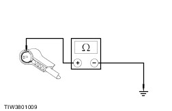
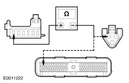
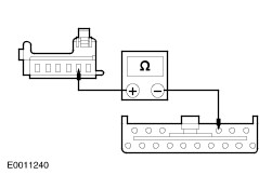
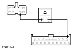
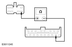
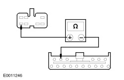
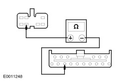
| | | Are the resistances less than 1 ohm? Yes No INSTALL a new audio unit remote control switch. TEST the system for normal operation. | | G3: CHECK CIRCUIT 4-MD27 (GY/WH) FOR OPEN | | | 1 Disconnect Audio Unit C443c. | | | 2 Disconnect Audio Unit Interface Module C86. | | | 3 Measure the resistance between audio unit C443c pin 1, circuit 4-MD27 (GY/WH), harness side and audio unit interface module C86 , circuit 4-MD27 (GY/WH), harness side. | | | Is the resistance less than 1 ohm? Yes No REPAIR the circuit. TEST the system for normal operation. | | G4: CHECK CIRCUIT 5-MD27 (BU/OG) FOR OPEN | | | 1 Measure the resistance between the audio unit C443c pin 2, circuit 5-MD27 (BU/OG), harness side and audio unit interface module C86, circuit 5-MD27 (BU/OG), harness side. | | | Is the resistance less than 1 ohm? Yes No REPAIR the circuit. TEST the system for normal operation. | | G5: CHECK CIRCUIT 7-MD15 (YE/GN) FOR OPEN | | | 1 Disconnect Audio Unit C443a. | | | 2 Measure the resistance between audio unit C443a pin 7, circuit 7-MD15 (YE/GN), harness side and audio unit interface module C86, circuit 7-MD15 (YE/GN), harness side. | | | Is the resistance less than 1 ohm? Yes No REPAIR the circuit. TEST the system for normal operation. | | G6: CHECK CIRCUITS 75-MD27 (YE/VT) AND 74-MD15 (BU/BK) FOR OPEN | | | 1 Disconnect Ignition Switch C456. | | | 2 Measure the resistance between ignition switch C456 pin 8, circuit 75-MD27 (YE/VT), harness side and audio unit interface module C86, circuit 74-MD15 (BU/BK), harness side. | | | Is the resistance less than 1 ohm? Yes No REPAIR the circuit. TEST the system for normal operation. | | G7: CHECK GROUND CIRCUIT 91-MD15 (BK/GN) FOR OPEN | | | 1 Measure the resistance between audio unit interface module C86, circuit 91-MD15 (BK/GN), harness side and ground. | | | Is the resistance less than 1 ohm? Yes No REPAIR the circuit. TEST the system for normal operation. | | G8: CHECK CIRCUIT 8-MD38 FOR OPEN | | | 1 Measure the resistance between audio unit remote control switch C1871 pin 3, circuit 8-MD38 (WH/RD), harness side and audio unit interface module C86, circuit 8-MD38 (WH/RD), harness side. | | | Is the resistance less than 1 ohm? Yes No REPAIR the circuit. TEST the system for normal operation. | | G9: CHECK CIRCUIT 10-MD38 (GY/RD) FOR OPEN | | | 1 Measure the resistance between audio unit remote control switch C1871 pin 4, circuit 10-MD38 (GY/RD), harness side and audio unit interface module C86, circuit 10-MD38 (GY/RD), harness side. | | | Is the resistance less than 1 ohm? Yes No REPAIR the circuit. TEST the system for normal operation. | | G10: CHECK CIRCUIT 8-MD26 (WH/BK) FOR OPEN | | | 1 Measure the resistance between the audio unit remote control switch C1871 pin 1, circuit 8-MD26 (WH/BK), harness side and audio unit interface module C86, circuit 8-MD26 (WH/BK), harness side. | | | Is the resistance less than 1 ohm? Yes No REPAIR the circuit. TEST the system for normal operation. | | G11: CHECK CIRCUIT 10-MD26 (GY/BK) FOR OPEN | | | 1 Measure the resistance between the audio unit remote control switch C1871 pin 2, circuit 10-MD26 (GY/BK), harness side and audio unit interface module C86, circuit 10-MD26 (GY/BK), harness side. | | | Is the resistance less than 1 ohm? Yes No REPAIR the circuit. TEST the system for normal operation. | | G12: CHECK CIRCUIT 8-MD39 (WH/BU) FOR OPEN | | | 1 Measure the resistance between audio unit remote control C1871 pin 5, circuit 8-MD39 (WH/BU), harness side and audio unit interface module C86, circuit 8-MD39 (WH/BU), harness side. | | | Is the resistance less than 1 ohm? Yes No REPAIR the circuit. TEST the system for normal operation. | | G13: CHECK CIRCUIT 9-MD26 (BN/YE) FOR OPEN | | | 1 Measure the resistance between the audio unit remote control switch C1871 pin 7, circuit 9-MD26 (BN/YE), harness side and audio unit interface module C86, circuit 9-MD26 (BN/YE), harness side. | | | Is the resistance less than 1 ohm? Yes INSTALL a new audio unit interface module. TEST the system for normal operation. No REPAIR the circuit. TEST the system for normal operation. | Component Tests CD Changer Harness NOTE:Refer to the Wiring Diagram, Section 415-01 for Schematic and Connector information. - Test the CD changer harness using the following table as a guide to meter lead placement as well as expected values.
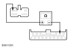
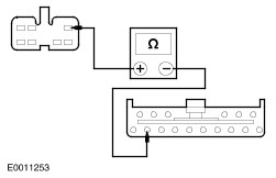
| CD Changer C1875 | Audio Unit C443d | Expected Value | | Pin 1 | Pin 1 | Less than 1 ohm | | Pin 3 | Pin 3 | Less than 1 ohm | | Pin 5 | Pin 5 | Less than 1 ohm | | Pin 6 | Pin 6 | Less than 1 ohm | | Pin 7 | Pin 7 | Less than 1 ohm | | Pin 8 | Pin 8 | Less than 1 ohm | | Pin 9 | Pin 9 | Less than 1 ohm | | Pin 10 | Pin 10 | Less than 1 ohm | | Pin 11 | Pin 11 | Less than 1 ohm | | Pin 12 | Pin 12 | Less than 1 ohm | | CD Changer C1875 | Negative Multimeter Lead | | | Pin 1 | Ground | Greater than 10,000 ohms (open circuit) | | Pin 3 | Ground | Greater than 10,000 ohms (open circuit) | | Pin 5 | Ground | Greater than 10,000 ohms (open circuit) | | Pin 6 | Ground | Greater than 10,000 ohms (open circuit) | | Pin 7 | Ground | Greater than 10,000 ohms (open circuit) | | Pin 8 | Ground | Greater than 10,000 ohms (open circuit) | | Pin 9 | Ground | Greater than 10,000 ohms (open circuit) | | Pin 10 | Ground | Greater than 10,000 ohms (open circuit) | | Pin 11 | Ground | Greater than 10,000 ohms (open circuit) | | Pin 12 | Ground | Greater than 10,000 ohms (open circuit) | - If routed here from a Pinpoint Test, return to the Pinpoint Test.
|