| Diagnosis and Testing Special Tool(s) | | Breakout box 29-001 | | | Test lead no. 12 33-010 | | | Adapter set for test probes 29-011A | Wiring diagram note For the wiring diagram and connector information, refer to the Wiring Diagram Manual, Sub-operations 413-01, 413-09, 417-02, 418-00A and 419-10, 501-11, 501-16, 700-02, 700-03, 700-04, 700-07. Testing and confirmation - The functions of the Central Timer Module (CTM) are explained in the "Description and Operation" section of this Sub-operation. Switch on the appropriate system to check the customer concern.
- Check for the following causes of electrical defects, in accordance with the customer concern:
Visual Inspection Chart | Electrical | - Connector contacts of the CTM
- Connector contacts of the central junction box (CJB)
- Door contact switch
- Wash/wipe switches
- Relays
| - If the concern still exists, carry out a module self-test (see self-test table).
- If the cause of the defect cannot be determined with the aid of the self-test, or if further tests are required, proceed in accordance with the Symptom Chart.
Symptom Chart | Symptom | Possible Sources | Action | | No module functions working | * Voltage supply. * Ground connection. * Central Timer Module (CTM) * Central Junction Box (CJB). * Circuit(s). | * Go to Pinpoint Test A. | | One of the module functions (lights-on warning, interior lighting timer, intermittent wiper, wash/wipe function, heated rear window timer, seat-belt warning) is not working/is malfunctioning | * See self-test table. | * Carry out a self-test. | | Interior lighting timer not working / malfunctioning - when the vehicle is unlocked with the remote control | * Anti-theft system/double locking module * CJB * CTM * Circuit(s). | * Go to Pinpoint Test D. | | Warning - transmission selector lever not in park position not working / malfunctioning | * Instrument panel auxiliary module. * CTM * CJB * Circuit(s). | * Go to Pinpoint Test F | | Warning buzzer on continuously - when driver's door is opened | * Transmission range switch (TR sensor). * CTM * CJB * Light switch. * Circuit(s). | * Go to Pinpoint Test H | | Warning buzzer on continuously | * CTM * CJB * Door contact. * Circuit(s). | * Self-test - test input signals. Go to Pinpoint Test I | Self-test Introduction to the Self Test Procedure NOTE:If switching cannot be carried out in self-test mode, either the heated rear window switch or the central timer module (CTM) itself is defective. If only the tests on the outputs cannot be carried out, either the multifunction switch or the CTM is defective. The central timer module (CTM) contains a self-test program with which most inputs and all outputs of the module can be checked. The following inputs cannot be checked using the self-test program: - Signal inputs from the ignition switch
- Wiper delay switch
- Remote unlocking input signal
- Ignition switch sensor (only for North American variant)
The self-test is divided into - Diagnostic mode for input signals
- Diagnostic mode for output signals
Both diagnostic modes can be called up by using the heated rear window switch and the multi-function switch. If the heated rear window switch is defective, the input self-test cannot be activated. If the multifunction switch is defective, the output test cannot be activated. To cancel the self-test turn the ignition off and back on again. Self-test procedure The self-test should be carried out in the indicated sequence. Preparatory Requirements - Switch off the ignition.
- Switch off all electrical consumers.
- Move interior light switch to "12 sec" setting.
- Apply handbrake.
- If the vehicle has a manual transmission set it to neutral, and if it has an automatic transmission set it to parking position "P".
- Close all doors.
- Do not operate the door handles.
On the non-European version: Clip the seat belt clip into the buckle. Input signal check The input signal check is activated in the following way: - Press and hold down the heated rear window switch.
- Switch on the ignition (do not start up the engine).
- Release the heated rear window switch.
Input Signal Check | Item No. | Check | Possible causes of defects | Action in case of a fault | | 1 | Open and close the driver's door. When the door is open, the acoustic signal must sound. | Door contact, CTM, CJB, circuit | Go to Pinpoint Test G | | 2 | Open and close the passenger door and then the rear doors. When the door is open, the acoustic signal must sound. | Door contact, CTM, CJB, circuit | Go to Pinpoint Test C. | | 3 | Switch the parking lights and the headlamps on and off. The warning buzzer should sound when the light is switched on. | Light switch, CTM, CJB, circuit | Go to Pinpoint Test B. | | 4 | Non-European variants only: Release the seat belt from the buckle and clip it back in again. The acoustic signal should sound when the belt is unbuckled. | Seat belt switch, CTM, CJB, circuit | Go to Pinpoint Test F in Sub-operation 413-01. | | 5 | Non-European variants only: Actuate the outer door handles of both front doors in turn. The acoustic signal should sound when the door handles are operated. | Door handle switch, CTM, CJB, circuit | Test wiring circuit of door handle switch to the CTM, pin 2. | | 6 | On all variants: briefly switch the wash/wiper system on and off using the wash/wiper lever. The warning buzzer should sound when the wash/wiper system is switched on. | Multifunction switch, CTM, CJB, circuit | Go to Pinpoint Test G in Sub-operation 501-16. | Output signal check - Move interior light switch to the "12 sec" setting.
- Set the wiper lever to "intermittent wipe".
- Inputs and outputs of the central timer module (CTM) are now inactive, i.e., for example, the interior lighting will not come on when a door is opened.
- If, during one of the following test steps, the acoustic signal of the CTM sounds, there is a break in the wiring circuit of the peripheral device in question.
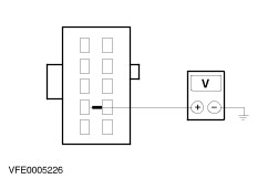
Output signal check | Item No. | Check | Possible causes of the defect | Action in case of a fault | | 1 | Press heated rear window switch briefly. The windscreen wipers operate continuously. Each time the wipers return to their rest position, the warning buzzer sounds briefly. | Windscreen wiper motor, CTM, CJB, circuit | Go to Pinpoint Test E in Sub-operation 501-16. | | 2 | Press the heated rear window switch briefly. The wipers remain in park position. | | | | 3 | Press the heated rear window switch briefly. The rear screen heating is switched on (using a multimeter check that there is a voltage across the heating wires). | Heated rear window relay, CTM, CJB, circuit | Go to Pinpoint Test G in Sub-operation 501-11. | | 4 | Press the heated rear window switch briefly. The rear window heating is switched off. | | | | 5 | Press the heated rear window switch briefly. The interior lights come on. | Interior lighting relay, CTM, CJB, circuit | Go to Pinpoint Test E. | | 6 | Press the heated rear window switch briefly. The interior lights are switched off. | | | | 7 | Non-European variants: press the heated rear window switch briefly. The seat belt warning light in the instrument cluster should light up. | Instrument cluster, CTM, CJB, circuit | Go to Pinpoint Test F in Sub-operation 413-01. | | 8 | Press the heated rear window switch briefly. The warning light is switched off. | | | | 9 | On all variants: set the wiper switch to OFF. | | | Pinpoint Test | PINPOINT TEST A : NO MODULE FUNCTIONS WORKING | | TEST CONDITIONS | DETAILS/RESULTS/ACTIONS | | A1: CHECK GROUND | | | 1 Ignition switch in position 0. | | | 2 Disconnect CTM (C23). | | | 3 Measure the resistance between CJB C23, pin 16, wiring harness side and ground. | | | Is the resistance lower than 5 ohm? Yes No | | A2: CHECK GROUND AT CJB | | | 1 Disconnect CJBC361. | | | 2 Measure the resistance between connector C361 (pin 10 from 08/98), circuit 31-CA23 (BK) (or 31-FA23 (BK) from 04/99), wiring harness side and ground. | | | Is the resistance lower than 5 ohm? Yes CHECK connections C23 and C361, if necessary RENEW CJB. CHECK operation of system No REPAIR ground connection in circuit 31-CA23 or 31-FA23. CHECK operation of system | | A3: CHECK VOLTAGE SUPPLY | | | 1 Measure the voltage between CJB C23, pin 18, (CJB side) and ground. | | | Is battery voltage displayed? Yes No | | A4: CHECK VOLTAGE SUPPLY | | | 1 Measure the voltage between CJB C370, circuit 30-DA4 (RD), wiring loom side and ground. | | | Is battery voltage displayed? Yes CHECK connections C23 and C370, if necessary RENEW CJB. CHECK operation of system No REPAIR circuit 30-DA4. CHECK operation of system | | A5: CHECK VOLTAGE SUPPLY | | | 1 Ignition switch in position II. | | | 2 Measure the voltage between CJB C23, pin 6, (CJB side) and ground. | | | Is battery voltage displayed? Yes CHECK connection C23, if necessary RENEW CTM. CHECK operation of system No CHECK connections C23 and C372, if necessary RENEW CJB. CHECK operation of system | | PINPOINT TEST B : LIGHT SWITCH SIGNAL WAS NOT DETECTED DURING SELF-TEST | | TEST CONDITIONS | DETAILS/RESULTS/ACTIONS | | B1: CHECK LICENCE PLATE LAMP | | | 1 Switch on dipped beam. | | | Is licence plate lamp working? Yes No REFER to Section 417-01 Exterior Lighting., Pinpoint Test D in the "Parking light, tail lamps or licence plate lamp" diagnosis section. | | B2: CHECK CJB | | | 1 Ignition switch in position 0. | | | 2 Disconnect CTM (C23). | | | 3 Disconnect CJBC361. | | | 4 Measure the resistance at the CJB between C361, pin 4 and C23, pin 7, CJB side. | | | Is the resistance lower than 1 ohm? Yes CHECK connection C23, if necessary RENEW CTM. Check operation of system No CHECK connection C361, if necessary RENEW CJB. Check operation of system | | PINPOINT TEST C : DOOR CONTACT FOR PASSENGER DOOR OR REAR DOOR(S) WAS NOT DETECTED DURING SELF-TEST | | TEST CONDITIONS | DETAILS/RESULTS/ACTIONS | | C1: EVALUATE SELF-TEST | | | 1 Evaluate self-test | | | Is self-test negative for all three doors (i.e. is there no acoustic signal for all three doors)? Yes Vehicles with auxiliary warning system as of 01/97: GO to C2. Vehicles without auxiliary warning system as of 01/97: GO to C6. No no signal for passenger door only, vehicles with auxiliary warning system as of 01/97: GO to C8. no signal for passenger door only, vehicles without auxiliary warning system or with auxiliary warning system up to 01/97: GO to C11. no signal for left-hand rear door only, vehicles with auxiliary warning system as of 01/97: GO to C12. no signal for left-hand rear door only, vehicles without auxiliary warning system or with auxiliary warning system up to 01/97: GO to C15. no signal for right-hand rear door only, vehicles with auxiliary warning system as of 01/97: GO to C16. no signal for right-hand rear door only, vehicles without auxiliary warning system or with auxiliary warning system up to 01/97: GO to C19. for both rear doors up to 01/97: REPAIR circuit 31S-LC26 (BK/OG). CHECK operation of system For right-hand front door and right-hand rear door from 01/97: REPAIR circuit 31-DA25 (BK). CHECK operation of system For right-hand front door and right-hand rear door from 08/98: REPAIR circuit 31S-LC14 (BK/OG). CHECK operation of system | | C2: CHECK OPERATION OF GRAPHIC DOOR WARNING DISPLAY | | | 1 Ignition switch in position II. | | | 2 If graphic door warning display in auxiliary warning system module is working, then the door contacts, the wiring and the auxiliary warning system module are OK. | | | Is graphic door warning display working for the three doors? Yes No RENEW auxiliary warning system module. CHECK operation of system | | C3: CHECK AUXILIARY WARNING SYSTEM MODULE | | | 1 Ignition switch in position 0. | | | 2 Disconnect Auxiliary warning system module C467a. | | | 3 Move interior light to the "12 sec." setting, connect connector C467a to breakout box using test lead no. 12, (33010) and bridge pin 21 (LHD) or pin 16 (RHD) to ground through 2 A fuse. | | | Does interior light come on for approx. 12 seconds? Yes CHECK connection C467a, if necessary RENEW auxiliary warning system module. CHECK operation of system No | | C4: CHECK CIRCUIT 31S-LC21 OR 31S-LC29 FOR BREAK | | | 1 Ignition switch in position 0. | | | 2 Disconnect CTM (C23). | | | 3 Measure resistance between breakout box pin 21 (LHD) or pin 16 (RHD) and CJB, socket C23, pin 1, circuit 31S-LC29 (BK/RD) (LHD) or 31S-LC21 (BK/GN) (RHD). | | | Is the resistance lower than 5 ohm? Yes CHECK connection C23, if necessary RENEW CTM. Check operation of system No | | C5: CHECK CJB | | | 1 Measure resistance between CJB C366 (pin 2 from 08/98) and C23, pin 1. | | | Is the resistance lower than 1 ohm? Yes REPAIR circuit 31S-LC21 or 31S-LC29. Check operation of system No CHECK connection C366, if necessary RENEW CJB. Check operation of system | | C6: CHECK CIRCUIT 31S-LC30 FOR BREAK | | | 1 Ignition switch in position 0. | | | 2 Disconnect CTM (C23). | | | 3 Open all doors and measure resistance between CJB C23, pin 1 and ground. | | | Is the resistance lower than 5 ohm? Yes CHECK connection C23, if necessary RENEW CTM. Check operation of system No | | C7: CHECK CJB | | | 1 Disconnect CJBC366. | | | 2 Measure resistance between CJB, socket C23, pin 1 and CJB, connector C366 (pin 9 from 08/98). | | | Is the resistance lower than 5 ohm? Yes REPAIR circuit 31S-LC30 (BK/GN). CHECK operation of system No CHECK connection C366, if necessary RENEW CJB. CHECK operation of system | | C8: CHECK OPERATION OF GRAPHIC DOOR WARNING DISPLAY | | | 1 Ignition switch in position II. | | | 2 Open passenger door and check operation of graphic door warning display. | | | Does the passenger door segment in the auxiliary warning system module light up? Yes CHECK connection C467a, if necessary RENEW auxiliary warning system module. CHECK operation of system No | | C9: CHECK CIRCUIT 31S-WC23 AND 31S-LC9 OR 31S-WC25 AND 31S-LC21 FOR BREAK | | | 1 Ignition switch in position 0. | | | 2 Disconnect Door contact switch C1975 or C1976. | | | 3 Disconnect Auxiliary warning system module C467. | | | 4 Connect connector C467a to breakout box using test lead no. 12, 33010 and measure resistance between - LHD: Breakout box, pin 15, circuit 31S-WC25 (BK/BU) and connector C1976, pin 1, circuit 31-LC21 (BK/GN).
- RHD: Breakout box, pin 20, circuit 31S-WC23 (BK/YE) and connector C1975, pin 1, circuit 31-LC9 (BK/RD).
| | | Is the resistance lower than 5 ohm? Yes No REPAIR corresponding circuit. CHECK operation of system | | C10: CHECK DOOR CONTACT | | | 1 Measure resistance at door contact switch between pin 1 and pin 2. | | | Is the resistance lower than 1 ohm when not actuated and higher than 10 kohm when actuated? Yes REPAIR circuit 31-LC21 (BK) (LHD) or 31-LC9 (BK) (RHD). CHECK operation of system No CHECK connection C1975 or C1976, if necessary RENEW door contact switch. CHECK operation of system | | C11: CHECK CIRCUIT 31S-LC9 OR 31S-LC21 FOR BREAK | | | 1 Ignition switch in position 0. | | | 2 Disconnect CTM (C23). | | | 3 Disconnect C1976 / C1975 or C685 / C684. | | | 4 Measure resistance between CJB C23, pin 1 and door contact switch, passenger side. | | | Is the resistance lower than 5 ohm? Yes Vehicles up to 01/97: Clean ground contact on door contact switch, if necessary RENEW door contact switch. Check operation of system No LHD from 08/98: REPAIR circuit 31S-LC21 (BK/GN), 31S-LC26 (BK/OG) or 31S-MB47 (BK/BU). Check operation of system LHD from 04/99: REPAIR circuit 31S-LC21 (BK/GN), 31S-LC26 (BK/OG) or 31S-GL47 (BK/BU). Check operation of system All other vehicles: REPAIR circuit 31S-LC21 (BK/GN) (LHD) or 31S-LC9 (BK/RD) (RHD). Check operation of system | | C12: CHECK OPERATION OF GRAPHIC DOOR WARNING DISPLAY | | | 1 Ignition switch in position II. | | | 2 Open left-hand rear door and check operation of graphic door warning display. | | | Does left-hand rear door segment in auxiliary warning system module light up? Yes CHECK connection C467a, if necessary RENEW auxiliary warning system module. CHECK operation of system No | | C13: CHECK CIRCUIT 31S-WC24 AND 31S-LC14 FOR BREAK | | | 1 Join connector C467a to the breakout box using test cable no.12, 33010 and measure the resistance between the breakout box, pin 23, circuit 31S-WC24 (BK/OG) and the door contact switch, connector C1980, pin 1, circuit 31S-LC14 (BK/OG), wiring harness side. | | | Is the resistance lower than 5 ohm? Yes No REPAIR circuit 31S-LC14 or 31S-WC24. CHECK operation of system | | C14: CHECK DOOR CONTACT | | | 1 Measure resistance at door contact switch between pin 1 and pin 2. | | | Is the resistance lower than 1 ohm when not actuated and higher than 10 kohm when actuated? Yes REPAIR circuit 31-LC14 (BK). CHECK operation of system No CHECK connection C1980, if necessary RENEW door contact switch. CHECK operation of system | | C15: CHECK CIRCUIT 31S-LC14 FOR BREAK | | | 1 Ignition switch in position 0. | | | 2 Disconnect CTM (C23). | | | 3 Disconnect Door contact switch C1980 or C687. | | | 4 Measure resistance between CJB C23, pin 1 and left-hand rear door contact switch. | | | Is the resistance lower than 5 ohm? Yes Vehicles up to 01/97: Clean ground contact on door contact switch, if necessary RENEW door contact switch. CHECK operation of system No REPAIR circuit 31S-LC14 (BK/OG). CHECK operation of system | | C16: CHECK OPERATION OF GRAPHIC DOOR WARNING DISPLAY | | | 1 Ignition switch in position II. | | | 2 Open right-hand rear door and check operation of graphic door warning display. | | | Does right-hand rear door segment in auxiliary warning system module light up? Yes CHECK connection C467a, if necessary RENEW auxiliary warning system module. CHECK operation of system No | | C17: CHECK CIRCUIT 31S-WC26 AND 31S-LC26 FOR BREAK | | | 1 Join connector C467a to the breakout box using test cable no.12, 33010 and measure the resistance between the breakout box, pin 7, circuit 31S-WC26 (BK/GN) and the door contact switch, connector C1979, pin 1, circuit 31S-LC26 (BK/GN), wiring harness side. | | | Is the resistance lower than 5 ohm? Yes No REPAIR circuit 31S-LC26 or 31S-WC26. CHECK operation of system | | C18: CHECK DOOR CONTACT | | | 1 Measure resistance at door contact switch between pin 1 and pin 2. | | | Is the resistance lower than 1 ohm when not actuated and higher than 10 kohm when actuated? Yes REPAIR circuit 31-LC26 (BK). CHECK operation of system No CHECK connection C1979, if necessary RENEW door contact switch. CHECK operation of system | | C19: CHECK CIRCUIT 31S-LC26 FOR BREAK | | | 1 Ignition switch in position 0. | | | 2 Disconnect CTM (C23). | | | 3 Disconnect C1979 or C686. | | | 4 Measure resistance between CJB C23, pin 1 and right-hand rear door contact switch. | | | Is the resistance lower than 5 ohm? Yes Vehicles up to 01/97: Clean ground contact on door contact switch, if necessary RENEW door contact switch. CHECK operation of system No REPAIR circuit 31S-LC26 (BK/OG). CHECK operation of system | | PINPOINT TEST D : INTERIOR LIGHTING TIMER NOT WORKING / MALFUNCTIONING - WHEN VEHICLE IS UNLOCKED WITH REMOTE CONTROL | | TEST CONDITIONS | DETAILS/RESULTS/ACTIONS | | D1: CHECK ANTI-THEFT SYSTEM/DOUBLE LOCKING MODULE | | | 1 Ignition switch in position 0. | | | 2 Disconnect C1966a or C451c. | | | 3 Move interior light switch to the "12 sec." setting. | | | 4 Close all doors from the inside and wait until interior light goes out. | | | 5 Bridge connector C451c, pin 8 (up to 01/97) or C1966a, pin 4 (as of 01/97) to ground for approx. 2 seconds through fuse (2 A). | | | Is interior light on for approx. 12 seconds? Yes CHECK connection C451c or C1966a, CHECK that unlocking operates, if necessary RENEW the anti-theft system/double locking module. CHECK operation of system No | | D2: CHECK CIRCUIT 8-AA36 FOR BREAK | | | 1 Disconnect CTM (C23). | | | 2 Measure the resistance between CJB C23, pin 19 and the anti-theft system/double locking module C451c, pin 8 (to 01/97) or C1966a, pin 4, circuit 8-AA36 (WH), wiring harness side. | | | Is the resistance lower than 5 ohm? Yes CHECK connection C23, if necessary RENEW CTM. Check operation of system No | | D3: CHECK CJB | | | 1 Disconnect CJBC366. | | | 2 Measure resistance at the CJB, between socket C23, pin 19 and connector C366 (pin 3 from 08/98). | | | Is the resistance lower than 1 ohm? Yes REPAIR circuit 8-AA36. Check operation of system No CHECK connection C366, if necessary RENEW CJB. Check operation of system | | PINPOINT TEST E : INTERIOR LIGHTING IS NOT ACTIVATED DURING SELF-TEST | | TEST CONDITIONS | DETAILS/RESULTS/ACTIONS | | E1: CHECK CTM | | | 1 Ignition switch in position 0. | | | 2 Disconnect CTM (C23). | | | 3 On CJB, bridge connector C23, pin 9 to ground through 2 A fuse. | | | Does interior lighting come on? Yes CHECK connection C23, if necessary RENEW CTM. Check operation of system No | | E2: CHECK INTERIOR LIGHTING RELAY | | | 1 Disconnect Interior lighting relay C57. | | | 2 On CJB, bridge connector C57, pin 3 and 5 through 2 A fuse. | | | Does interior lighting come on? Yes No | | E3: CHECK VOLTAGE SUPPLY AT INTERIOR LIGHTING RELAY | | | 1 Measure voltage between CJB connector C57, pin 2 and ground. | | | Is battery voltage displayed? Yes No CHECK connection C57, if necessary RENEW CJB. CHECK operation of system | | E4: CHECK GROUND AT INTERIOR LIGHTING RELAY | | | 1 Measure resistance between CJB connector C57, pin 5 and ground. | | | Is the resistance lower than 5 ohm? Yes CHECK connection C57, if necessary RENEW interior lighting relay. CHECK operation of system No | | E5: CHECK GROUND AT CJB | | | 1 Measure the resistance between CJB connector C361 (pin 10 from 08/98), circuit 31-CA23 (BK) (or 31-FA23 (BK) from 04/99), wiring harness side and ground. | | | Is the resistance lower than 5 ohm? Yes Vehicles without footwell lighting: CHECK connection C361, if necessary RENEW CJB. CHECK operation of system Vehicles with footwell lighting: GO to E7. No REPAIR circuit 31-CA23 or 31-FA23. CHECK operation of system | | E6: CHECK CJB | | | 1 Measure resistance at CJB between C57, pin 1 and C23, pin 9. | | | Is the resistance lower than 1 ohm? Yes CHECK connection C57, if necessary RENEW interior lighting relay. CHECK operation of system No CHECK connection C23, if necessary RENEW CJB. Check operation of system | | E7: CHECK CJB | | | 1 Ignition switch in position 0. | | | 2 Connect Interior lighting relay C57. | | | 3 Ignition switch in position II. | | | 4 Bridge connector C367, wiring harness side, to ground through 2 A fuse. | | | Does interior lighting come on? Yes CHECK connection C367, if necessary RENEW CJB. Check operation of system No REPAIR circuit 31S-LB3 (BK/BU) or 31S-LB13 (BK/BU). Check operation of system | | PINPOINT TEST F : WARNING - TRANSMISSION SELECTOR LEVER NOT IN PARK POSITION NOT WORKING / MALFUNCTIONING | | TEST CONDITIONS | DETAILS/RESULTS/ACTIONS | | F1: DETERMINE THE CONDITIONS OF THE DEFECT | | | 1 Determine whether the warning is not operating or the warning signal is sounding for no reason. | | | Is warning signal not sounding even though the driver's door is open and the transmission selector lever is not in the park position? Yes No Warning signal is sounding continuously even though the transmission selector lever is in the park position: GO to H1. | | F2: CHECK OPERATION OF INTERIOR LIGHTING TIMER | | | 1 Open driver's door and check whether interior lighting is switched on for approx. 12 seconds. | | | Is interior lighting switched on? Yes No Carry out a self-test. | | F3: CHECK INPUT SIGNAL FROM INSTRUMENT PANEL AUXILIARY MODULE | | | 1 Transmission selector lever must not be in the "P" position. | | | 2 Ignition switch in position 0. | | | 3 Disconnect CTM (C23). | | | 4 Measure resistance between CJB C23, pin 8 and ground. | | | Is the resistance lower than 5 ohm? Yes CHECK connection C23, if necessary RENEW CTM. Check operation of system No | | F4: CHECK CIRCUIT 8-WC10 (8-GE53 FROM 04/99) | | | 1 Disconnect Instrument panel auxiliary module C440. | | | 2 Connect connector of instrument panel auxiliary module to breakout box (29-001) using test lead no. 12 (33-010). Measure resistance between breakout box, pin 27 and CJB C23, pin 8, circuit 8-WC10 (WH/VT) (8-GE53 (WH/VT) from 04/99). | | | Is the resistance lower than 5 ohm? Yes Selector lever locking system operates: CHECK connection C440, if necessary RENEW instrument panel auxiliary module. Check operation of system Selector lever locking system does not work: Go to Pinpoint Test D in the "Instrument panel auxiliary module" diagnosis section in this Sub-operation. No REPAIR circuit 8-WC10 or 8-GE53. CHECK operation of system | | PINPOINT TEST G : DOOR CONTACT - DRIVER'S DOOR NOT DETECTED IN SELF-TEST | | TEST CONDITIONS | DETAILS/RESULTS/ACTIONS | | G1: DETERMINE THE BUILD DATE | | | 1 Determine the build date. | | | Was the vehicle built after 01/97? Yes with auxiliary warning system: GO to G2. without auxiliary warning system: GO to G8. No | | G2: CHECK OPERATION OF WARNING LIGHT - DRIVER'S DOOR OPEN | | | 1 Open driver's door. | | | Does driver's door warning light in auxiliary warning system module operate? Yes No | | G3: CHECK AUXILIARY WARNING SYSTEM MODULE | | | 1 Ignition switch in position 0. | | | 2 Disconnect Auxiliary warning system module C467a. | | | 3 Open driver's door, connect connector C467a to breakout box using test lead no. 12, (33010) and bridge pin 18 to ground through 2A fuse. | | | Does interior lighting come on? Yes CHECK connection C467, if necessary RENEW auxiliary warning system module. Check operation of system No | | G4: CHECK CIRCUIT 31S-LC30 FOR BREAK | | | 1 Disconnect CTM (C23). | | | 2 Measure resistance between breakout box, pin 18 and CJB, connector C23, pin 2, circuit 31S-LC30 (BK/GN). | | | Is the resistance lower than 5 ohm? Yes CHECK connection C23, if necessary RENEW CTM. Check operation of system No | | G5: CHECK CJB | | | 1 Disconnect CJBC366. | | | 2 Measure resistance at the CJB between C366 (pin 9 from 08/98) and C23, pin 2. | | | Is the resistance lower than 5 ohm? Yes REPAIR circuit 31S-LC30 (BK/GN). CHECK operation of system No CHECK connection C366, if necessary RENEW CJB. Check operation of system | | G6: CHECK INPUT SIGNAL | | | 1 Ignition switch in position 0. | | | 2 Disconnect Auxiliary warning system module C467a. | | | 3 Open driver's door, connect connector C467a to breakout box using test lead no. 12, (33010) and measure resistance between pin 20 (LHD) or pin 15 (RHD) and ground. | | | Is the resistance lower than 5 ohm? Yes CHECK connection C467a, if necessary RENEW auxiliary warning system module. Check operation of system No | | G7: CHECK CIRCUIT 31S-WC23 AND 31S-LC9 OR 31S-WC25 AND 31S-LC21 | | | 1 Disconnect C1975 or C1976. | | | 2 Measure resistance between breakout box, pin 20, circuit 31S-WC23 (BK/YE) and connector C1975, pin 1, circuit 31S-LC9 (BK/RD), wiring harness side (LHD) or breakout box, pin 15, circuit 31S-WC25 (BK/BU) and connector C1976, pin 1, circuit 31S-LC21 (BK/GN), wiring harness side (RHD). | | | Is the resistance lower than 5 ohm? Yes No REPAIR circuit 31S-WC23 and 31S-LC9 or 31-WC25 and 31S-LC21. CHECK operation of system | | G8: CHECK INPUT SIGNAL | | | 1 Ignition switch in position 0. | | | 2 Disconnect CTM (C23). | | | 3 Open the driver door and measure the resistance between CJB, socket C23, pin 2 and ground. | | | Is the resistance lower than 5 ohm? Yes CHECK connection C23, if necessary RENEW CTM. CHECK operation of system No | | G9: CHECK CIRCUIT 31S-LC9(A) OR 31S-LC21(A) FOR BREAK | | | 1 Disconnect C1975 or C1976. | | | 2 Measure resistance between CJB C23, pin 2 and connector C1975, pin 1, circuit 31S-LC9 (BK/RD), wiring harness side (LHD) or C1976, pin 1, circuit 31S-LC21 (BK/GN), wiring harness side (RHD). | | | Is the resistance lower than 5 ohm? Yes No REPAIR circuit 31S-LC9(A) or 31S-LC21(A). CHECK operation of system | | G10: CHECK DOOR CONTACT | | | 1 Measure resistance at door contact switch between pin 1 and 2. | | | Is the resistance lower than 5 ohm when not actuated and higher than 10 kohm when actuated? Yes REPAIR circuit 31-LC9 (BK) (LHD) or 31-LC21 (BK) (RHD). CHECK operation of system No CHECK connection C1975 or C1976, if necessary RENEW door contact switch. CHECK operation of system | | G11: CHECK INPUT SIGNAL | | | 1 Ignition switch in position 0. | | | 2 Disconnect CTM (C23). | | | 3 Open driver's door and measure resistance between CJB C23, pin 2 and ground. | | | Is the resistance lower than 5 ohm? Yes CHECK connection C23, if necessary RENEW CTM. CHECK operation of system No | | G12: CHECK CIRCUIT 31S-LC9 OR 31S-LC21 FOR BREAK | | | 1 Disconnect C685 or C684. | | | 2 Measure resistance between CJB C23, Pin 2 and connector C685, circuit 31S-LC9 (BK/RD), wiring harness side (LHD) or C684, circuit 31S-LC21 (BK/GN), wiring harness side (RHD). | | | Is the resistance lower than 5 ohm? Yes No | | G13: CHECK CJB | | | 1 Disconnect CJBC366. | | | 2 Measure resistance at the CJB between C366 (pin 2 from 08/98) and C23, pin 2. | | | Is the resistance lower than 5 ohm? Yes REPAIR circuit 31S-LC9 or 31S-LC21. CHECK operation of system No CHECK connection C366, if necessary RENEW CJB. CHECK operation of system | | G14: CHECK DOOR CONTACT | | | 1 Measure resistance at door contact switch between pin 1 and 2. | | | Is the resistance lower than 5 ohm when not actuated and greater than 10 kohm when actuated? Yes REPAIR ground connection to door contact. CHECK operation of system No CHECK connection C818 or C819, if necessary RENEW door contact switch. CHECK operation of system | | PINPOINT TEST H : WARNING BUZZER SOUNDS WHEN DRIVER'S DOOR IS OPENED | | TEST CONDITIONS | DETAILS/RESULTS/ACTIONS | | H1: DETERMINE THE CONDITIONS OF THE DEFECT | NOTE:If the acoustic signal sounds when the driver's door is opened, even though the light switch is switched off and, on vehicles with automatic transmission, the selector lever is in the park position, there is a defect. | | | 1 Ignition switch in position 0. | | | 2 Disconnect CTM (C23). | | | Do the licence plate lights come on even though the light switch is switched off? Yes No Vehicles with automatic transmission GO to H3. Vehicles with manual transmission: CHECK connection C23, if necessary RENEW CTM. CHECK operation of system | | H2: CHECK LIGHT SWITCH. | | | 1 Connect CTM (C23). | | | 2 Disconnect Light switch (C320). | | | Does the acoustic warning signal stop and do the licence plate lights go out? Yes Renew light switch. Check operation of system No LOCATE and REPAIR short to ground in circuit 30S-DD40 (RD/GN), 30S-DA40 (RD/GN) or 30S-DA30 (RD/WH). CHECK operation of system | | H3: DETERMINE THE CONDITIONS OF THE DEFECT | | | 1 Ignition switch in position 0. | | | 2 Put the transmission selector lever in the park position. | | | Can the ignition key be removed? Yes No Go to Pinpoint Test E in the diagnosis section for the instrument panel auxiliary module. | | H4: CHECK INSTRUMENT PANEL AUXILIARY MODULE | | | 1 Connect CTM (C23). | | | 2 Disconnect Instrument panel auxiliary module C440. | | | Does acoustic warning signal stop? Yes CHECK connection C440, if necessary RENEW instrument panel auxiliary module. Check operation of system No | | H5: CHECK CIRCUIT 8-WC10 (8-GE53 FROM 04/99) FOR SHORT TO BATTERY VOLTAGE | | | 1 Disconnect CJB C23. | | | 2 Measure voltage between CJB C23, pin 8 and ground. | | | Is battery voltage displayed? Yes No CHECK connection C23, if necessary RENEW CTM. CHECK operation of system | | H6: CHECK CJB | | | 1 Disconnect CJB C372. | | | 2 Measure voltage between connector C372, pin 2, circuit 8-WC10 (WH/VT) (8-GE53 (WH/VT) from 04/99), wiring harness side and ground. | | | Is voltage displayed? Yes All other vehicles: REPAIR circuit 8-WC10. CHECK operation of system No CHECK connection C372, if necessary RENEW CJB. CHECK operation of system | | H7: CHECK THE ANTI-THEFT SYSTEM/CENTRAL LOCKING MODULE | | | 1 Disconnect Anti-theft system/central locking module C1966b. | | | 2 Measure voltage between connector C372, pin 2, circuit 8-GE53 (WH/VT), wiring harness side and ground. | | | Is voltage displayed? Yes REPAIR circuit 8-GE53, 29S-GM7 (OG/WH) or 29S-GM7A (OG/WH). CHECK operation of system. No CHECK connection C372, if necessary RENEW CJB. CHECK operation of system | | PINPOINT TEST I : WARNING BUZZER SOUNDS CONTINUOUSLY | | TEST CONDITIONS | DETAILS/RESULTS/ACTIONS | | I1: CREATE OUTPUT CONDITIONS | | | 1 Ignition switch in position II. | | | 2 Create the following output conditions: - Put transmission selector lever into the park position (only for automatic transmissions)
- Switch wiper lever to the OFF position
- Switch off heated rear window
| | | Does acoustic warning signal stop when the ignition is switched off? Yes Vehicles with seat belt warning system, seat belt warning light in instrument cluster comes on: REFER to Section 413-01 Instrument Cluster. Vehicles without seat belt warning system or vehicles with seat belt warning system whose seat belt warning light in instrument panel does not come on: CHECK connection C23, if necessary RENEW CTM. CHECK operation of system No CHECK connection C23, if necessary RENEW CTM. CHECK operation of system | |