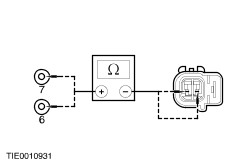
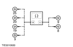
| Diagnosis and Testing Refer to Wiring Diagrams Section 501-20, for schematic and connector information. Special Tool(s) | | Simulator, Air Bag 418-037(40-001) | | | Simulator Air Bag/ Pyrotechnic Safety Belt 418-047A (40-004A) | | | Simulator, Side Air Bag 418-133 (40-009) | | | Test and Deployment Lead Air Bag/Pyrotechnic Safety Belt 418-S055 (40-007A) | | | Terminal Probe Kit 418-S035 (29-011A) | | | Breakout Box 418-S006 (29-001) | | | Test Lead No.12, AWS, PAS, Air Bag 418-006-15 (33-010) | | | Test Lead Adaptor For Test Lead No. 12, Air Bag Module 418-006-17 (40-002A) | General Equipment Wordlwide diagnostic system (WDS) Diagnosing Customer Concerns Without Hard Lamp Fault Codes (LFCs) WARNING:The back up power supply must be depleted, before any work is carried out on the supplemental restraint system. Wait at least one minute after disconnecting the battery ground cable. Failure to follow this instruction may result in personal injury. NOTE:Following the pinpoint tests when a lamp fault code (LFC) is not present, will result in needless replacement of air bag system components and repeat repairs. Speak with the customer to determine if a particular set of conditions must be met in order for a fault to occur. If a LFC is reported by the customer but is not present when the vehicle comes in for repair, pinpoint test diagnostics cannot be used. Instruct the customer on how to count a LFC. Diagnosing Customer Concerns with Hard LFCs WARNING:Do not use substitute air bag simulators when working on the supplemental restraint system. Use only the appropriate tool. Failure to follow this instruction may result in personal injury. Most air bag system diagnostic procedures require the use of system deactivation and system reactivation procedures. These procedures require the air bag module(s) and safety belt buckle pretensioners to be disconnected from the SRS, thereby removing the risk of air bag deployment while diagnostics are carried out. Air bag simulators are required to carry out diagnosis and testing of the air bag system. The simulator contains a resistor, used to simulate an air bag module connection to the system. It is not acceptable to short-circuit the air bag module connections with a 0 ohm jumper wire. If a 0 ohm jumper wire is used to short-circuit the air bag module connections, a LFC will be displayed and a DTC logged by the air bag control module. Deactivation WARNING:The back up power supply must be depleted, before any work is carried out on the supplemental restraint system. Wait at least one minute after disconnecting the battery ground cable. Failure to follow this instruction may cause personal injury. - Disconnect the battery ground cable.
REFER to: Battery Disconnect (414-01 Battery, Mounting and Cables, General Procedures).
- Wait at least one minute for the backup power supply in the air bag control module to deplete its stored energy.
-
WARNING:Place the air bag module(s) on a ground wired bench, with the trim cover facing up to avoid accidental deployment. Failure to follow this instruction may result in personal injury. Remove the driver air bag module from the vehicle.
REFER to: Driver Air Bag Module.
- Connect the driver air bag module simulator to the harness in place of the driver air bag module at the top of the steering column.
- Remove the passenger air bag module.
REFER to: Passenger Air Bag Module.
- Connect the passenger air bag module simulator to the harness in place of the passenger air bag module.
- Disconnect the driver side air bag module underseat connector.
- Connect the driver side air bag module simulator to the underseat floor harness in place of the side air bag module connector.
- Disconnect the passenger side air bag module underseat connector.
- Connect the passenger side air bag module simulator to the underseat floor harness in place of the side air bag module connector.
- Reconnect the battery ground cable.
REFER to: Battery Disconnect (414-01 Battery, Mounting and Cables, General Procedures).
Reactivation WARNING:The air bag simulators must be removed and the air bag modules reconnected when reactivated to avoid non-deployment in a collision. Failure to follow this instruction may result in personal injury. - Disconnect the battery ground cable.
REFER to: Battery Disconnect (414-01 Battery, Mounting and Cables, General Procedures).
- Wait at least one minute for the backup power supply in the air bag control module to deplete its stored energy.
- Remove the driver air bag module simulator from the harness at the top of the steering column.
- Reconnect and install the driver air bag module.
REFER to: Driver Air Bag Module.
- Remove the passenger air bag module simulator from the passenger air bag module harness.
- Reconnect and install the passenger air bag module.
REFER to: Passenger Air Bag Module.
- Remove the driver side air bag module simulator from the underseat connector.
- Reconnect the driver side air bag module underseat connector.
- Remove the passenger side air bag module simulator from the underseat connector.
- Reconnect the passenger side air bag module underseat connector.
- Reconnect the battery ground cable.
REFER to: Battery Disconnect (414-01 Battery, Mounting and Cables, General Procedures).
Glossary Air Bag Module Simulator Air bag module simulators are used to simulate air bag module connections to the system. Deactivate the System Deactivate the system means to carry out the deactivation procedure. Prove Out the System The air bag warning indicator will illuminate for approximately five seconds: - fail to illuminate
- illuminate continuously
- flash
Reactivate the System Reactivate the system means to carry out the reactivation procedure. Principles of Operations Supplemental Restraint System (SRS) Operation The supplemental restraint system is a single point sensing system, with remote side impact sensors, for vehicles equipped with side air bags. In the event of a severe frontal or angled impact, in excess of a predetermined limit, the driver and passenger front air bag(s) will deploy. In the event of a severe full side impact, in excess of a predetermined limit either the driver or passenger side air bag will deploy. Air bag deployment will only occur, in the event of a severe collision, when the ignition key is in the RUN position. Air Bag Control Module The air bag control module retains full control of the whole system, providing continual system checks and diagnostic capabilities. A visual warning indicator which is located in the instrument cluster, is illuminated when the ignition is switched ON for approximately five seconds then goes out. If a fault occurs, the warning indicator, depending on the nature of the fault, begins to flash or comes on continuously. In the event of a failure in the vehicle power supply during an accident, the air bag control module provides an auxiliary power supply, sufficient to deploy the front air bag(s) for a minimum of 150mS. The auxiliary power supply is discharged by the air bag control within 60 seconds of the battery ground cable being disconnected. Thus making sure the supplemental restraint system remains operational. The air bag control module contains a micro-controller to evaluate and process impact data and two sensors. An electronic accelerometer, which converts the actual acceleration and deceleration force, along the vehicles longitudinal axis, into electrical signals, and an electro - mechanical safing sensor which measures deceleration only. Provided both these sensors sense an impact in excess of a predetermined limit the safing sensor will close the circuit to deploy the front air bag module(s). The safing sensor retains the control function to prevent unintentional deployment of the frontal air bags(s). Side Impact Sensors The side impact sensors are mounted to the floor panel on either side of the vehicle, to facilitate remote lateral impact sensing. Each side impact sensor contains a micro-controller which processes signals from two accelerometers within the sensor. The side impact crash sensor processes the side impact data, initiating a deployment request to the air bag control module. The air bag control module processes this request against stored data, to deploy the side air bag on the side the deployment request was initiated. Air Bag Warning Indicator The air bag warning indicator is incorporated into the instrument cluster, together with the automatic detach detect (ADD) circuit. The air bag warning indicator comes on for five seconds at key ON. If the system self-tests OK the indicator extinguishes, if a fault is detected the indicator will flash, illuminate continually from key ON or not illuminate at all, depending on the nature of the fault. The ADD circuit is designed to illuminate the air bag warning indicator continuously, if the air bag control module circuit is broken, either by loss of power or ground supply or electrical connector disconnection. Inspection and Verification - Verify the customer concern by operating the system.
- Visually inspect for obvious signs of mechanical or electrical damage.
Visual Inspection Chart | Electrical | | Fuse(s) | | Electrical connector(s) | | Circuit(s) | | Wiring harness | | Air bag module(s) | | Bulb | - If an obvious cause for an observed or reported concern is found, correct the cause (if possible) before proceeding to the next step.
-
WARNING:Only the WDS digital multimeter is to be used to carry out diagnostic checks on supplemental restraint systems. Do not use any other digital multimeter. Failure to follow this instruction may result in personal injury. Check the warning indicator flash code and refer to the Symptom Chart. Symptom Chart Symptom Chart | Symptom | Possible Sources | Action | | No air bag indicator | * Instrument cluster. * Bulb. | * | | Air bag warning indicator on all the time | * Instrument cluster. * Circuit(s). * Air bag control module. | * | | Air bag warning indicator one flash cycle: Driver air bag module failure; driver air bag squib resistance out of range | * Driver air bag module. * Circuit(s). * Air bag sliding contact. | * | | Air bag warning indicator two flash cycle: Passenger air bag module failure; passenger air bag squib resistance out of range | * Passenger air bag module. * Circuit(s). | * | | Air bag warning indicator three flash cycle: Short to battery positive or ground in section of air bag squib circuit which is common to both driver and passenger air bag squib circuits | * Circuit(s). | * | | Air bag warning indicator four flash cycle: Safety belt buckle pretensioner failure; single or both safety belt buckle pretensioner(s) or circuit(s) | * Safety belt buckle pretensioner(s). * Circuit(s). | * | | Air bag warning indicator five flash cycle: Driver side air bag module failure; driver side air bag squib resistance out of range; short to battery positive or ground | * Driver side air bag module. * Circuit(s). | * | | Air bag warning indicator six flash cycle: Passenger side air bag module failure; passenger side air bag squib resistance out of range; short to battery positive or ground | * Passenger side air bag module. * Circuit(s). | * | | Air bag warning indicator seven flash cycle: Driver side impact sensor fault; side impact sensor circuit | * Driver side impact sensor. * Circuit(s). | * | | Air bag warning indicator eight flash cycle: Passenger side impact sensor fault; side impact sensor circuit | * Passenger side impact sensor. * Circuit(s). | * | Pinpoint Tests | PINPOINT TEST A : NO AIR BAG WARNING INDICATOR | | TEST CONDITIONS | DETAILS/RESULTS/ACTIONS | | A1: CHECK THE INSTRUMENT PANEL WARNING LIGHTS | | | 1 Ignition switch in position II. | | | 2 Check the warning light operation. | | | Do all other fuse 30 (7.5A) consumer fed warning lights operate? Yes No | | A2: CHECK THE AIR BAG WARNING LIGHT CIRCUIT FOR A SHORT TO GROUND | WARNING:WAIT AT LEAST ONE MINUTE AFTER DISCONNECTING THE BATTERY GROUND CABLE BEFORE DISCONNECTING ANY SUPPLEMENTAL RESTRAINT SYSTEM ELECTRICAL CONNECTORS. FAILURE TO FOLLOW THIS INSTRUCTION COULD LEAD TO PREMATURE AIR BAG DEPLOYMENT AND MAY RESULT IN PERSONAL INJURY. | WARNING:DO NOT TEST OR WORK ON THE SYSTEM UNLESS ALL THE AIR BAG MODULE AND PRETENSIONER SIMULATORS ARE INSTALLED. DO NOT PROBE THE TERMINALS OF AIR BAG COMPONENTS AS DEPLOYMENT AND PERSONAL INJURY MAY OCCUR. | | | 1 Ignition switch in position 0. | | | 2 Deactivate the supplemental restraint system. | | | 3 Disconnect the battery ground cable.
REFER to: Battery Disconnect (414-01 Battery, Mounting and Cables, General Procedures).
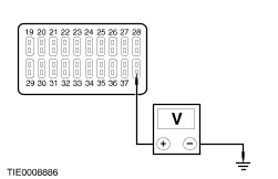
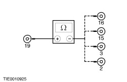
| | | 4 Disconnect Instrument Cluster C808a. | | | 5 Disconnect Air Bag Control Module C20. | | | 6 Connect the Breakout Box (BOB) to the air bag control module harness using the appropriate lead and adaptor. | | | 7 Measure the resistance between BOB pin 21, circuit 91S - MA14 (BK/GN) (BOB pin 11, circuit 91S - MA14 [BK/GN] with passenger and side air bags), harness side and ground. | | | Is the resistance greater than 10,000 ohms? Yes INSTALL a new automatic detach detect circuit/instrument cluster printed circuit.
REFER to: Instrument Cluster Printed Circuit - Vehicles With: Tachometer /
Instrument Cluster Printed Circuit - Vehicles Without: Tachometer.
REACTIVATE the supplemental restraint system. TEST the system for normal operation. No REPAIR circuit 91S - MA14 (BK/GN). REACTIVATE the supplemental restraint system. TEST the system for normal operation. | | A3: CHECK FUSE 30 (7.5A) | | | 1 CHECK Fuse 30 (7.5A). | | | 2 Check Fuse 30 (7.5A) | | | Is the fuse OK? Yes No INSTALL a new fuse, if the fuse fails, CHECK all consumers fed from fuse 30. REFER to fuse details. CHECK for a short to ground, REPAIR as necessary. | | A4: CHECK THE WARNING LIGHT GROUND CIRCUIT | WARNING:WAIT AT LEAST ONE MINUTE AFTER DISCONNECTING THE BATTERY GROUND CABLE BEFORE DISCONNECTING ANY SUPPLEMENTAL RESTRAINT SYSTEM ELECTRICAL CONNECTORS. FAILURE TO FOLLOW THIS INSTRUCTION COULD LEAD TO PREMATURE AIR BAG DEPLOYMENT AND MAY RESULT IN PERSONAL INJURY. | WARNING:DO NOT TEST OR WORK ON THE SYSTEM UNLESS ALL THE AIR BAG MODULE AND PRETENSIONER SIMULATORS ARE INSTALLED. DO NOT PROBE THE TERMINALS OF AIR BAG COMPONENTS AS DEPLOYMENT AND PERSONAL INJURY MAY OCCUR. | | | 1 Ignition switch in position 0. | | | 2 Deactivate the supplemental restraint system. | | | 3 Disconnect the battery ground cable.
REFER to: Battery Disconnect (414-01 Battery, Mounting and Cables, General Procedures).
| | | 4 Disconnect Instrument Cluster C808a. | | | 5 Measure the resistance between the instrument cluster C808a pin 13, circuit 91 - GG14 (BK/OG), harness side and ground. | | | Is the resistance less than 5 ohms? Yes No REPAIR circuit 91 - GG14 (BK/OG). REACTIVATE the supplemental restraint system. TEST the system for normal operation. | | A5: CHECK THE WARNING LIGHT SUPPLY CIRCUIT | | | 1 Connect the battery ground cable.
REFER to: Battery Disconnect (414-01 Battery, Mounting and Cables, General Procedures).
| | | 2 Ignition switch in position II. | | | 3 Measure the voltage between C808a pin 9, circuit 15–CG14A (GN/RD), harness side and ground. | | | Is the voltage greater than 10 volts? Yes Install a new automatic detach detect circuit/instrument cluster printed circuit.
REFER to: Instrument Cluster Printed Circuit - Vehicles With: Tachometer /
Instrument Cluster Printed Circuit - Vehicles Without: Tachometer.
REACTIVATE the supplemental restraint system. TEST the system for normal operation. No REPAIR circuit 15-GG14A (GN/RD). REACTIVATE the supplemental restraint system. TEST the system for normal operation. | | PINPOINT TEST B : AIR BAG WARNING LIGHT ON ALL THE TIME | | TEST CONDITIONS | DETAILS/RESULTS/ACTIONS | | B1: CHECK THE AIR BAG CONTROL MODULE FUSE | | | 1 CHECK Fuse 38 (7.5A). | | | Is the fuse OK? Yes No INSTALL a new fuse. If the fuse blows again, GO to B7. | | B2: CHECK THE SUPPLY VOLTAGE AT THE CENTRAL JUNCTION BOX (CJB) | | | 1 Ignition switch in position II. | | | 2 Measure the voltage between the input side of fuse 38 (7.5A) and ground. | | | Is the voltage greater than 9.5 volts? Yes No CHECK the battery and charging system.
REFER to: Charging System - Vehicles Built From: 05/1999.
TEST the system for normal operation. | | B3: CHECK THE AIR BAG CONTROL MODULE SUPPLY CIRCUIT | WARNING:WAIT AT LEAST ONE MINUTE AFTER DISCONNECTING THE BATTERY GROUND CABLE BEFORE DISCONNECTING ANY SUPPLEMENTAL RESTRAINT SYSTEM ELECTRICAL CONNECTORS. FAILURE TO FOLLOW THIS INSTRUCTION COULD LEAD TO PREMATURE AIR BAG DEPLOYMENT AND MAY RESULT IN PERSONAL INJURY. | WARNING:DO NOT TEST OR WORK ON THE SYSTEM UNLESS ALL THE AIR BAG MODULE AND PRETENSIONER SIMULATORS ARE INSTALLED. DO NOT PROBE THE TERMINALS OF AIR BAG COMPONENTS AS DEPLOYMENT AND PERSONAL INJURY MAY OCCUR. | | | 1 Deactivate the supplemental restraint system. | | | 2 Ignition switch in position 0. | | | 3 Disconnect the battery ground cable.
REFER to: Battery Disconnect (414-01 Battery, Mounting and Cables, General Procedures).
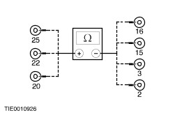
| | | 4 Disconnect Air Bag Control Module C20. | | | 5 Connect the Breakout Box (BOB) to the air bag control module harness using the appropriate lead and adaptor. | | | 6 Measure the resistance between the output side of fuse 38 (7.5A) and BOB pin 19, circuit 94 - MA10 (VT/OG). | | | Is the resistance less than 5 ohms? Yes No REPAIR circuit 94 - MA10 (VT/OG). REACTIVATE the supplemental restraint system. TEST the system for normal operation. | | B4: CHECK THE AIR BAG CONTROL MODULE GROUND CIRCUIT | NOTE:Make sure that the ground location is clean before testing. | | | 1 Measure the resistance between: - BOB pin 20, circuit 91 - MA10B (BK/RD) harness side and ground.
- BOB pin 25, circuit 91 - MA10C (BK/RD) with passenger and side air bag (BOB pin 22, circuit 91 - MA10A [BK/RD] without passenger air bag) harness side and ground.
| | | Are the resistances less than 5 ohms? Yes No REPAIR circuit 91 - MA10 (BK/RD); or circuit 91 - MA10A (BK/RD); or circuit 91 - MA10B (BK/RD); or circuit 91 - MA10C (BK/RD). REACTIVATE the supplemental restraint system. TEST the system for normal operation | | B5: CHECK THE AUTOMATIC DETACH DETECT CIRCUIT | | | 1 Disconnect Instrument Cluster C808a. | | | 2 Measure the resistance between the BOB pin 21 (BOB pin 11 with passenger and side air bags), circuit 91S - MA14 (BK/GN) harness side and the instrument cluster C808a pin 5, circuit 91S-JA14 (BK/GN) harness side. | | | Is the resistance less then 5 ohms? Yes No REPAIR the circuit 91S-MA14 (BK/GN). REACTIVATE the supplemental restraint system. TEST the system for normal operation. | | B6: CHECK THE AIR BAG WARNING INDICATOR FUNCTION | NOTE:Make sure that the ground location is clean before testing. | | | 1 Install a fused (7.5A) shorting wire between BOB pin 21, circuit 91S - MA14 (BK/GN) (BOB pin 11, circuit 91S - MA14 [BK/GN] with passenger and side air bags) and ground. | | | 2 Connect the battery ground cable.
REFER to: Battery Disconnect (414-01 Battery, Mounting and Cables, General Procedures).
| | | 3 Ignition switch in position II. | | | 4 Check the operation of the air bag warning indicator LED. | | | Is the air bag warning indicator OFF? Yes INSTALL a new automatic detach detect circuit/instrument cluster printed circuit.
REFER to: Instrument Cluster Printed Circuit - Vehicles With: Tachometer /
Instrument Cluster Printed Circuit - Vehicles Without: Tachometer.
REACTIVATE the supplemental restraint system. TEST the system for normal operation. No INSTALL a new air bag control module.
REFER to: Air Bag Control Module.
REACTIVATE the supplemental restraint system. TEST the system for normal operation. | | B7: CHECK THE AIR BAG CONTROL MODULE FOR A SHORT TO GROUND | WARNING:WAIT AT LEAST ONE MINUTE AFTER DISCONNECTING THE BATTERY GROUND CABLE BEFORE DISCONNECTING ANY SUPPLEMENTAL RESTRAINT SYSTEM ELECTRICAL CONNECTORS. FAILURE TO FOLLOW THIS INSTRUCTION COULD LEAD TO PREMATURE AIR BAG DEPLOYMENT AND MAY RESULT IN PERSONAL INJURY. | WARNING:DO NOT TEST OR WORK ON THE SYSTEM UNLESS ALL THE AIR BAG MODULE AND PRETENSIONER SIMULATORS ARE INSTALLED. DO NOT PROBE THE TERMINALS OF AIR BAG COMPONENTS AS DEPLOYMENT AND PERSONAL INJURY MAY OCCUR. | | | 1 Deactivate the supplemental restraint system. | | | 2 Disconnect the battery ground cable.
REFER to: Battery Disconnect (414-01 Battery, Mounting and Cables, General Procedures).
| | | 3 Disconnect Air Bag Control Module C20. | | | 4 Connect the Breakout Box (BOB) to the air bag control module harness using the appropriate lead and adaptor. | | | 5 Measure the resistance between: - BOB pin 19, circuit 94 - MA10 (VT/OG) and BOB pin 20, circuit 91 - MA10B (BK/RD).
- BOB pin 19, circuit 94 - MA10 (VT/OG) and BOB pin 22, circuit 91 - MA10A (BK/RD) without passenger air bag.
- BOB pin 19, circuit 94 - MA10 (VT/OG) and BOB pin 25, circuit 91 - MA10C (BK/RD) with passenger and side air bags.
| | | Are the resistances greater than 10,000 ohms? Yes INSTALL a new air bag control module.
REFER to: Air Bag Control Module.
REACTIVATE the supplemental restraint system. TEST the system for normal operation. No REPAIR circuit 91 - MA10 (BK/RD); or circuit 91 - MA10A (BK/RD); or circuit 91 - MA10B (BK/RD); circuit 91 - MA10C (BK/RD); or 94 - MA10 (VT/OG). REACTIVATE the supplemental restraint system. TEST the system for normal operation. | | PINPOINT TEST C : AIR BAG WARNING INDICATOR CONDITION ONE FLASH | WARNING:WAIT AT LEAST ONE MINUTE AFTER DISCONNECTING THE BATTERY GROUND CABLE BEFORE DISCONNECTING ANY SUPPLEMENTAL RESTRAINT SYSTEM ELECTRICAL CONNECTORS. FAILURE TO FOLLOW THIS INSTRUCTION COULD LEAD TO PREMATURE AIR BAG DEPLOYMENT AND MAY RESULT IN PERSONAL INJURY. | WARNING:DO NOT TEST OR WORK ON THE SYSTEM UNLESS ALL THE AIR BAG MODULE AND PRETENSIONER SIMULATORS ARE INSTALLED. DO NOT PROBE THE TERMINALS OF AIR BAG COMPONENTS AS DEPLOYMENT AND PERSONAL INJURY MAY OCCUR. | | TEST CONDITIONS | DETAILS/RESULTS/ACTIONS | | C1: CHECK THE RESISTANCE OF THE AIR BAG SLIDING CONTACT | | | 1 Deactivate the supplemental restraint system. | | | 2 Disconnect the battery ground cable.
REFER to: Battery Disconnect (414-01 Battery, Mounting and Cables, General Procedures).
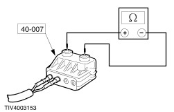
| | | 3 Disconnect Air Bag Sliding Contact C21. | | | 4 Measure the resistance, while turning the steering wheel from lock to lock, between the air bag sliding contact C21 pin 3, circuit 94S - MA8 (VT) and sliding contact C21 pin 1, circuit 91S - MA8 (BK/OG). | | | Is the resistance greater than 2.5-3 ohms (resistance of the simulator)? Yes INSTALL a new air bag sliding contact.
REFER to: Air Bag Sliding Contact.
REACTIVATE the supplemental restraint system. TEST the system for normal operation. No | | C2: CHECK THE DRIVER AIR BAG MODULE RESISTANCE | WARNING:DO NOT UNDER ANY CIRCUMSTANCES PROCEED WITH THIS PINPOINT TEST UNLESS USING WDS. FAILURE TO FOLLOW THIS WARNING MAY RESULT IN PERSONAL INJURY | | | 1 Connect the Test/Deployment lead to the driver air bag module using the appropriate adaptor. | | | 2 Select DMM specific and resistance on WDS. | | | 3 Connect WDS to the Test/Deployment lead. | | | 4 Measure the resistance of the driver air bag module. | | | Is the resistance between 2 and 3 ohms? Yes No INSTALL a new driver air bag module.
REFER to: Driver Air Bag Module.
REACTIVATE the supplemental restraint system. TEST the system for normal operation. | | C3: CHECK THE DRIVER AIR BAG MODULE SQUIB RESISTANCE | | | 1 Connect Air Bag Sliding Contact C21. | | | 2 Disconnect Air Bag Control Module C20. | | | 3 Connect the Breakout Box (BOB) to the air bag control module harness using the appropriate lead and adaptor. | | | 4 Measure the resistance, while turning the steering wheel from lock to lock, between BOB pin 3, circuit 94S - MA8 (VT) and BOB pin 16, circuit 91S - MA8 (BK/OG). | | | Is the resistance between 2.5 - 3 ohms (resistance of the simulator)? Yes VERIFY the customer concern. REACTIVATE the supplemental restraint system. TEST the system for normal operation. No REPAIR circuit 91S-MA8 (BK/OG) or circuit 94S-MA8 (VT). REACTIVATE the supplemental restraint system. TEST the system for normal operation. | | PINPOINT TEST D : WARNING INDICATOR CONDITION TWO FLASHES | WARNING:WAIT AT LEAST ONE MINUTE AFTER DISCONNECTING THE BATTERY GROUND CABLE BEFORE DISCONNECTING ANY SUPPLEMENTAL RESTRAINT SYSTEM ELECTRICAL CONNECTORS. FAILURE TO FOLLOW THIS INSTRUCTION COULD LEAD TO PREMATURE AIR BAG DEPLOYMENT AND MAY RESULT IN PERSONAL INJURY. | WARNING:DO NOT TEST OR WORK ON THE SYSTEM UNLESS ALL THE AIR BAG MODULE AND PRETENSIONER SIMULATORS ARE INSTALLED. DO NOT PROBE THE TERMINALS OF AIR BAG COMPONENTS AS DEPLOYMENT AND PERSONAL INJURY MAY OCCUR. | | TEST CONDITIONS | DETAILS/RESULTS/ACTIONS | | D1: CHECK THE PASSENGER AIR BAG MODULE SQUIB CIRCUIT | | | 1 Deactivate the supplemental restraint system. | | | 2 Disconnect the battery circuit cable.
REFER to: Battery Disconnect (414-01 Battery, Mounting and Cables, General Procedures).
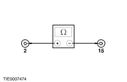
| | | 3 Disconnect Air Bag Control Module C20. | | | 4 Connect the Breakout Box (BOB) to the air bag control module harness using the appropriate lead and adaptor. | | | 5 Measure the resistance between BOB pin 2, circuit 94S - MA11 (VT/WH) and BOB pin 15, circuit 91S - MA11 (BK/WH) harness side. | | | Is the resistance between 2.5 - 3 ohms (resistance of the simulator)? Yes No REPAIR circuit 91S-MA11 (BK/WH) or circuit 94S-MA11 (VT/WH). REACTIVATE the supplemental restraint system. TEST the system for normal operation. | | D2: CHECK THE PASSENGER AIR BAG MODULE SQUIB | WARNING:DO NOT UNDER ANY CIRCUMSTANCES PROCEED WITH THIS PINPOINT TEST UNLESS USING WDS/FDS2000. FAILURE TO FOLLOW THIS INSTRUCTION MAY RESULT IN PERSONAL INJURY. | | | 1 Connect the Test/Deployment lead to the passenger air bag module using the appropriate adaptor. | | | 2 Select DMM specific and resistance on WDS. | | | 3 Connect WDS to the Test Deployment lead. | | | 4 Measure the resistance of the air bag module. | | | Is the resistance between 2 - 3 ohms? Yes VERIFY the customer concern. REACTIVATE the supplemental restraint system. TEST the system for normal operation. No INSTALL a new passenger air bag module.
REFER to: Passenger Air Bag Module.
REACTIVATE the supplemental restraint system. TEST the system for normal operation. | | PINPOINT TEST E : WARNING INDICATOR CONDITION THREE FLASHES | WARNING:WAIT AT LEAST ONE MINUTE AFTER DISCONNECTING THE BATTERY GROUND CABLE BEFORE DISCONNECTING ANY SUPPLEMENTAL RESTRAINT SYSTEM ELECTRICAL CONNECTORS. FAILURE TO FOLLOW THIS INSTRUCTION COULD LEAD TO PREMATURE AIR BAG DEPLOYMENT AND MAY RESULT IN PERSONAL INJURY. | WARNING:DO NOT TEST OR WORK ON THE SYSTEM UNLESS ALL THE AIR BAG MODULE AND PRETENSIONER SIMULATORS ARE INSTALLED. DO NOT PROBE THE TERMINALS OF AIR BAG COMPONENTS AS DEPLOYMENT AND PERSONAL INJURY MAY OCCUR. | | TEST CONDITIONS | DETAILS/RESULTS/ACTIONS | | E1: CHECK FOR A SHORT BETWEEN THE DRIVER AND PASSENGER AIR BAG SQUIB | | | 1 Deactivate the supplemental restraint system. | | | 2 Disconnect the battery circuit cable.
REFER to: Battery Disconnect (414-01 Battery, Mounting and Cables, General Procedures).
| | | 3 Disconnect Air Bag Control Module C20. | | | 4 Connect the Breakout Box (BOB) to the air bag control module harness using the appropriate lead and adaptor. | | | 5 Measure the resistance between: - BOB pin 3, circuit 94S - MA8 (VT) and BOB pin 15, circuit 91S - MA11 (BK/WH); and
- BOB pin 2, circuit 94S - MA11 (VT/WH) and BOB pin 16, circuit 91S - MA8 (BK/OG).
| | | Are the resistances greater than 10,000 ohms? Yes No REPAIR 91S - MA8 (BK/OG); or 91S - MA11 (BK/WH); or 94S - MA8 (VT); or 94S - MA11 (VT/WH). REACTIVATE the supplemental restraint system. TEST the system for normal operation. | | E2: CHECK THE AIR BAG SQUIB CIRCUIT FOR A SHORT TO SUPPLY | | | 1 Measure the resistance between: - BOB pin 2, circuit 94S - MA11 (VT/WH) and BOB pin 19, circuit 94 - MA10 (VT/OG).
- BOB pin 3 circuit 94S - MA8 (VT) and BOB pin 19, circuit 94 - MA10 (VT/OG).
- BOB pin 15, circuit 91S - MA11 (BK/WH) and BOB pin 19, circuit 94 - MA10 (VT/OG).
- BOB pin 16, circuit 91S - MA8 (BK/OG) and BOB pin 19, circuit 94 - MA18 (VT/OG).
| | | Are the resistances greater than 10,000 ohms? Yes No REPAIR circuit 91S - MA8 (BK/OG); or 91S - MA11 (BK/WH); or 94S - MA8 (VT); or 94S - MA11 (VT/WH). REACTIVATE the supplemental restraint system. TEST the system for normal operation. | | E3: CHECK THE AIR BAG SQUIB CIRCUIT FOR A SHORT TO GROUND | | | 1 Measure the resistance between: - BOB pin 2, circuit 94S - MA11 (VT/WH) and BOB pin 20, circuit 91 - MA10B (BK/RD); and BOB pin 25, circuit 91 - MA10C (BK/RD) with passenger and side air bags.
- BOB pin 3, circuit 94S - MA8 (VT) and BOB pin 20, circuit 91 - MA10B (BK/RD); and BOB pin 25, circuit 91 - MA10C (BK/RD) with passenger and side air bags).
- BOB pin 15, circuit 91S - MA11 (BK/WH) and BOB pin 20, circuit 91 - MA10B (BK/RD); and BOB pin 25, circuit 91 - MA10C (BK/RD) with passenger and side air bags.
- BOB pin 16, circuit 91S - MA8 (BK/OG) and BOB pin 20, circuit 91 - MA10B (BK/RD); and BOB pin 25, circuit 91 - MA10C (BK/RD) with passenger and side air bags.
| | | Are the resistances greater than 10,000 ohms? Yes VERIFY the customeer concern. REACTIVATE the supplemental restraint system. TEST the system for normal operation. No REPAIR circuit 91S - MA8 (BK/OG); or 91S - MA11 (BK/WH); or 94S - MA8 (VT); or 94S - MA11 (VT/WH). REACTIVATE the supplemental restraint system. TEST the system for normal operation. | | PINPOINT TEST F : WARNING INDICATOR CONDITION FOUR FLASHES | WARNING:WAIT AT LEAST ONE MINUTE AFTER DISCONNECTING THE BATTERY GROUND CABLE BEFORE DISCONNECTING ANY SUPPLEMENTAL RESTRAINT SYSTEM ELECTRICAL CONNECTORS. FAILURE TO FOLLOW THIS INSTRUCTION COULD LEAD TO PREMATURE AIR BAG DEPLOYMENT AND MAY RESULT IN PERSONAL INJURY. | WARNING:DO NOT TEST OR WORK ON THE SYSTEM UNLESS ALL THE AIR BAG MODULE AND PRETENSIONER SIMULATORS ARE INSTALLED. DO NOT PROBE THE TERMINALS OF AIR BAG COMPONENTS AS DEPLOYMENT AND PERSONAL INJURY MAY OCCUR. | | TEST CONDITIONS | DETAILS/RESULTS/ACTIONS | | F1: CHECK THE SAFETY BELT BUCKLE PRETENSIONER CIRCUIT RESISTANCE | | | 1 Deactivate the supplemental restraint system. | | | 2 Disconnect the battery ground cable.
REFER to: Battery Disconnect (414-01 Battery, Mounting and Cables, General Procedures).
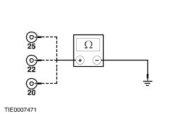
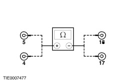
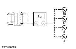
| | | 3 Disconnect Air Bag Control Module C20. | | | 4 Connect the Breakout Box (BOB) to the air bag control module harness using the appropriate lead and adaptor. | | | 5 Measure the resistance between: - Driver side safety belt pretensioner BOB pin 5 (pin 4, RHD), circuit 94S - MA36 (VT/WH), LHD and BOB pin 18 (pin 17, RHD), circuit 91S - MA36 (BK/WH), LHD.
- Passenger side safety belt pretensioner BOB pin 4 (pin 5, RHD), circuit 94S - MA35 (VT/YE), LHD and BOB pin 17 (pin 18, RHD), circuit 91S - MA35 (BK/YE), LHD.
| | | Are the resistances between 2.5 and 3 ohms (resistance of the simulator)? Yes INSTALL a new safety belt buckle and pretensioner.
REFER to: Safety Belt Buckle and Pretensioner.
. REACTIVATE the supplemental restraint system. TEST the system for normal operation. No | | F2: CHECK THE SAFETY BELT BUCKLE PRETENSIONER CIRCUIT FOR A SHORT TO SUPPLY | | | 1 Measure the resistance between: - BOB pin 4, circuit 94S - MA35 (VT/YE), LHD (circuit 94S - MA36 [VT/WH], RHD) and BOB pin 19, circuit 94 - MA10 (VT/OG).
- BOB pin 5, circuit 94S - MA36 (VT/WH), LHD (circuit 94S - MA35 [VT/YE], RHD) and BOB pin 19, circuit 94 - MA10 (VT/OG).
- BOB pin 17, circuit 91S - MA35 (BK/YE), LHD (circuit 91S - MA36 [BK/WH], RHD) and BOB pin 19, circuit 94 - MA10 (VT/OG).
- BOB pin 18, circuit 91S - MA36 (BK/WH), LHD (circuit 91S - MA35 [BK/YE], RHD) and BOB pin 19, circuit 94 - MA10 (VT/OG).
| | | Are the resistance greater than 10,000 ohms? Yes No REPAIR circuit 91S - MA35 (BK/YE); or 91S - MA36 (BK/WH); or 94-MA10 (VT/OG); or 94S - MA35 (VT/YE); or 94S - MA36 (VT/WH). REACTIVATE the supplemental restraint system. TEST the system for normal operation. | | F3: CHECK THE SAFETY BELT BUCKLE PRETENSIONER CIRCUIT FOR A SHORT TO GROUND | | | 1 Measure the resistance between: - BOB pin 4, circuit 94S - MA35 (VT/YE), LHD (circuit 94S - MA36 [VT/WH], RHD) and BOB pin 20, circuit 91 - MA10B (BK/RD) (circuit 91 - MA10 [BK/RD] with passenger air bag); and BOB pin 22, circuit 91 - MA10A (BK/RD) without passenger air bag; and BOB pin 25, circuit 91 - MA10C (BK/RD) with passenger and side air bags.
- BOB pin 5, circuit 94S - MA36 (VT/WH), LHD (circuit 94S - MA35 [VT/YE], RHD) and BOB pin 20, circuit 91 - MA10B (BK/RD) (circuit 91MA10 [BK/RD] with passenger air bag); and BOB pin 22, circuit 91 - MA10A (BK/RD) without passenger air bag; and BOB pin 25, circuit 91 - MA10C (BK/RD) with passenger and side air bags.
- BOB pin 17, circuit 91S - MA35 (BK/WH), LHD (circuit 91S - MA36 [BK/WH], RHD) and BOB pin 20, circuit 91 - MA10B (BK/RD) (circuit 91 - MA10 (BK/RD) with passenger air bag); and BOB pin 22, circuit 91 - MA10A (BK/RD) without passenger air bag; and BOB pin 25, circuit 91 - MA10C (BK/RD) with passenger and side air bags.
- BOB pin 18, circuit 91S - MA36 (BK/WH), LHD (circuit 91S - MA35 [BK/YE], RHD) and BOB pin 20, circuit 91 - MA10B (BK/RD) (circuit 91 - MA10 [BK/RD] with passenger air bag); and BOB pin 22, circuit 91 - MA10A (BK/RD) without passenger air bag; and BOB pin 25, circuit 91 - MA10C (BK/RD) with passenger and side air bags.
| | | Are the resistances greater than 10,000 ohms? Yes No REPAIR circuit 91S - MA35 (BK/YE); or 91S - MA36 (BK/WH); or 91-MA10 (BK/RD); or 94S - MA35 (VT/YE); or 94S - MA36 (VT/WH). REACTIVATE the supplemental restraint system. TEST the system for normal operation. | | F4: CHECK THE SAFETY BELT BUCKLE PRETENSIONER CIRCUIT FOR OPEN CIRCUIT | | | 1 Disconnect Safety Belt Buckle Pretensioner C1880 or C1881. | | | 2 Measure the resistance between: - BOB pin 4, circuit 94S - MA35 (VT/YE), LHD (circuit 94S - MA36 [VT/WH], RHD) and passenger safety belt buckle pretensioner C1880 pin 3, circuit 94S - MA35 (VT/YE), LHD (driver safety belt buckle pretensioner C1881 pin 3, circuit 94S - MA35 [VT/YE], RHD).
- BOB pin 5, circuit 94S - MA36 (VT/WH), LHD (circuit 94S - MA35 [VT/YE], RHD) and driver safety belt buckle pretensioner C1881 pin 3, circuit 94S - MA35 (VT/WH), LHD (passenger safety belt buckle pretensioner C1880 pin 3, circuit 94S - MA35 [VT/YE], RHD).
- BOB pin 17, circuit 91S - MA35 (BK/WH), LHD (circuit 91S - MA36 [BK/WH], RHD) and passenger safety belt buckle pretensioner C1880 pin 1, circuit 91S - MA35 (BK/YE), LHD (driver safety belt buckle pretensioner C1881 pin 1, circuit 94S - MA35 [BK/YE], RHD).
- BOB pin 18, circuit 91S - MA36 (BK/WH), LHD (circuit 91S - MA35 [BK/YE], RHD) and driver safety belt buckle pretensioner C1881 pin 1, circuit 91S - MA35 (BK/YE), LHD (passenger safety belt buckle pretensioner C1880 pin 1, circuit 94S - MA35 [BK/YE], RHD).
| | | Are the resistances less than 5 ohms? Yes INSTALL a new air bag control module.
REFER to: Air Bag Control Module.
REACTIVATE the supplemental restraint system. TEST the system for normal operation. No REPAIR circuit 91S-MA35 (BK/YE); or 91S-MA36 (BK/WH); or 94S-MA35 (VT/YE); or 94S-MA36 (VT/WH). REACTIVATE the supplemental restraint system. TEST the system for normal operation. | | PINPOINT TEST G : DRIVER SIDE AIR BAG HIGH/LOW RESISTANCE OR SHORTED | WARNING:WAIT AT LEAST ONE MINUTE AFTER DISCONNECTING THE BATTERY GROUND CABLE BEFORE DISCONNECTING ANY SUPPLEMENTAL RESTRAINT SYSTEM ELECTRICAL CONNECTORS. FAILURE TO FOLLOW THIS INSTRUCTION COULD LEAD TO PREMATURE AIR BAG DEPLOYMENT AND MAY RESULT IN PERSONAL INJURY. | WARNING:DO NOT TEST OR WORK ON THE SYSTEM UNLESS ALL THE AIR BAG MODULE AND PRETENSIONER SIMULATORS ARE INSTALLED. DO NOT PROBE THE TERMINALS OF AIR BAG COMPONENTS AS DEPLOYMENT AND PERSONAL INJURY MAY OCCUR. | | TEST CONDITIONS | DETAILS/RESULTS/ACTIONS | | G1: CHECK SYSTEM OPERATION | | | 1 Deactivate the supplemental restraint system. | | | 2 Ignition switch in position II. | | | 3 Check the warning light operation. | | | Is the warning light still flashing a fault code? Yes If the fault code is the same, GO to G2. If the fault code has changed, a fault with a lower priority remains. REFER to the Symptom Chart. No | | G2: CHECK DRIVER SIDE AIR BAG CIRCUIT RESISTANCE | | | 1 Ignition switch in position 0. | | | 2 Disconnect the battery ground cable.
REFER to: Battery Disconnect (414-01 Battery, Mounting and Cables, General Procedures).
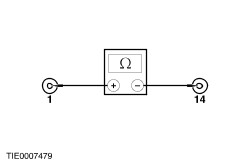
| | | 3 Disconnect Air Bag Control Module C20. | | | 4 Connect the Breakout Box (BOB) to the air bag control module harness using the appropriate lead and adaptor. | | | 5 Measure the resistance between BOB pin 1, circuit 94S - JA37 (VT/BK) and BOB pin 14, circuit 91S - JA37 (BK/GN) harness side. | | | Is the resistance between 2.5 - 3 ohms (resistance of the simulator)? Yes No REPAIR circuit 91S-JA37 (BK/GN) or circuit 94S-JA37 (VT/BK). REACTIVATE the supplemental restraint system. TEST the system for normal operation. | | G3: CHECK CIRCUIT 94S - JA37 AND 91S - JA37 FOR SHORT TO B+ OR GROUND | NOTE:Make sure that the ground location is clean before testing. | | | 1 Disconnect Driver Side Air Bag Module Simulator. | | | 2 Measure the resistance between: - BOB pin 1, circuit 94S - JA37 (VT/BK) and BOB pin 14, circuit 91S - JA37 (BK/GN).
- BOB pin 1, circuit 94S - JA37 (VT/BK) and ground.
- BOB pin 1, circuit 94S - JA37 (VT/BK) and B+.
- BOB pin 14, circuit 91S - JA37 (BK/GN) and ground.
- BOB pin 14, circuit 91S - JA37 (BK/GN) and B+.
| | | Are the resistances greater than 10,000 ohms? Yes INSTALL a new air bag control module.
REFER to: Air Bag Control Module.
REACTIVATE the supplemental restraint system. TEST the system for normal operation. No REPAIR circuit 91S-JA37 (BK/GN) or circuit 94S-JA37 (VT/BK). REACTIVATE the supplemental restraint system. TEST the system for normal operation. | | G4: CHECK THE DRIVER SIDE AIR BAG MODULE RESISTANCE | WARNING:DO NOT UNDER ANY CIRCUMSTANCES PROCEED WITH THIS PINPOINT TEST UNLESS USING WDS. FAILURE TO FOLLOW THIS WARNING MAY CAUSE PERSONAL INJURY. | | | 1 Ignition switch in position 0. | | | 2 Disconnect the battery ground cable.
REFER to: Battery Disconnect (414-01 Battery, Mounting and Cables, General Procedures).
| | | 3 Disconnect Side Air Bag Module Underseat Harness. | | | 4 Select DMM specific and resistance on WDS. | | | 5 Connect the Test/Deployment lead to the side air bag wiring harness connector on the underside of the seat. | | | 6 Connect WDS/FDS2000 to the Test/Deployment lead. | | | 7 Measure the resistance of the air bag module. | | | Is the resistance between 2-3 ohms? Yes VERIFY the customer concern. REACTIVATE the supplemental restraint system. TEST the system for normal operation. No | | G5: CHECK DRIVER SIDE AIR BAG MODULE SEAT HARNESS FOR A SHORT | WARNING:DO NOT UNDER ANY CIRCUMSTANCES PROCEED WITH THIS PINPOINT TEST UNLESS USING WDS. FAILURE TO FOLLOW THIS WARNING MAY CAUSE PERSONAL INJURY. | | | 1 Disassemble the seat to access the side air bag module.
REFER to: Front Seat Backrest /
Front Seat Backrest - 2.5L (200 PS) /
Front Seat Backrest - Vehicles With: Sports Seats.
| | | 2 Disconnect Side Air Bag Module C1964 or C1965. | | | 3 With the Test/Deployment lead still connected, measure the resistance of the wiring harness at connector C1962 pin 1, circuit 94S - JA45 (VT/WH) and C1962 pin 2, circuit 91S - JA45 (BK/WH). | | | Is the resistance greater than 10,000 ohms? Yes No REPAIR circuit 91S-JA45 (BK/WH) or circuit 94S-JA45 (VT/WH). REACTIVATE the supplemental restraint system. TEST the system for normal operation. | | G6: CHECK DRIVER SIDE AIR BAG MODULE SEAT HARNESS FOR OPEN CIRCUIT | | | 1 Measure the resistance of the wiring harness between: - driver side air bag module harness C1962 pin 1, circuit 94S - JA45 (VT/WH) and driver side air bag module harness C1964 (C1965 RHD) pin 1, circuit 94S - JA45 (VT/WH); and
- driver side air bag module harness C1962 pin 2, circuit 91S - JA45 (BK/WH) and driver side air bag harness C1964 (C1965, RHD) pin 2, circuit 91S - JA45 (BK/WH).
| | | Are the resistances less than 0.5 ohms? Yes INSTALL a new side air bag module.
REFER to: Side Air Bag Module.
REACTIVATE the supplemental restraint system. TEST the system for normal operation. No REPAIR circuit 91S-JA45 (BK/WH) or circuit 94S-JA45 (VT/WH). REACTIVATE the supplemental restraint system. TEST the system for normal operation. | | PINPOINT TEST H : PASSENGER SIDE AIR BAG HIGH/LOW RESISTANCE OR SHORTED | WARNING:WAIT AT LEAST ONE MINUTE AFTER DISCONNECTING THE BATTERY GROUND CABLE BEFORE DISCONNECTING ANY SUPPLEMENTAL RESTRAINT SYSTEM ELECTRICAL CONNECTORS. FAILURE TO FOLLOW THIS INSTRUCTION COULD LEAD TO PREMATURE AIR BAG DEPLOYMENT AND MAY RESULT IN PERSONAL INJURY. | WARNING:DO NOT TEST OR WORK ON THE SYSTEM UNLESS ALL THE AIR BAG MODULE AND PRETENSIONER SIMULATORS ARE INSTALLED. DO NOT PROBE THE TERMINALS OF AIR BAG COMPONENTS AS DEPLOYMENT AND PERSONAL INJURY MAY OCCUR. | | TEST CONDITIONS | DETAILS/RESULTS/ACTIONS | | H1: CHECK SYSTEM OPERATION | | | 1 Deactivate the supplemental restraint system. | | | 2 Ignition switch in position II. | | | 3 Check the warning light operation | | | Is the warning light still flashing a fault code? Yes IF the fault code is the same, GO to H2. If the fault code has changed, a fault with a lower priority remains. REFER to the Symptom Chart. No | | H2: CHECK THE PASSENGER SIDE AIR BAG CIRCUIT RESISTANCE | | | 1 Ignition switch in position 0. | | | 2 Disconnect the battery ground cable.
REFER to: Battery Disconnect (414-01 Battery, Mounting and Cables, General Procedures).
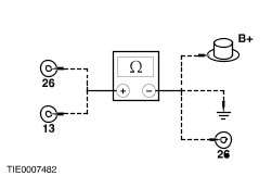
| | | 3 Disconnect Air Bag Control Module C20. | | | 4 Connect the Breakout Box (BOB) to the air bag control module harness using the appropriate lead and adaptor. | | | 5 Measure the resistance between BOB pin 13, circuit 94S - JA38 (VT/OG) and BOB pin 26, circuit 91S - JA38 (BK/RD) harness side. | | | Is the resistance between 2.5 - 3 ohms (resistance of the simulator)? Yes No REPAIR circuit 91S-JA38 (BK/RD) or circuit 94S-JA38 (VT/OG). REACTIVATE the supplemental restraint system. TEST the system for normal operation. | | H3: CHECK CIRCUIT 94S - JA38 (VT/OG) AND 91S - JA38 (BK/RD) FOR A SHORT TO B+ OR GROUND | NOTE:Make sure that the ground location is clean before testing. | | | 1 Disconnect Passenger Side Air Bag Module Simulator. | | | 2 Measure the resistance between: - BOB pin 13, circuit 94S - JA38 (VT/OG) and BOB pin 26, circuit 91S - JA38 (BK/RD).
- BOB pin 13, circuit 94S - JA38 (VT/OG) and ground.
- BOB pin 13, circuit 94S - JA38 (VT/OG) and B+.
- BOB pin 26, circuit 91S - JA38 (BK/RD) and ground.
- BOB pin 26, circuit 91S - JA38 (BK/RD) and B+.
| | | Are the resistances greater than 10,000 ohms? Yes INSTALL a new air bag control module.
REFER to: Air Bag Control Module.
REACTIVATE the supplemental restraint system. TEST the system for normal operation. No REPAIR circuit 91S-JA38 (BK/RD) or circuit 94S-JA38 (VT/OG). REACTIVATE the supplemental restraint system. TEST the system for normal operation. | | H4: CHECK THE PASSENGER SIDE AIR BAG MODULE RESISTANCE | WARNING:DO NOT UNDER ANY CIRCUMSTANCES PROCEED WITH THIS PINPOINT TEST UNLESS USING WDS. FAILURE TO FOLLOW THIS WARNING MAY CAUSE PERSONAL INJURY. | | | 1 Ignition switch in position 0. | | | 2 Disconnect the battery ground cable.
REFER to: Battery Disconnect (414-01 Battery, Mounting and Cables, General Procedures).
| | | 3 Disconnect Side Air Bag Module Underseat Harness. | | | 4 Select DMM specific and resistance on WDS. | | | 5 Connect the Test/Deployment lead to the side air bag wiring harness connector on the under side of the seat. | | | 6 Connect the WDS to the Test/Deployment lead. | | | 7 Measure the resistance of the side air bag module. | | | Is the resistance between 2 - 3 ohms? Yes VERIFY the customer concern. REACTIVATE the supplemental restraint system. TEST the system for normal operation. No | | H5: CHECK PASSENGER SIDE AIR BAG MODULE SEAT HARNESS FOR A SHORT | WARNING:DO NOT UNDER ANY CIRCUMSTANCES PROCEED WITH THIS PINPOINT TEST UNLESS USING WDS. FAILURE TO FOLLOW THIS WARNING MAY CAUSE PERSONAL INJURY. | | | 1 Disassemble the seat to access the side air bag module.
REFER to: Front Seat Backrest /
Front Seat Backrest - 2.5L (200 PS) /
Front Seat Backrest - Vehicles With: Sports Seats.
| | | 2 Disconnect Side Air Bag Module C1964 or C1965. | | | 3 Measure the resistance of the wiring harness between C1963 pin 1, circuit 94S - JA45 (VT/WH) and pin 2, circuit 91S - JA45 (BK/WH). | | | Is the resistance greater than 10,000 ohms? Yes No REPAIR circuit 91S-JA45 (BK/WH) or circuit 94S-JA45 (VT/WH). REACTIVATE the supplemental restraint system. TEST the system for normal operation. | | H6: CHECK PASSENGER SIDE AIR BAG MODULE SEAT HARNESS FOR OPEN CIRCUIT | WARNING:DO NOT UNDER ANY CIRCUMSTANCES PROCEED WITH THIS PINPOINT TEST UNLESS USING WDS. FAILURE TO FOLLOW THIS WARNING MAY CAUSE PERSONAL INJURY. | | | 1 Measure the resistance of the wiring harness between: - passenger side air bag module harness C1963 pin 1, circuit 94S - JA45 (VT/WH) and passenger side air bag module harness C1965 (C1964, RHD) pin 1, circuit 94S - JA45 (VT/WH).
- passenger side air bag module harness C1963 pin 2, circuit 91S - JA45 (BK/WH) and passenger side air bag module harness C1965 (C1964, RHD) pin 2, circuit 94S - JA45 (BK/WH).
| | | Are the resistances less than 0.5 ohms? Yes INSTALL a new side air bag module.
REFER to: Side Air Bag Module.
REACTIVATE the supplemental restraint system. TEST the system for normal operation. No REPAIR circuit 91S-JA45 (BK/WH) or circuit 94S-JA45 (VT/WH). REACTIVATE the supplemental restraint system. TEST the system for normal operation. | | PINPOINT TEST I : DRIVER SIDE IMPACT SENSOR SHORT TO SUPPLY OR GROUND | WARNING:WAIT AT LEAST ONE MINUTE AFTER DISCONNECTING THE BATTERY GROUND CABLE BEFORE DISCONNECTING ANY SUPPLEMENTAL RESTRAINT SYSTEM ELECTRICAL CONNECTORS. FAILURE TO FOLLOW THIS INSTRUCTION COULD LEAD TO PREMATURE AIR BAG DEPLOYMENT AND MAY RESULT IN PERSONAL INJURY. | WARNING:DO NOT TEST OR WORK ON THE SYSTEM UNLESS ALL THE AIR BAG MODULE AND PRETENSIONER SIMULATORS ARE INSTALLED. DO NOT PROBE THE TERMINALS OF AIR BAG COMPONENTS AS DEPLOYMENT AND PERSONAL INJURY MAY OCCUR. | | TEST CONDITIONS | DETAILS/RESULTS/ACTIONS | | I1: CHECK THE DRIVER SIDE IMPACT SENSOR CIRCUIT FOR A SHORT TO SUPPLY OR GROUND. | | | 1 Deactivate the supplemental restraint system. | | | 2 Disconnect the battery ground cable.
REFER to: Battery Disconnect (414-01 Battery, Mounting and Cables, General Procedures).
| | | 3 Disconnect Air Bag Control Module C20. | | | 4 Connect the Breakout Box (BOB) to the air bag control module harness using the appropriate lead and adaptor. | | | 5 Measure the resistance between: - BOB pin 6, circuit 8 - JA39 (WH) and BOB pin 19, circuit 94 - MA10 (VT/OG).
- BOB pin 6, circuit 8 - JA39 (WH) and BOB pin 25, circuit 91 - MA10C (BK/RD); and BOB pin 20, circuit 91 - MA10B (BK/RD).
- BOB pin 7, circuit 9 - JA39 (BN) and BOB pin 19, circuit 94 - MA10 (VT/OG).
- BOB pin 7, circuit 9 - JA39 (BN) and BOB pin 25, circuit 91 - MA10C (BK/RD); and pin 20, circuit 91 - MA10B (BK/RD).
- BOB pin 6, circuit 8 - JA39 (BN) and BOB pin 7, circuit 91 - JA39 (BN).
| | | Are the resistances greater than 10,000 ohms? Yes No REPAIR circuit 8-JA39 (WH); or 9-JA39 (BN); or 91-MA10 (BK/RD); or 94-MA10 (VT/OG). REACTIVATE the supplemental restraint system. TEST the system for normal operation. | | I2: CHECK DRIVER SIDE IMPACT SENSOR CIRCUIT | | | 1 Measure the resistance of the wiring harness between: - BOB pin 6, circuit 8 - JA39 (WH) and side air bag sensor C1960 pin 2, circuit 8 - JA41 (WH) (C1961 pin 2, circuit 8 - JA43 [WH/VT] RHD) harness side.
- BOB pin 7, circuit 9 - JA39 (BN) and side air bag sensor C1960 pin 1, circuit 9 - JA41 (BN) (C1961 circuit 9 - JA43 [BN/WH] RHD) harness side.
| | | Are the resistances less than 0.5 ohms? Yes INSTALL a new impact sensor.
REFER to: Side Impact Sensor.
REACTIVATE the supplemental restraint system. TEST the system for normal operation. No REPAIR circuit 8-JA39 (WH); or 8-JA41 (WH); or 8-JA43 (WH/VT); or 9-JA39 (BN); or 9-JA41 (BN); or 9-JA43 (BN/WH). REACTIVATE the supplemental restraint system. TEST the system for normal operation. | | PINPOINT TEST J : PASSENGER SIDE IMPACT SENSOR SHORT TO SUPPLY OR GROUND | WARNING:WAIT AT LEAST ONE MINUTE AFTER DISCONNECTING THE BATTERY GROUND CABLE BEFORE DISCONNECTING ANY SUPPLEMENTAL RESTRAINT SYSTEM ELECTRICAL CONNECTORS. FAILURE TO FOLLOW THIS INSTRUCTION COULD LEAD TO PREMATURE AIR BAG DEPLOYMENT AND MAY RESULT IN PERSONAL INJURY. | WARNING:DO NOT TEST OR WORK ON THE SYSTEM UNLESS ALL THE AIR BAG MODULE AND PRETENSIONER SIMULATORS ARE INSTALLED. DO NOT PROBE THE TERMINALS OF AIR BAG COMPONENTS AS DEPLOYMENT AND PERSONAL INJURY MAY OCCUR. | | TEST CONDITIONS | DETAILS/RESULTS/ACTIONS | | J1: CHECK THE PASSENGER SIDE IMPACT SENSOR CIRCUIT FOR A SHORT TO SUPPLY OR GROUND | | | 1 Deactivate the supplemental restraint system. | | | 2 Disconnect the battery ground cable.
REFER to: Battery Disconnect (414-01 Battery, Mounting and Cables, General Procedures).
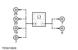
| | | 3 Disconnect Air Bag Control Module C20. | | | 4 Connect the Breakout Box (BOB) to the air bag control module harness using the appropriate lead and adaptor. | | | 5 Measure the resistance between: - BOB pin 8, circuit 8 - JA40 (WH/VT)and BOB pin 19, circuit 94 - MA10 (VT/OG).
- BOB pin 8, circuit 8 - JA40 (WH/VT) and BOB pin 20, circuit 91 - MA10B (BK/RD); and BOB pin 25, circuit 91 - MA10C (BK/RD).
- BOB pin 9, circuit 9 - JA40 (BN/WH) and BOB pin 19, circuit 94 - MA10 (VT/OG).
- BOB pin 9, circuit 9 - JA40 (BN/WH) and BOB pin 20, circuit 91 - MA10B (BK/RD); and BOB pin 25, circuit 91 - MA10C (BK/RD).
- BOB pin 8, circuit 8 - JA40 (WH/VT) and BOB pin 9, circuit 9 - JA40 (BN/WH).
| | | Are the resistances greater than 10,000 ohms? Yes No REPAIR circuit 8-JA40 (WH/VT); or 9-JA40 (BN/WH); or 91-MA10 (BK/RD). REACTIVATE the supplemental restraint system. TEST The system for normal operation. | | J2: CHECK THE PASSENGER SIDE IMPACT SENSOR CIRCUIT | | | 1 Measure the resistance of the wiring harness between: - BOB pin 8, circuit 8 - JA40 (WH/VT) and side air bag sensor C1961 pin 2, circuit 8 - JA43 (WH/VT) (C1960 pin 2, circuit 8 - JA41 [WH] RHD) harness side.
- BOB pin 9, circuit 9 - JA40 (BN/WH) and side air bag sensor C1961 pin 1, circuit 9 - JA43 (BN/WH) (C1960 pin 1, circuit 9 - JA41 [BN] RHD) harness side.
| | | Are the resistances less than 0.5 ohms? Yes INSTALL a new impact sensor.
REFER to: Side Impact Sensor.
REACTIVATE the supplemental restraint system. TEST the system for normal operation. No REPAIR circuit 8-JA40 (WH/VT); or 8-JA41 (WH); or 8-JA43 (WH/VT); or 9-JA40 (BN/WH); or 9-JA41 (BN) or 9-JA43 (BN/WH). REACTIVATE the supplemental restraint system. TEST the system for normal operation. | |