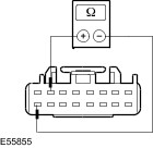
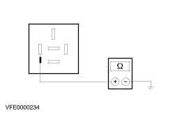
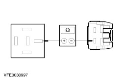
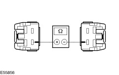
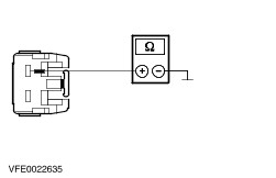
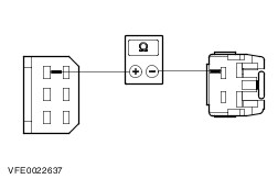
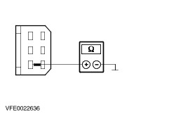
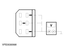
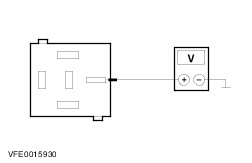
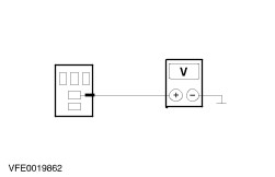
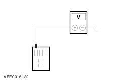
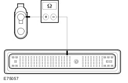
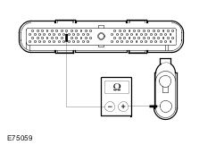
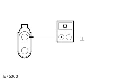
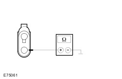
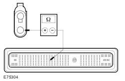
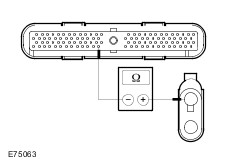
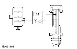
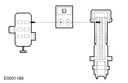
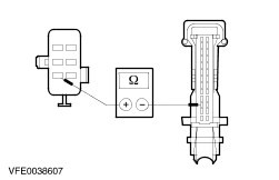
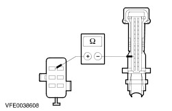
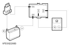
| Diagnosis and Testing Refer to Wiring Diagrams Section 412-00, for schematic and connector information. Special Tool(s) | | Terminal Probe Kit 418-S035 | General Equipment Digital Multimeter (compatible with K-type thermocouple) Thermometer - Fluke 80 PK-8 (FSE number 260 4102 001 07) R-134a refrigerant centre or set of R134a pressure gauges Worldwide Diagnostic System (WDS) Inspection and Checking - Visually CHECK for any obvious mechanical or electrical damage.
Visual Inspection | Mechanical | Electrical | - Drive belt
- Coolant level
- Refrigerant lines
- Condenser
- Compressor
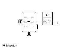
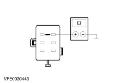
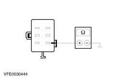
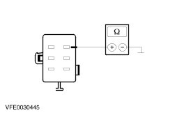
| - Fuses
- Wiring harness
- Connectors
| - RECTIFY any obvious causes for a concern found during the visual inspection before performing any further tests. CHECK the operation of the system.
- If the concern persists after the visual inspection, use WDS to PERFORM a fault diagnosis of the climate control system and electronic engine management, and RESOLVE the fault(s) displayed according to the fault description. CHECK the operation of the system.
- If the concern persists after the visual inspection, PROCEED as indicated on the symptom chart.
- Following the checking or elimination of the fault and after completion of operations, the fault memories of all the modules of the vehicle must be READ OUT and any stored faults must be DELETED. READ OUT all fault memories again following a road test.
Refrigerant Circuit - Quick Check WARNING:The air conditioning system is filled with refrigerant R134a. Observe "Health and Safety Precautions". For further information
REFER to: Health and Safety Precautions (100-00 General Information, Description and Operation).
Refrigerant circuit check WARNING:Under certain circumstances, refrigerant lines and A/C components may be extremely hot or cold. Exercising care, touch the refrigerant lines or A/C components in order to check this. Failure to observe this instruction can lead to injury. - The refrigerant line from the refrigerant compressor to the condenser must be hot.
- The refrigerant line from the condenser to the fixed orifice tube must be warm, but it should be cooler than the refrigerant line mentioned above.
- Determine the difference in temperature upstream and downstream of the condenser by measuring the temperatures. Depending on the ambient temperature, the temperature difference should be more than 20°C. If the temperature difference is less, check the condenser for contamination or damage to the fins as well as operation of the radiator fan.
- The refrigerant line between the fixed orifice tube and the evaporator must be cold from the installation position of the fixed orifice tube. Depending on the weather, the refrigerant line may also be iced up on the outside.
- The refrigerant line between the evaporator and the A/C compressor including the suction accumulator must be cold.
Evaporator outlet line temperature test To test the power of the A/C system, the temperature of the evaporator outlet line must be measured. The following preparations need to be made to do this: - Open all windows.
- Set the air distribution to the defrost/dashboard position and open all the ventilation nozzles.
- DO NOT switch on recirculated air.
- Select lowest blower switch setting.
- Select lowest temperature setting.
NOTE:The temperature measurement cannot be performed using a non-contact thermometer. Incorrect readings can result from surface reflections. Connect the temperature sensor (Fluke 80 PK-8) to the evaporator outlet line. Locate the temperature sensor as close as possible to the evaporator. Connect the temperature sensor to the multimeter. Start the engine and allow it to run at idle speed for several minutes. Switch on the air-conditioning system. After three minutes, measure the surface temperature of the evaporator outlet line. If the temperature measured is 4°C or lower, the A/C system is OK. If the temperature is higher, the A/C system may be under-filled. For further information
REFER to: Air Conditioning (A/C) System Recovery, Evacuation and Charging (412-00 Climate Control System - General Information, General Procedures).
Frequent faults and their causes If there is a concern over inadequate air conditioning performance, make sure that the temperature control flap is operating correctly. - No or poor cooling performance:
- Blockage or narrowing of a refrigerant line or in the suction accumulator: The location of the blockage or narrowing can easily be located by temperature comparisons at the refrigerant lines and the suction accumulator. The blockage or restriction is located at the point where the temperature difference is identified. Note: A temperature difference in the area of the fixed orifice tube is normal. Once the location of the blockage or restriction has been detected, check the relevant component and renew if necessary. - Sudden poor cooling performance (after the air conditioning has been switched off for approx. 5 minutes, the cooling performance returns to normal):
- Cause is an iced-up fixed orifice tube caused by moisture in the refrigerant circuit. In order to ensure that moisture is completely removed from the refrigerant circuit, the suction accumulator must be renewed and the evacuation time must be extended to 2-3 hours. For further information, REFER to: Suction Accumulator (412-03 Air Conditioning, Removal and Installation), Air Conditioning (A/C) System Recovery, Evacuation and Charging (412-00 Climate Control System - General Information, General Procedures). Fault memory interrogation without WDS - vehicles with electronic automatic temperature control (EATC) and vehicles built from 06/2003 NOTE:For vehicles built from 06/2003, fault memory interrogation is also possible via the climate control assembly in the case of automatic temperature control (ATC). NOTE:NOTE: On vehicles equipped with a DVD navigation system with touchscreen, interrogation of the fault memory is only possible using WDS. The climate control system features a self-diagnosis function which can detect and store both current permanent faults as well as intermittent faults which have occurred during normal operation of the vehicle. It is also possible to read out these faults via the display of the (E)ATC module. To start self-diagnosis or to read out the fault memory, the ignition key must be turned to the "ON" position and the battery voltage must be between 9 V and 16 V. Activation of self-diagnosis On the (E)ATC module, PRESS the "OFF" and "FOOTWELL" buttons simultaneously for at least 2 seconds, then PRESS "AUTO" within 1.5 seconds. The self-diagnosis which then starts lasts a few seconds. An animated display will appear during this time in the (E)ATC display. Any faults found are displayed in the form of trouble codes. Example: first of all, "93" flashes for 2 seconds, then "42" flashes for 2 seconds - DTC 9342 = internal control unit fault. If no faults are stored, then all of the segments in the display are actuated. The following table gives information on the possible DTCs and their corresponding meanings. By PRESSING the "DEFROST" button, the fault memory is cleared and diagnosis mode is ended. To end the diagnostic mode without clearing the DTCs, PRESS any other (E)ATC button. Read out stored faults On the (E)ATC module, PRESS the "OFF" and "FOOTWELL" buttons simultaneously for at least 2 seconds, then PRESS "HEADROOM" within 1.5 seconds. Any stored intermittent faults are output on the (E)ATC display and should be written down for safety. By PRESSING the "DEFROST" button, the fault memory is cleared and diagnosis mode is ended. To end the diagnostic mode without clearing the DTCs, PRESS any other button on the (E)ATC module. Reading out the (E)ATC software version On the (E)ATC module, PRESS the "OFF" and "FOOTWELL" buttons simultaneously for at least 2 seconds, then PRESS "A/C" within 1.5 seconds. The SW version is output on the (E)ATC display. The output mode is ended by PRESSING any button. Update the software version For vehicles up to 06/2003, it is possible to update the software of the EATC and of the ATC via the WDS. For this purpose it must be ensured that the WDS is equipped with the latest WDS software. Fault Code Table | Self-test code | Description | Action | | B1200 / 9200 | Internal control module fault | CLEAR fault memory. If the fault occurs again after a functional test, RENEW the (E)ATC module. | | B1242 / 9242 | Fault in the circuit of the air recirculation flap actuator | GO to Pinpoint Test D. | | B1251 / 9251 1 | Break in circuit for interior temperature sensor | GO to Pinpoint Test M. | | B1253 / 9253 1 | Short in circuit for interior temperature sensor (short to ground) | GO to Pinpoint Test M. | | B1261 / 9261 1 | Short circuit in sun load sensor circuit (short to ground) | GO to Pinpoint Test L. | | B1262 / 9262 | Fault in circuit of air flap actuator for defroster/center vents flap | GO to Pinpoint Test E. | | B1263 / 9263 | Circuit of actuator for air distribution flap faulty | GO to Pinpoint Test F. | | B1342 / 9342 | Internal control module fault | CLEAR fault memory. If the fault occurs again after a functional test, RENEW the (E)ATC module. | | B1676 / 9676 | Power supply voltage outside tolerance | CHECK charging system. For further information
REFER to: Charging System (414-00 Charging System - General Information, Diagnosis and Testing).
If the charging system is OK, GO to Pinpoint Test J. | | B2266 / A266 | Circuit of temperature control flap actuator faulty | GO to Pinpoint Test G. | | B2297 / A299 | Break in circuit for footwell air outlet temperature sensor | GO to Pinpoint Test H. | | B2298 / A307 | Short in circuit for footwell air outlet temperature sensor (short to ground) | GO to Pinpoint Test H. | | A297 2 | Break in circuit for center vents air outlet temperature sensor | GO to Pinpoint Test I. | | A298 2 | Short in circuit for center vents air outlet temperature sensor (short to ground) | GO to Pinpoint Test I. | | B2308 / A308 1 | Fault in the circuit of the interior temperature sensor blower | GO to Pinpoint Test N. | | B2516 / A516 3 | Circuit of blower control faulty | GO to Pinpoint Test K. | 1 Not on vehicles with manual temperature control 2 Vehicles built from 06/2003 3 Not on vehicles with manual temperature control built before 06/2003 Symptom Chart Symptom Chart | Symptom | Possible Sources | Action | | Blower motor inoperative / partly inoperative - vehicles without electronic automatic temperature control (EATC) built up to 06/2003 | * Fuse(s) * Circuit(s) * Blower relay * Blower motor * Blower switch * Blower resistor assembly | * | | Blower permanently on - vehicles without electronic automatic temperature control (EATC) built up to 06/2003 | * Blower switch * Circuit(s) * Blower relay | * | | Air conditioning inoperative (blower function OK) | * Fuse(s) * Circuit(s) * Electronic automatic temperature control (EATC) module or automatic temperature control (ATC) module * A/C clutch diode * A/C clutch * A/C clutch relay * Refrigerant quantity / circuit * Refrigerant low-pressure switch * Refrigerant high-pressure switch * Powertrain control module (PCM) | * | | Inadequate cooling power from the air conditioning (A/C clutch function OK) | * Radiator fan malfunction * Refrigerant quantity * Refrigerant circuit | * Perform the Refrigerant Circuit Quick Check. * PERFORM a fault diagnosis on the powertrain control module (PCM) with WDS. * CHECK the refrigerant quantity/circuit with the R134a refrigerant centre and REPAIR the system as required. | | Malfunction of the recirculated air flap | * Circuit(s) * Air recirculation flap * Air recirculation flap actuator * Electronic automatic temperature control (EATC) module or automatic temperature control (ATC) module | * | | Defrost/center vents air flap malfunction | * Circuit(s) * Defrost/center vents air flap * Defrost/center vents air flap actuator | * | | Malfunction of the air distribution flap | * Circuit(s) * Air distribution flap * Actuator – air distribution flap | * | | Temperature control flap malfunction | * Circuit(s) * Temperature control flap * Temperature control flap actuator | * | | Fault in circuit for footwell air outlet temperature sensor | * Circuit(s) * Air outlet temperature sensor, footwell | * | | Circuit of center vents air outlet temperature sensor faulty - vehicles built from 06/2003 | * Circuit(s) * Air outlet temperature sensor, centre nozzles | * | | Electronic automatic temperature control (EATC) module or automatic temperature control (ETC) module inoperative (no display in the climate control assembly) | * Fuse(s) * Circuit(s) * Central junction box (CJB) * Blower relay * Electronic automatic temperature control (EATC) module or automatic temperature control (ATC) module | * | | Blower malfunction - vehicles with electronic automatic temperature control (EATC) and vehicles built from 06/2003 (display in climate control assembly OK) | * Circuit(s) * Electronic automatic temperature control (EATC) module or automatic temperature control (ATC) module * Blower control module | * | | Sun load sensor circuit faulty - vehicles with electronic automatic temperature control (EATC) | * Circuit(s) * Sun load sensor | * | | Interior temperature sensor circuit faulty - vehicles with electronic automatic temperature control (EATC) | * Circuit(s) * Interior temperature sensor | * | | Interior temperature sensor blower circuit faulty - vehicles with electronic automatic temperature control (EATC) | * Fuse * Circuit(s) * Interior temperature sensor | * | System Checks | PINPOINT TEST A : BLOWER MOTOR INOPERATIVE / PARTLY INOPERATIVE - VEHICLES WITHOUT ELECTRONIC AUTOMATIC TEMPERATURE CONTROL (EATC) BUILT UP TO 06/2003 | | TEST CONDITIONS | DETAILS/RESULTS/ACTIONS | | A1: CHECK ALL SPEED SETTINGS OF THE BLOWER MOTOR | | | 1 Ignition switch in position II. | | | 2 Switch the blower switch through all speed settings. | | | Is the blower motor inoperative in all speed settings? Yes No - The blower motor is only inoperative in switch position 4: GO to A17. - The blower motor is inoperative in switch positions 1, 2 and/or 3: GO to A18. | | A2: CHECK FUSE F6 | | | 1 Ignition switch in position 0. | | | 2 CHECK fuse F6 (BJB). | | | Is the fuse OK? Yes No RENEW fuse F6 (40 A). CHECK the operation of the system. If the fuse blows again, LOCATE and REPAIR the short using the Wiring Diagrams. | | A3: CHECK THE VOLTAGE AT FUSE F6 | | | 1 Connect fuse F6 (BJB). | | | 2 Measure the voltage between fuse F6 (40 A) and ground. | | | Does the meter display battery voltage? Yes No REPAIR the voltage supply to fuse F6 using the Wiring Diagrams. CHECK the operation of the system. | | A4: CHECK FUSE F93 | | | 1 CHECK fuse F93 (CJB). | | | Is the fuse OK? Yes No RENEW fuse F93 (10 A). CHECK the operation of the system. If the fuse blows again, LOCATE and REPAIR the short using the Wiring Diagrams. | | A5: CHECK THE VOLTAGE AT FUSE F93 | | | 1 Connect fuse F93 (CJB). | | | 2 Ignition switch in position II. | | | 3 Measure the voltage between fuse F93 (10 A) and ground. | | | Does the meter display battery voltage? Yes No REPAIR the voltage supply to fuse F93 using the Wiring Diagrams. CHECK the operation of the system. | | A6: CHECK THE VOLTAGE AT THE BLOWER MOTOR | | | 1 Ignition switch in position 0. | | | 2 Disconnect Connector C442 from heater blower motor. | | | 3 Ignition switch in position II. | | | 4 Measure the voltage between the blower motor, connector C442, pin 1, circuit 15S-FA45 (GN/RD), wiring harness side and ground. | | | Does the meter display battery voltage? Yes No | | A7: CHECK THE VOLTAGE AT THE BLOWER RELAY | | | 1 Ignition switch in position 0. | | | 2 Disconnect Blower relay from socket C920 (CJB). | | | 3 Measure the voltage between the blower relay, socket C920, pin 5, wiring harness side and ground. | | | Does the meter display battery voltage? Yes No | | A8: CHECK THE CIRCUIT BETWEEN THE CJB AND THE BJB FOR OPEN CIRCUIT | | | 1 Disconnect Fuse F6 (BJB). | | | 2 Disconnect Connector C504 from CJB. | | | 3 Measure the resistance between the BJB, fuse F6, circuit 30S-FA24 (RD), wiring harness side and the CJB, connector C504, pin 1, circuit 30-FA24 (RD), wiring harness side. | | | Is a resistance of less than 2 Ohm registered? Yes CHECK the CJB and RENEW as necessary. CHECK the operation of the system. No LOCATE and REPAIR the break in circuit 30-FA24 (RD) between the CJB and fuse F6 using the Wiring Diagrams. CHECK the operation of the system. | | A9: CHECK THE CONTROL VOLTAGE AT THE BLOWER RELAY | | | 1 Ignition switch in position II. | | | 2 Measure the voltage between the blower relay, socket C920, pin 2, wiring harness side and ground. | | | Does the meter display battery voltage? Yes No | | A10: CHECK THE CIRCUIT AT THE CJB FOR DAMAGE | | | 1 Disconnect Connector C502 from CJB. | | | 2 Measure the resistance between the CJB, connector C502, pin 7, circuit 15-FA23 (GN/BU), wiring harness side and the CJB, connector C502, pin 16, circuit 15-FA23 (GN/BU), wiring harness side. | | | Is a resistance of less than 2 Ohm registered? Yes CHECK the CJB and RENEW as necessary. CHECK the operation of the system. No LOCATE and REPAIR the break in circuit 15-FA23 (GN/BU) at the CJB using the Wiring Diagrams. CHECK the operation of the system. | | A11: CHECK THE GROUND CONNECTION OF THE BLOWER RELAY | | | 1 Ignition switch in position 0. | | | 2 Measure the resistance between the blower relay, socket C920, pin 1, wiring harness side and ground. | | | Is a resistance of less than 2 Ohm registered? Yes No RENEW the CJB. CHECK the operation of the system. | | A12: CHECK THE CIRCUIT BETWEEN THE BLOWER RELAY AND THE BLOWER MOTOR FOR OPEN CIRCUIT | | | 1 Measure the resistance between the blower relay, socket C920, pin 3, wiring harness side and the blower motor, connector C442, pin 1, circuit 15S-FA45 (GN/RD), wiring harness side. | | | Is a resistance of less than 2 Ohm registered? Yes RENEW the blower relay. CHECK the operation of the system. No | | A13: CHECK THE CIRCUIT BETWEEN THE CJB AND THE BLOWER MOTOR FOR OPEN CIRCUIT | | | 1 Disconnect Connector C503 from CJB. | | | 2 Measure the resistance between the CJB, connector C503, pin 2, circuit 15S-FA45 (GN/RD), wiring harness side and the blower motor, connector C442, pin 1, circuit 15S-FA45 (GN/RD), wiring harness side. | | | Is a resistance of less than 2 Ohm registered? Yes CHECK the CJB and RENEW as necessary. CHECK the operation of the system. No LOCATE and RECTIFY the open circuit in circuit 15S-FA45 (GN/RD) between the CJB and the blower motor with the aid of the Wiring Diagrams. CHECK the operation of the system. | | A14: CHECK THE GROUND CONNECTION OF THE BLOWER MOTOR | | | 1 Ignition switch in position 0. | | | 2 Set the blower switch to "MAXIMUM". | | | 3 Measure the resistance between the blower motor, connector C442, pin 2, circuit 31S-FA45 (BK/OG), wiring harness side and ground. | | | Is a resistance of less than 2 Ohm registered? Yes RENEW the blower motor. CHECK the operation of the system. No | | A15: CHECK THE CIRCUIT BETWEEN THE BLOWER MOTOR AND THE BLOWER SWITCH FOR OPEN CIRCUIT | | | 1 Disconnect Connector C448 from blower switch. | | | 2 Measure the resistance between the blower motor, connector C442, pin 2, circuit 31S-FA45 (BK/OG), wiring harness side and the blower switch, connector C448, pin 1, circuit 31S-FA33 (BK/OG), wiring harness side. | | | Is a resistance of less than 2 Ohm registered? Yes No LOCATE and RECTIFY the open circuit in circuit 31S-FA45 (BK/OG) between the blower motor and soldered connection S113 using the Wiring Diagrams. CHECK the operation of the system. | | A16: CHECK THE GROUND CONNECTION OF THE BLOWER SWITCH | | | 1 Measure the resistance between the blower switch, connector C448, pin 3, circuit 31-FA1 (BK), wiring harness side and ground. | | | Is a resistance of less than 2 Ohm registered? Yes INSTALL A NEW blower switch. CHECK the operation of the system. No LOCATE and RECTIFY the open circuit in circuit 31-FA1 (BK) between the blower switch and ground connection G204 using the Wiring Diagrams. CHECK the operation of the system. | | A17: CHECK THE CIRCUIT BETWEEN THE BLOWER MOTOR AND THE BLOWER SWITCH FOR OPEN CIRCUIT | | | 1 Ignition switch in position 0. | | | 2 Disconnect Connector C448 from blower switch. | | | 3 Disconnect Connector C442 from blower motor. | | | 4 Measure the resistance between the blower motor, connector C442, pin 2, circuit 31S-FA45 (BK/OG), wiring harness side and the blower switch, connector C448, pin 1, circuit 31S-FA33 (BK/OG), wiring harness side. | | | Is a resistance of less than 2 Ohm registered? Yes INSTALL A NEW blower switch. CHECK the operation of the system. No LOCATE and RECTIFY the open circuit in circuit 31S-FA33 (BK/OG) between soldered connection S113 and the blower switch with the aid of the Wiring Diagrams. CHECK the operation of the system. | | A18: CHECK THE BLOWER SWITCH | | | 1 Ignition switch in position 0. | | | 2 Disconnect Connector C448 from blower switch. | | | 3 Ignition switch in position II. | | | 4 Measure the voltage between the blower switch, connector C448, pin 6, circuit 31S-FA32 (BK/BU), wiring harness side and ground. | | | 5 Measure the voltage between the blower switch, connector C448, pin 2, circuit 31S-FA31 (BK/YE), wiring harness side and ground. | | | 6 Measure the voltage between the blower switch, connector C448, pin 4, circuit 31S-FA30 (BK/WH), wiring harness side and ground. | | | Is battery voltage measured in all cases? Yes INSTALL A NEW blower switch. CHECK the operation of the system. No - Battery voltage not measured in any case: GO to A19. - Battery voltage not measured in one/two cases: GO to A20. | | A19: CHECK THE VOLTAGE AT THE BLOWER RESISTOR | | | 1 Ignition switch in position 0. | | | 2 Disconnect Connector C443 from blower resistor. | | | 3 Ignition switch in position II. | | | 4 Measure the voltage between the blower resistor, connector C443, pin 1, circuit 31S-FA19 (BK/WH), wiring harness side and ground. | | | Does the meter display battery voltage? Yes RENEW the blower resistor. CHECK the operation of the system. No LOCATE and REPAIR the break in circuit 31S-FA19 (BK/WH) between soldered connection S113 and the blower resistor using the Wiring Diagrams. CHECK the operation of the system. | | A20: CHECK THE CIRCUIT BETWEEN THE BLOWER RESISTOR AND THE BLOWER SWITCH FOR OPEN CIRCUIT | | | 1 Ignition switch in position 0. | | | 2 Disconnect Connector C443 from blower resistor. | | | 3 Measure the resistance between the blower resistor, connector C443, pin 4, circuit 31S-FA32 (BK/BU), wiring harness side and the blower switch, connector C448, pin 6, circuit 31S-FA32 (BK/BU), wiring harness side. | | | Is a resistance of less than 2 Ohm registered? Yes No LOCATE and REPAIR the break in circuit 31S-FA32 (BK/BU) between the blower resistor and the blower switch using the Wiring Diagrams. CHECK the operation of the system. | | A21: CHECK THE CIRCUIT BETWEEN THE BLOWER RESISTOR AND THE BLOWER SWITCH FOR OPEN CIRCUIT | | | 1 Measure the resistance between the blower resistor, connector C443, pin 2, circuit 31S-FA31 (BK/YE), wiring harness side and the blower switch, connector C448, pin 2, circuit 31S-FA31 (BK/YE), wiring harness side. | | | Is a resistance of less than 2 Ohm registered? Yes No LOCATE and REPAIR the break in circuit 31S-FA31 (BK/YE) between the blower resistor and the blower switch using the Wiring Diagrams. CHECK the operation of the system. | | A22: CHECK THE CIRCUIT BETWEEN THE BLOWER RESISTOR AND THE BLOWER SWITCH FOR OPEN CIRCUIT | | | 1 Measure the resistance between the blower resistor, connector C443, pin 3, circuit 31S-FA30 (BK/WH), wiring harness side and the blower switch, connector C448, pin 4, circuit 31S-FA30 (BK/WH), wiring harness side. | | | Is a resistance of less than 2 Ohm registered? Yes RENEW the blower resistor. CHECK the operation of the system. No LOCATE and REPAIR the break in circuit 31S-FA30 (BK/WH) between the blower resistor and the blower switch using the Wiring Diagrams. CHECK the operation of the system. | | PINPOINT TEST B : BLOWER PERMANENTLY ON - VEHICLES WITHOUT ELECTRONIC AUTOMATIC TEMPERATURE CONTROL (EATC) BUILT UP TO 06/2003 | | TEST CONDITIONS | DETAILS/RESULTS/ACTIONS | | B1: CHECK FAULT CONDITIONS | | | 1 Ignition switch in position 0. | | | 2 Set the blower switch to "LEVEL 1". | | | Does the blower motor run? Yes No The blower motor only runs with the ignition in the "ON" position: GO to B2. | | B2: CHECK THE BLOWER SWITCH | | | 1 Disconnect Connector C448 from blower switch. | | | 2 Ignition switch in position II. | | | Does the blower motor run? Yes No INSTALL A NEW blower switch. CHECK the operation of the system. | | B3: CHECK THE CIRCUITS BETWEEN THE BLOWER RESISTOR AND THE BLOWER SWITCH FOR SHORT CIRCUIT | | | 1 Ignition switch in position 0. | | | 2 Disconnect Connector C443 from blower resistor. | | | 3 Ignition switch in position II. | | | Does the blower motor run continuously? Yes CHECK all circuits that are connected to soldered connection S113 for a short circuit with the aid of the Wiring Diagrams and RECTIFY any short circuit(s) found. CHECK the operation of the system. No CHECK all circuits between the blower resistor and the blower switch for a short circuit using the Wiring Diagrams and RECTIFY any short circuit(s) found. CHECK the operation of the system. | | B4: CHECK THE CONTROL VOLTAGE AT THE BLOWER RELAY | | | 1 Disconnect Blower relay from socket C920 (CJB). | | | 2 Measure the voltage between the blower relay, socket C920, pin 2, wiring harness side and ground. | | | Is a voltage measured? Yes LOCATE and RECTIFY the short to voltage supply in the circuits connected to fuse F93 using the Wiring Diagrams. CHECK the operation of the system. No | | B5: TEST THE VOLTAGE AT THE BLOWER RELAY | | | 1 Measure the voltage between the blower relay, socket C920, pin 3, wiring harness side and ground. | | | Is a voltage measured? Yes LOCATE and REPAIR the short to voltage in the circuits between the blower relay and the blower motor using the Wiring Diagrams. CHECK the operation of the system. No RENEW the blower relay. CHECK the operation of the system. | | PINPOINT TEST C : AIR CONDITIONING INOPERATIVE (BLOWER FUNCTION OK) | | TEST CONDITIONS | DETAILS/RESULTS/ACTIONS | | C1: CHECK PLAUSIBILITY OF AMBIENT TEMPERATURE | | | 1 Ignition switch in position 0. | | | 2 Connect the diagnostic tool. | | | 3 Using the diagnostic tester, select the PCM and check the ambient temperature in the Data Logger. | | | Is the indicated ambient temperature plausible? Yes No | | C2: CHECK THE A/C REQUEST SIGNAL IN THE POWERTRAIN CONTROL MODULE (PCM) | | | 1 Switch on the blower. | | | 2 Switch on the air-conditioning system. | | | 3 Select lowest temperature setting. | | | 4 Check whether an A/C request signal is displayed in the WDS data logger. | | | Is an A/C request signal displayed in the data logger of the PCM? Yes No | | C3: READ OUT THE FAULT MEMORY OF THE (E)ATC MODULE | | | 1 Use WDS to select the (E)ATC module and read out the fault memory. | | | Is it possible to establish communications with the (E)ATC module? Yes RESOLVE the fault(s) displayed according to the fault description. CHECK the operation of the system. If no faults are displayed, RENEW the (E)ATC module. No REFER to: Communications Network (418-00 Module Communications Network, Diagnosis and Testing). | | C4: CHECK FUSE F31 | | | 1 Ignition switch in position 0. | | | 2 CHECK fuse F31 (BJB). | | | Is the fuse OK? Yes No RENEW fuse F31 (7.5 A). If the fuse blows again after switching on the air conditioning, CHECK the A/C clutch diode (BJB) and RENEW as necessary. If the A/C clutch diode is OK, LOCATE and RECTIFY the short with the aid of the Wiring Diagrams. CHECK the operation of the system. | | C5: CHECK THE VOLTAGE AT FUSE F31 | | | 1 Connect fuse F31 (BJB). | | | 2 Measure the voltage between fuse F31 (7.5 A) and ground. | | | Does the meter display battery voltage? Yes No REPAIR the voltage supply to fuse F31 using the Wiring Diagrams. CHECK the operation of the system. | | C6: CHECK FUSE F82 | | | 1 CHECK fuse F82 (CJB). | | | Is the fuse OK? Yes No RENEW fuse F82 (7.5 A). If the fuse blows again, LOCATE and REPAIR the short using the Wiring Diagrams. CHECK the operation of the system. | | C7: CHECK THE VOLTAGE AT FUSE F82 | | | 1 Connect fuse F82 (CJB). | | | 2 Ignition switch in position II. | | | 3 Measure the voltage between fuse F82 (7.5 A) and ground. | | | Does the meter display battery voltage? Yes No REPAIR the voltage supply to fuse F82 using the Wiring Diagrams. CHECK the operation of the system. | | C8: CHECK THE VOLTAGE SUPPLY TO THE A/C CLUTCH RELAY | | | 1 Ignition switch in position 0. | | | 2 Disconnect A/C clutch relay socket C906 (BJB). | | | 3 Measure the voltage between the air conditioning clutch relay, socket C906, pin 5, circuit 30-FA12 (GN/BU) (vehicles built from 08/2003: RD), wiring harness side and ground. | | | Does the meter display battery voltage? Yes No LOCATE and RECTIFY the break in circuit 30-FA12 (GN/BU) (vehicles built from 08/2003: RD) between fuse F31 and the air conditioning clutch relay with the aid of the Wiring Diagrams. CHECK the operation of the system. | | C9: CHECK THE CONTROL VOLTAGE AT THE A/C CLUTCH RELAY | | | 1 Ignition switch in position II. | | | 2 Measure the voltage between the air conditioning clutch relay, socket C906, pin 2, circuit 15-FA11 (GN/YE), wiring harness side and ground. | | | Does the meter display battery voltage? Yes No LOCATE and RECTIFY the open circuit in circuit 15-FA11 (GN/YE) between soldered connection S437 and the A/C clutch relay using the Wiring Diagrams. CHECK the operation of the system. | | C10: CHECK THE CIRCUIT OF THE A/C CLUTCH | | | 1 Ignition switch in position 0. | | | 2 Use a fused test cable (7.5 A) to bridge the air conditioning clutch relay, socket C906, pin 3 and pin 5, wiring harness side. | | | 3 Check the operation of the air conditioning clutch. | | | Does the air conditioning clutch work? Yes No | | C11: CHECK THE CIRCUIT BETWEEN THE A/C CLUTCH RELAY AND THE A/C CLUTCH FOR OPEN CIRCUIT | | | 1 Disconnect Connector C101 from A/C clutch (vehicles with diesel engine: connector C104). | | | 2 Measure the resistance between the A/C clutch relay, socket C906, pin 3, circuit 15S-FA12 (RD/BU), wiring harness side and the A/C clutch, connector C101 (vehicles with diesel engine: connector C104), pin 1, circuit 15S-FA6 (GN/YE), wiring harness side. | | | Is a resistance of less than 2 Ohm registered? Yes No LOCATE and REPAIR the open circuit between the air conditioning clutch relay and air conditioning clutch using the Wiring Diagrams. CHECK the operation of the system. | | C12: CHECK THE GROUND CONNECTION OF THE A/C CLUTCH | | | 1 Measure the resistance between the A/C clutch, connector C101 (vehicles with a diesel engine: connector C104), pin 2, circuit 31-FA6 (BK), wiring harness side and ground. | | | Is a resistance of less than 2 Ohm registered? Yes INSTALL A NEW air conditioning clutch. CHECK the operation of the system. No LOCATE and RECTIFY the break in the circuit between the air conditioning clutch and ground connection G102 with the aid of the Wiring Diagrams. CHECK the operation of the system. | | C13: CHECK THE A/C CLUTCH RELAY | | | 1 Check the A/C clutch relay according to the component check at the end of the section. | | | Is the A/C clutch relay OK? Yes - Vehicles with common rail injection system and integrated injector module (IDM): GO to C14. - Vehicles with 1.8L engine with direct fuel injection: GO to C15. - All except vehicles with common rail injection system and integrated IDM and vehicles with 1.8L engine with direct fuel injection: GO to C16. No RENEW the A/C clutch relay. CHECK and if necessary RENEW the air conditioning clutch diode. CHECK the operation of the system. | | C14: CHECK THE CONTROL VOLTAGE AT THE POWERTRAIN CONTROL MODULE (PCM) - VEHICLES WITH COMMON RAIL INJECTION SYSTEM AND INTEGRATED IDM | | | 1 Disconnect connector C200 from PCM. | | | 2 Ignition switch in position II. | | | 3 Measure the voltage between the PCM, connector C200, pin 19, circuit 15S-FA12 (GN/BU), wiring harness side and ground. | | | Does the meter display battery voltage? Yes No | | C15: CHECK CONTROL VOLTAGE AT THE POWERTRAIN CONTROL MODULE (PCM) - VEHICLES WITH 1.8L ENGINE WITH DIRECT FUEL INJECTION | | | 1 Disconnect connector C200 from PCM. | | | 2 Ignition switch in position II. | | | 3 Measure the voltage between the PCM, connector C200, pin 113, circuit 15S-FA12 (GN/BU), wiring harness side and ground. | | | Does the meter display battery voltage? Yes No | | C16: CHECK CONTROL VOLTAGE AT THE POWERTRAIN CONTROL MODULE (PCM) - ALL EXCEPT VEHICLES WITH COMMON RAIL INJECTION SYSTEM AND INTEGRATED IDM AND VEHICLES WITH 1.8L ENGINE WITH DIRECT FUEL INJECTION | | | 1 Disconnect connector C100 from PCM. | | | 2 Ignition switch in position II. | | | 3 Measure the voltage between the PCM, connector C100, pin 41, circuit 15S-FA12 (GN/BU), wiring harness side and ground. | | | Does the meter display battery voltage? Yes No | | C17: CHECK THE REFRIGERANT QUANTITY | | | 1 Ignition switch in position 0. | | | 2 Check the quantity of refrigerant in the system. REFER to: (412-00 Climate Control System - General Information) Specifications (Specifications), Air Conditioning (A/C) System Recovery, Evacuation and Charging (General Procedures). | | | Is the quantity of refrigerant in the system in accordance with the manufacturer's specifications? Yes No FILL the system with the correct quantity of refrigerant. CHECK the system for leaks and CHECK the operation of the system. | | C18: CHECK THE VOLTAGE AT THE REFRIGERANT LOW-PRESSURE SWITCH | | | 1 Disconnect Connector C105 from refrigerant low-pressure switch. | | | 2 Ignition switch in position II. | | | 3 Measure the voltage between the refrigerant low-pressure switch, connector C105, pin 4, circuit 15-FA17 (GN/OG), wiring harness side and ground. | | | Does the meter display battery voltage? Yes No | | C19: CHECK THE CIRCUIT BETWEEN THE REFRIGERANT LOW-PRESSURE SWITCH AND THE CJB FOR OPEN CIRCUIT | | | 1 Ignition switch in position 0. | | | 2 Disconnect Connector C509 from CJB. | | | 3 Measure the resistance between the refrigerant low-pressure switch, connector C105, pin 4, circuit 15-FA17 (GN/OG), wiring harness side and the CJB, connector C509, pin 15, circuit 15-FA17 (GN/OG), wiring harness side. | | | Is a resistance of less than 2 Ohm registered? Yes CHECK the CJB and RENEW as necessary. CHECK the operation of the system. No LOCATE and REPAIR the open circuit between the refrigerant low-pressure switch and the CJB using the Wiring Diagrams. CHECK the operation of the system. | | C20: CHECK THE REFRIGERANT LOW-PRESSURE SWITCH | | | 1 Ignition switch in position 0. | | | 2 Measure the resistance at the refrigernat low-pressure switch, connector C105, between pin 1 and pin 4, component side. | | | Is a resistance of less than 2 Ohm registered? Yes No RENEW the refrigerant low-pressure switch. CHECK the operation of the system. | | C21: CHECK THE VOLTAGE AT THE REFRIGERANT HIGH-PRESSURE SWITCH | | | 1 Connect Connector C105 to refrigerant low-pressure switch. | | | 2 Disconnect Connector C134 from refrigerant high-pressure switch. | | | 3 Ignition switch in position II. | | | 4 Measure the voltage between the refrigerant high-pressure switch, connector C134, pin 1, circuit 15S-FA17 (GN/OG), wiring harness side and ground. | | | Does the meter display battery voltage? Yes No LOCATE and REPAIR the break in circuit 15S-FA17 (GN/OG) between the refrigerant low-pressure switch and the refrigerant high-pressure switch using the Wiring Diagrams. CHECK the operation of the system. | | C22: CHECK THE REFRIGERANT HIGH-PRESSURE SWITCH | | | 1 Ignition switch in position 0. | | | 2 Measure the resistance at the refrigerant high-pressure switch, connector C134, between pin 1 and pin 4, component side. | | | Is a resistance of less than 2 Ohm registered? Yes LOCATE and RECTIFY the open circuit in circuit 15S-FA12 (GN/BU) between the PCM and the refrigerant high-pressure switch with the aid of the Wiring Diagrams. CHECK the operation of the system. No RENEW the refrigerant high-pressure switch. CHECK the operation of the system. | | C23: CHECK THE CIRCUIT BETWEEN THE PCM AND THE A/C CLUTCH RELAY - VEHICLES WITH COMMON RAIL INJECTION SYSTEM AND INTEGRATED IDM | | | 1 Ignition switch in position 0. | | | 2 Measure the resistance between the PCM, connector C200, pin 79, circuit 91S-FA11 (BK/YE), wiring harness side and the A/C clutch relay, socket C906, pin 1, circuit 91S-FA11 (BK/YE), wiring harness side. | | | Is a resistance of less than 2 Ohm registered? Yes - Vehicles with EATC system and vehicles built from 06/2003:CHECK the PCM and RENEW if necessary. CHECK the operation of the system. - Vehicles without EATC system built up to 06/2003: GO to C26. No LOCATE and RECTIFY the break in circuit 91S-FA11 (BK/YE) between the PCM and the air conditioning clutch relay using the Wiring Diagrams. CHECK the operation of the system. | | C24: CHECK THE CIRCUIT BETWEEN THE PCM AND THE A/C CLUTCH RELAY - VEHICLES WITH 1.8L ENGINE WITH DIRECT FUEL INJECTION | | | 1 Ignition switch in position 0. | | | 2 Measure the resistance between the PCM, connector C200, pin 57, circuit 91S-FA11 (BK/YE), wiring harness side and the A/C clutch relay, socket C906, pin 1, circuit 91S-FA11 (BK/YE), wiring harness side. | | | Is a resistance of less than 2 Ohm registered? Yes - Vehicles with EATC system and vehicles built from 06/2003:CHECK the PCM and RENEW if necessary. CHECK the operation of the system. - Vehicles without EATC system built up to 06/2003: GO to C26. No LOCATE and RECTIFY the break in circuit 91S-FA11 (BK/YE) between the PCM and the air conditioning clutch relay using the Wiring Diagrams. CHECK the operation of the system. | | C25: CHECK THE CIRCUIT BETWEEN THE PCM AND THE A/C CLUTCH RELAY - ALL EXCEPT VEHICLES WITH COMMON RAIL INJECTION SYSTEM AND INTEGRATED IDM AND VEHICLES WITH 1.8L ENGINE WITH DIRECT FUEL INJECTION | | | 1 Ignition switch in position 0. | | | 2 Measure the resistance between the PCM, connector C100, pin 69, circuit 91S-FA11 (BK/YE), wiring harness side and the A/C clutch relay, socket C906, pin 1, wiring harness side. | | | Is a resistance of less than 2 Ohm registered? Yes - Vehicles with EATC system and vehicles built from 06/2003:CHECK the PCM and RENEW if necessary. CHECK the operation of the system. - Vehicles without EATC system built up to 06/2003: GO to C26. No LOCATE and RECTIFY the break in circuit 91S-FA11 (BK/YE) between the PCM and the air conditioning clutch relay using the Wiring Diagrams. CHECK the operation of the system. | | C26: CHECK THE CIRCUIT BETWEEN THE BLOWER SWITCH AND THE ATC MODULE FOR OPEN CIRCUIT | | | 1 Disconnect Connector C539a from ATC module. | | | 2 Set the blower switch to "LEVEL 1". | | | 3 Measure the resistance between the ATC module, connector C539a, pin 1, circuit 31S-FA30A (BK/WH), wiring harness side and ground. | | | Is a resistance of less than 2 Ohm registered? Yes No LOCATE and REPAIR the break in circuit 31S-FA30A (BK/WH) between the blower switch and the ATC module using the Wiring Diagrams. CHECK the operation of the system. | | C27: CHECK THE CIRCUIT BETWEEN THE BLOWER SWITCH AND THE ATC MODULE FOR SHORT TO VOLTAGE | | | 1 Ignition switch in position II. | | | 2 Set the blower switch to position "1". | | | 3 Measure the voltage between the ATC module, connector C539a, pin 1, circuit 31S-FA30A (BK/WH), wiring harness side and ground. | | | Is a voltage of more than 1 V measured? Yes LOCATE and REPAIR the short to voltage in circuit 31S-FA30A (BK/WH) between the blower switch and the ATC module using the Wiring Diagrams. CHECK the operation of the system. No CHECK the PCM and RENEW if necessary. CHECK the operation of the system. | | C28: CHECK THE VOLTAGE AT THE AMBIENT TEMPERATURE SENSOR | | | 1 Ignition switch in position 0. | | | 2 Disconnect Connector C173 from the ambient temperature sensor. | | | 3 Ignition switch in position II. | | | 4 Measure the voltage at the ambient temperature sensor, connector C173, pin 1, circuit 8-FA49 (WH/VT), between wiring harness side and ground. | | | Is a voltage of approx. 5 volts measured? Yes No - No voltage measured:- All except vehicles with a diesel engine and vehicles with 1.8L engine with direct fuel injection: GO to C32. - Vehicles with 1.8L engine with direct fuel injection: GO to C29. - Vehicles with diesel engine without common rail injection system: GO to C31. - Vehicles with common rail injection system and integrated injector module (IDM): GO to C30. - The measured voltage is greater than 6 V: GO to C33. | | C29: CHECK THE CIRCUIT BETWEEN THE AMBIENT TEMPERATURE SENSOR AND THE PCM FOR CONTINUITY. | | | 1 Ignition switch in position 0. | | | 2 Disconnect connector C200 from PCM. | | | 3 Measure the resistance between the ambient temperature sensor, connector C173, pin 1, circuit 8-FA49 (WH/VT), wiring harness side and the PCM, connector C200, pin 94, circuit 8-FA49 (WH/VT), wiring harness side. | | | Is a resistance of less than 2 Ohms registered? Yes No LOCATE and REPAIR the break in circuit 8-FA49 (WH/VT) between the ambient temperature sensor and the PCM using the Wiring Diagrams. CHECK the operation of the system. | | C30: CHECK THE CIRCUIT BETWEEN THE AMBIENT TEMPERATURE SENSOR AND THE PCM FOR CONTINUITY. | | | 1 Ignition switch in position 0. | | | 2 Disconnect connector C200 from PCM. | | | 3 Measure the resistance between the ambient temperature sensor, connector C173, pin 1, circuit 8-FA49 (WH/VT), wiring harness side and the PCM, connector C200, pin 64, circuit 8-FA49 (WH/VT), wiring harness side. | | | Is a resistance of less than 2 Ohms registered? Yes No LOCATE and REPAIR the break in circuit 8-FA49 (WH/VT) between the ambient temperature sensor and the PCM using the Wiring Diagrams. CHECK the operation of the system. | | C31: CHECK THE CIRCUIT BETWEEN THE AMBIENT TEMPERATURE SENSOR AND THE PCM FOR CONTINUITY. | | | 1 Ignition switch in position 0. | | | 2 Disconnect connector C100 from PCM. | | | 3 Measure the resistance between the ambient temperature sensor, connector C173, pin 1, circuit 8-FA49 (WH/VT), wiring harness side and the PCM, connector C100, pin 38, circuit 8-FA49 (WH/VT), wiring harness side. | | | Is a resistance of less than 2 Ohms registered? Yes No LOCATE and REPAIR the break in circuit 8-FA49 (WH/VT) between the ambient temperature sensor and the PCM using the Wiring Diagrams. CHECK the operation of the system. | | C32: CHECK THE CIRCUIT BETWEEN THE AMBIENT TEMPERATURE SENSOR AND THE PCM FOR CONTINUITY. | | | 1 Ignition switch in position 0. | | | 2 Disconnect connector C100 from PCM. | | | 3 Measure the resistance between the ambient temperature sensor, connector C173, pin 1, circuit 8-FA49 (WH/VT), wiring harness side and the PCM, connector C100, pin 8, circuit 8-FA49 (WH/VT), wiring harness side. | | | Is a resistance of less than 2 Ohms registered? Yes No LOCATE and REPAIR the break in circuit 8-FA49 (WH/VT) between the ambient temperature sensor and the PCM using the Wiring Diagrams. CHECK the operation of the system. | | C33: CHECK THE CIRCUIT BETWEEN THE AMBIENT TEMPERATURE SENSOR AND THE PCM FOR SHORT TO VOLTAGE SUPPLY | | | 1 Ignition switch in position 0. | | | 2 Disconnect - All except vehicles with common rail injection system and and vehicles with 1.8L engine with direct fuel injection: connector C100 from PCM. | | | 3 Disconnect - Vehicles with common rail injection system and integrated IDM and vehicles with 1.8L engine with direct fuel injection: connector C200 from PCM. | | | 4 Ignition switch in position II. | | | 5 Measure the voltage at the ambient temperature sensor, connector C173, pin 1, circuit 8-FA49 (WH/VT), between wiring harness side and ground. | | | Is a voltage measured? Yes LOCATE and REPAIR the short to voltage in circuit 8-FA49 (WH/VT) between the ambient temperature sensor and the PCM using the Wiring Diagrams. CHECK the operation of the system. No CHECK the PCM and RENEW if necessary. CHECK the operation of the system. | | C34: CHECK THE CIRCUIT BETWEEN THE AMBIENT TEMPERATURE SENSOR AND THE PCM FOR SHORT TO GROUND | | | 1 Ignition switch in position 0. | | | 2 Measure the resistance at the ambient temperature sensor, connector C173, pin 1, circuit 8-FA49 (WH/VT), between wiring harness side and ground. | | | Is a resistance of more than 10,000 Ohm measured? Yes CHECK the PCM and RENEW if necessary. CHECK the operation of the system. No LOCATE and REPAIR the short to ground in circuit 8-FA49 (WH/VT) between the ambient temperature sensor and the PCM using the Wiring Diagrams. CHECK the operation of the system. | | C35: CHECK THE GROUND CONNECTION OF THE AMBIENT TEMPERATURE SENSOR | | | 1 Ignition switch in position 0. | | | 2 Measure the resistance at the ambient temperature sensor, connector C173, pin 2, circuit 9-FA49 (BN/WH), between wiring harness side and ground. | | | Is a resistance of less than 2 Ohms registered? Yes INSTALL a NEW ambient temperature sensor. CHECK the operation of the system. No - All except vehicles with a diesel engine and vehicles with 1.8L engine with direct fuel injection: GO to C39. - Vehicles with diesel engine without common rail injection system: GO to C38. - Vehicles with 1.8L engine with direct fuel injection: GO to C36. - Vehicles with common rail injection system and integrated injector module (IDM): GO to C37. | | C36: CHECK THE CIRCUIT BETWEEN THE AMBIENT TEMPERATURE SENSOR AND THE PCM FOR CONTINUITY. | | | 1 Disconnect connector C200 from PCM. | | | 2 Measure the resistance between the ambient temperature sensor, connector C974, pin 2, circuit 9-FA49 (BN/WH), wiring harness side and the PCM, connector C200, pin 32, circuit 9-DA3 (BN/BU), wiring harness side. | | | Is a resistance of less than 2 Ohms registered? Yes CHECK the PCM and RENEW if necessary. CHECK the operation of the system. No LOCATE and RECTIFY the break in the circuit between the ambient temperature sensor and the PCM with the aid of the Wiring Diagrams. CHECK the operation of the system. | | C37: CHECK THE CIRCUIT BETWEEN THE AMBIENT TEMPERATURE SENSOR AND THE PCM FOR CONTINUITY. | | | 1 Disconnect connector C200 from PCM. | | | 2 Measure the resistance between the ambient temperature sensor, connector C974, pin 2, circuit 9-FA49 (BN/WH), wiring harness side and the PCM, connector C200, pin 65, circuit 9-FA49 (BN/WH), wiring harness side. | | | Is a resistance of less than 2 Ohms registered? Yes CHECK the PCM and RENEW if necessary. CHECK the operation of the system. No LOCATE and REPAIR the break in circuit 9-FA49 (BN/WH) between the ambient temperature sensor and the PCM using the Wiring Diagrams. CHECK the operation of the system. | | C38: CHECK THE CIRCUIT BETWEEN THE AMBIENT TEMPERATURE SENSOR AND THE PCM FOR CONTINUITY. | | | 1 Disconnect connector C100 from PCM. | | | 2 Measure the resistance between the ambient temperature sensor, connector C974, pin 2, circuit 9-FA49 (BN/WH), wiring harness side and the PCM, connector C100, pin 91, circuit 9-RN1 (BN), wiring harness side. | | | Is a resistance of less than 2 Ohms registered? Yes CHECK the PCM and RENEW if necessary. CHECK the operation of the system. No LOCATE and RECTIFY the break in the circuit between the ambient temperature sensor and the PCM with the aid of the Wiring Diagrams. CHECK the operation of the system. | | C39: CHECK THE CIRCUIT BETWEEN THE AMBIENT TEMPERATURE SENSOR AND THE PCM FOR CONTINUITY. | | | 1 Disconnect connector C100 from PCM. | | | 2 Measure the resistance between the ambient temperature sensor, connector C974, pin 2, circuit 9-FA49 (BN/WH), wiring harness side and the PCM, connector C100, pin 91, circuit 9-RE8 (BN), wiring harness side. | | | Is a resistance of less than 2 Ohms registered? Yes CHECK the PCM and RENEW if necessary. CHECK the operation of the system. No LOCATE and RECTIFY the break in the circuit between the ambient temperature sensor and the PCM with the aid of the Wiring Diagrams. CHECK the operation of the system. | | PINPOINT TEST D : MALFUNCTION OF THE RECIRCULATED AIR FLAP | NOTE:The recirculated air flap is actuated by means of a DC motor. This motor is actuated by the electronic automatic temperature control (EATC) module or automatic temperature control (ATC) module for a maximum of 7 seconds after pressing the air recirculation button. Opening and closing of the air recirculation flap is performed by reversing the polarity of the applied voltage. | NOTE:Recirculated air mode is not available when the "Defrost/demist windscreen" function is active. | | TEST CONDITIONS | DETAILS/RESULTS/ACTIONS | | D1: CHECK THE VOLTAGE AT THE AIR RECIRCULATION FLAP ACTUATOR | | | 1 Ignition switch in position 0. | | | 2 Disconnect Connector C538 from air recirculation flap actuator. | | | 3 Ignition switch in position II. | | | 4 Measure the voltage at the air recirculation flap actuator, connector C538, between pin 2 and pin 4, wiring harness side. | | | 5 Actuate the recirculated air switch several times during the measurement. | | | Is a voltage of at least 10 V measured with alternating polarity? Yes CHECK the air recirculation flap for ease of movement and correct operation. If the air recirculation flap is OK, RENEW the air recirculation flap actuator. CHECK the operation of the system. No - Vehicles built up to 06/2003: GO to D2. | | D2: CHECK FOR OPEN CIRCUIT BETWEEN THE AIR RECIRCULATION FLAP ACTUATOR AND THE EATC MODULE OR ATC MODULE - VEHICLES BUILT UP TO 06/2003 | | | 1 Ignition switch in position 0. | | | 2 Disconnect Connector C539a from (E)ATC module. | | | 3 Measure the resistance between the recirculated air flap actuator, connector C538, pin 2 (RHD vehicles: pin 4), circuit 33-FA76 (YE/BU), wiring harness side and the (E)ATC module, connector C539a, pin 4, circuit 33-FA76 (YE/BU), wiring harness side. | | | 4 Measure the resistance between the recirculated air flap actuator, connector C538, pin 4 (RHD vehicles: pin 2), circuit 32-FA76 (WH/BU), wiring harness side and the (E)ATC module, connector C539a, pin 5, circuit 32-FA76 (WH/BU), wiring harness side. | | | Is a resistance of less than 2 Ohms measured in both cases? Yes No LOCATE and REPAIR the break in the relevant circuit between the air recirculation flap actuator and the (E)ATC module using the Wiring Diagrams. CHECK the operation of the system. | | D3: CHECK THE CIRCUIT BETWEEN THE AIR RECIRCULATION FLAP ACTUATOR AND THE (E)ATC MODULE FOR SHORT TO VOLTAGE SUPPLY - VEHICLES BUILT UP TO 06/2003 | | | 1 Ignition switch in position II. | | | 2 Measure the voltage between the (E)ATC module, connector C539a, pin 4, circuit 33-FA76 (YE/BU), wiring harness side and ground. | | | 3 Measure the voltage between the (E)ATC module, connector C539a, pin 5, circuit 32-FA76 (WH/BU), wiring harness side and ground. | | | Is a voltage measured during any of these measurements? Yes LOCATE and REPAIR the short to voltage in the relevant circuit between the air recirculation flap actuator and the (E)ATC module using the Wiring Diagrams. CHECK the operation of the system. No | | D4: CHECK THE CIRCUIT BETWEEN THE AIR RECIRCULATION FLAP ACTUATOR AND THE (E)ATC MODULE FOR SHORT TO GROUND - VEHICLES BUILT UP TO 06/2003 | | | 1 Ignition switch in position 0. | | | 2 Measure the resistance between the (E)ATC module, connector C539a, pin 4, circuit 33-FA76 (YE/BU), wiring harness side and ground. | | | 3 Measure the resistance between the (E)ATC module, connector C539a, pin 5, circuit 32-FA76 (WH/BU), wiring harness side and ground. | | | Is a resistance greater than 10,000 Ohm measured in both cases? Yes CHECK and if necessary RENEW the (E)ATC module. CHECK the operation of the system. No LOCATE and REPAIR the short circuit in the relevant circuit between the air recirculation flap actuator and the (E)ATC module using the Wiring Diagrams. CHECK the operation of the system. | | D5: CHECK FOR OPEN CIRCUIT BETWEEN THE AIR RECIRCULATION FLAP ACTUATOR AND THE EATC MODULE OR ATC MODULE - VEHICLES BUILT FROM 06/2003 | | | 1 Ignition switch in position 0. | | | 2 Disconnect Connector C539a from (E)ATC module. | | | 3 Measure the resistance between the recirculated air flap actuator, connector C538, pin 2 (RHD vehicles: pin 4), circuit 33-FA76 (YE/BU), wiring harness side and the (E)ATC module, connector C539a, pin 1, circuit 33-FA76 (YE/BU), wiring harness side. | | | 4 Measure the resistance between the recirculated air flap actuator, connector C538, pin 4 (RHD vehicles: pin 2), circuit 32-FA76 (WH/BU), wiring harness side and the (E)ATC module, connector C539a, pin 2, circuit 32-FA76 (WH/BU), wiring harness side. | | | Is a resistance of less than 2 Ohms measured in both cases? Yes No LOCATE and REPAIR the break in the relevant circuit between the air recirculation flap actuator and the (E)ATC module using the Wiring Diagrams. CHECK the operation of the system. | | D6: CHECK THE CIRCUIT BETWEEN THE AIR RECIRCULATION FLAP ACTUATOR AND THE (E)ATC MODULE FOR SHORT TO VOLTAGE SUPPLY - VEHICLES BUILT FROM 06/2003 | | | 1 Ignition switch in position II. | | | 2 Measure the voltage between the (E)ATC module, connector C539a, pin 1, circuit 33-FA76 (YE/BU), wiring harness side and ground. | | | 3 Measure the voltage between the (E)ATC module, connector C539a, pin 2, circuit 32-FA76 (WH/BU), wiring harness side and ground. | | | Is a voltage measured during any of these measurements? Yes LOCATE and REPAIR the short to voltage in the relevant circuit between the air recirculation flap actuator and the (E)ATC module using the Wiring Diagrams. CHECK the operation of the system. No | | D7: CHECK THE CIRCUIT BETWEEN THE AIR RECIRCULATION FLAP ACTUATOR AND THE (E)ATC MODULE FOR SHORT TO GROUND - VEHICLES BUILT FROM 06/2003 | | | 1 Ignition switch in position 0. | | | 2 Measure the resistance between the (E)ATC module, connector C539a, pin 1, circuit 33-FA76 (YE/BU), wiring harness side and ground. | | | 3 Measure the resistance between the (E)ATC module, connector C539a, pin 2, circuit 32-FA76 (WH/BU), wiring harness side and ground. | | | Is a resistance greater than 10,000 Ohm measured in both cases? Yes CHECK and if necessary RENEW the (E)ATC module. CHECK the operation of the system. No LOCATE and REPAIR the short circuit in the relevant circuit between the air recirculation flap actuator and the (E)ATC module using the Wiring Diagrams. CHECK the operation of the system. | | PINPOINT TEST E : DEFROST/CENTER VENTS AIR FLAP MALFUNCTION | | TEST CONDITIONS | DETAILS/RESULTS/ACTIONS | | E1: CHECK THE YEAR OF MANUFACTURE OF THE VEHICLE | | | 1 Check whether the vehicle was built before 06/2003. | | | Was the vehicle built before 06/2003? Yes No | | E2: CHECK FOR OPEN CIRCUIT IN CIRCUITS BETWEEN THE DEFROST/CENTER VENTS AIR FLAP ACTUATOR AND THE EATC MODULE OR ATC MODULE - VEHICLES BUILT UP TO 06/2003 | | | 1 Ignition switch in position 0. | | | 2 Disconnect Connector C539a from (E)ATC module. | | | 3 Disconnect Connector C532 from defrost/center vents air flap actuator. | | | 4 Measure the resistance between the defrost/center vents air flap actuator, connector C532, pin 1, circuit 31S-FB15 (BK/OG), wiring harness side and the (E)ATC module, connector C539a, pin 6, circuit 31S-FB15 (BK/OG), wiring harness side. | | | 5 Measure the resistance between the defrost/center vents air flap actuator, connector C532, pin 2, circuit 31S-FB14 (BK/BU), wiring harness side and the (E)ATC module, connector C539a, pin 13, circuit 31S-FB14 (BK/BU), wiring harness side. | | | 6 Measure the resistance between the defrost/center vents air flap actuator, connector C532, pin 3, circuit 31S-FB16 (BK/GN), wiring harness side and the (E)ATC module, connector C539a, pin 7, circuit 31S-FB16 (BK/GN), wiring harness side. | | | 7 Measure the resistance between the defrost/center vents air flap actuator, connector C532, pin 4, circuit 31S-FB17 (BK/RD), wiring harness side and the (E)ATC module, connector C539a, pin 20, circuit 31S-FB17 (BK/RD), wiring harness side. | | | 8 Measure the resistance between the defrost/center vents air flap actuator, connector C532, pin 6, circuit 31S-FB18 (BK/WH), wiring harness side and the (E)ATC module, connector C539a, pin 21, circuit 31S-FB18 (BK/WH), wiring harness side. | | | Is a resistance of less than 2 Ohms measured in all of the cases? Yes No LOCATE and REPAIR the break in the relevant circuit between the defrost/center vents air flap actuator and the (E)ATC module using the Wiring Diagrams. CHECK the operation of the system. | | E3: CHECK FOR OPEN CIRCUIT IN CIRCUITS BETWEEN THE DEFROST/CENTER VENTS AIR FLAP ACTUATOR AND THE EATC MODULE OR ATC MODULE - VEHICLES BUILT FROM 06/2003 | | | 1 Ignition switch in position 0. | | | 2 Disconnect Connector C539a from (E)ATC module. | | | 3 Disconnect Connector C532 from defrost/center vents air flap actuator. | | | 4 Measure the resistance between the defrost/center vents air flap actuator, connector C532, pin 1, circuit 31S-FB15 (BK/OG), wiring harness side and the (E)ATC module, connector C539a, pin 7, circuit 31S-FB15 (BK/OG), wiring harness side. | | | 5 Measure the resistance between the defrost/center vents air flap actuator, connector C532, pin 2, circuit 31S-FB14 (BK/BU), wiring harness side and the (E)ATC module, connector C539a, pin 13, circuit 31S-FB14 (BK/BU), wiring harness side. | | | 6 Measure the resistance between the defrost/center vents air flap actuator, connector C532, pin 3, circuit 31S-FB16 (BK/GN), wiring harness side and the (E)ATC module, connector C539a, pin 8, circuit 31S-FB16 (BK/GN), wiring harness side. | | | 7 Measure the resistance between the defrost/center vents air flap actuator, connector C532, pin 4, circuit 31S-FB17 (BK/RD), wiring harness side and the (E)ATC module, connector C539a, pin 20, circuit 31S-FB17 (BK/RD), wiring harness side. | | | 8 Measure the resistance between the defrost/center vents air flap actuator, connector C532, pin 6, circuit 31S-FB18 (BK/WH), wiring harness side and the (E)ATC module, connector C539a, pin 21, circuit 31S-FB18 (BK/WH), wiring harness side. | | | Is a resistance of less than 2 Ohms measured in all of the cases? Yes No LOCATE and REPAIR the break in the relevant circuit between the defrost/center vents air flap actuator and the (E)ATC module using the Wiring Diagrams. CHECK the operation of the system. | | E4: CHECK THE CIRCUITS BETWEEN THE DEFROST/CENTER VENTS AIR FLAP ACTUATOR AND THE (E)ATC MODULE FOR SHORT TO VOLTAGE | | | 1 Ignition switch in position II. | | | 2 Measure the voltage between the defrost/center vents air flap actuator, connector C532, pin 1, circuit 31S-FB15 (BK/OG), wiring harness side and ground. | | | 3 Measure the voltage between the defrost/center vents air flap actuator, connector C532, pin 2, circuit 31S-FB14 (BK/BU), wiring harness side and ground. | | | 4 Measure the voltage between the defrost/center vents air flap actuator, connector C532, pin 3, circuit 31S-FB16 (BK/GN), wiring harness side and ground. | | | 5 Measure the voltage between the defrost/center vents air flap actuator, connector C532, pin 4, circuit 31S-FB17 (BK/RD), wiring harness side and ground. | | | 6 Measure the voltage between the defrost/center vents air flap actuator, connector C532, pin 6, circuit 31S-FB18 (BK/WH), wiring harness side and ground. | | | Is a voltage measured during any of these measurements? Yes LOCATE and REPAIR the short to voltage in the relevant circuit between the defrost/center vents air flap actuator and the (E)ATC module using the Wiring Diagrams. CHECK the operation of the system. No | | E5: CHECK THE CIRCUITS BETWEEN THE DEFROST/CENTER VENTS AIR FLAP ACTUATOR AND THE (E)ATC MODULE FOR SHORT TO GROUND | | | 1 Ignition switch in position 0. | | | 2 Measure the resistance between the defrost/center vents air flap actuator, connector C532, pin 1, circuit 31S-FB15 (BK/OG), wiring harness side and ground. | | | 3 Measure the resistance between the defrost/center vents air flap actuator, connector C532, pin 2, circuit 31S-FB14 (BK/BU), wiring harness side and ground. | | | 4 Measure the resistance between the defrost/center vents air flap actuator, connector C532, pin 3, circuit 31S-FB16 (BK/GN), wiring harness side and ground. | | | 5 Measure the resistance between the defrost/center vents air flap actuator, connector C532, pin 4, circuit 31S-FB17 (BK/RD), wiring harness side and ground. | | | 6 Measure the resistance between the defrost/center vents air flap actuator, connector C532, pin 6, circuit 31S-FB18 (BK/WH), wiring harness side and ground. | | | Is a resistance of more than 10,000 Ohms measured in all of the measurements? Yes CHECK the defrost/center vents air flap for ease of movement and proper function. If the defrost/center vents air flap is OK, RENEW the defrost/center vents air flap actuator. CHECK the operation of the system. No LOCATE and REPAIR the short circuit in the relevant circuit between the defrost/center vents air flap actuator and the (E)ATC module using the Wiring Diagrams. CHECK the operation of the system. | | PINPOINT TEST F : MALFUNCTION OF THE AIR DISTRIBUTION FLAP | | TEST CONDITIONS | DETAILS/RESULTS/ACTIONS | | F1: CHECK THE YEAR OF MANUFACTURE OF THE VEHICLE | | | 1 Check whether the vehicle was built before 06/2003. | | | Was the vehicle built before 06/2003? Yes No | | F2: CHECK FOR OPEN CIRCUIT IN THE CIRCUITS BETWEEN THE DASHBOARD/FOOTWELL AIR FLAP ACTUATOR AND THE EATC MODULE OR ATC MODULE - VEHICLES BUILT UP TO 06/2003 | | | 1 Ignition switch in position 0. | | | 2 Disconnect Connector C539a from (E)ATC module. | | | 3 Disconnect Connector C533 from dashboard/footwell air flap actuator. | | | 4 Measure the resistance between the dashboard/footwell air flap actuator, connector C533, pin 1, circuit 31S-FB20 (BK/BU), wiring harness side and the (E)ATC module, connector C539a, pin 8, circuit 31S-FB20 (BK/BU), wiring harness side. | | | 5 Measure the resistance between the dashboard/footwell air flap actuator, connector C533, pin 2, circuit 31S-FB19 (BK/YE), wiring harness side and the (E)ATC module, connector C539a, pin 26, circuit 31S-FB19 (BK/YE), wiring harness side. | | | 6 Measure the resistance between the dashboard/footwell air flap actuator, connector C533, pin 3, circuit 31S-FB21 (BK/OG), wiring harness side and the (E)ATC module, connector C539a, pin 9, circuit 31S-FB21 (BK/OG), wiring harness side. | | | 7 Measure the resistance between the dashboard/footwell air flap actuator, connector C533, pin 4, circuit 31S-FB22 (BK/GN), wiring harness side and the (E)ATC module, connector C539a, pin 22, circuit 31S-FB22 (BK/GN), wiring harness side. | | | 8 Measure the resistance between the dashboard/footwell air flap actuator, connector C533, pin 6, circuit 31S-FB23 (BK/RD), wiring harness side and the (E)ATC module, connector C539a, pin 23, circuit 31S-FB23 (BK/RD), wiring harness side. | | | Is a resistance of less than 2 Ohms measured in all of the cases? Yes No LOCATE and REPAIR the break in the relevant circuit between the dashboard/footwell air flap actuator and the (E)ATC module using the Wiring Diagrams. CHECK the operation of the system. | | F3: CHECK FOR OPEN CIRCUIT IN THE CIRCUITS BETWEEN THE DASHBOARD/FOOTWELL AIR FLAP ACTUATOR AND THE EATC MODULE OR ATC MODULE - VEHICLES BUILT FROM 06/2003 | | | 1 Ignition switch in position 0. | | | 2 Disconnect Connector C539a from (E)ATC module. | | | 3 Disconnect Connector C533 from dashboard/footwell air flap actuator. | | | 4 Measure the resistance between the dashboard/footwell air flap actuator, connector C533, pin 1, circuit 31S-FB20 (BK/BU), wiring harness side and the (E)ATC module, connector C539a, pin 5, circuit 31S-FB20 (BK/BU), wiring harness side. | | | 5 Measure the resistance between the dashboard/footwell air flap actuator, connector C533, pin 2, circuit 31S-FB19 (BK/YE), wiring harness side and the (E)ATC module, connector C539a, pin 26, circuit 31S-FB19 (BK/YE), wiring harness side. | | | 6 Measure the resistance between the dashboard/footwell air flap actuator, connector C533, pin 3, circuit 31S-FB21 (BK/OG), wiring harness side and the (E)ATC module, connector C539a, pin 6, circuit 31S-FB21 (BK/OG), wiring harness side. | | | 7 Measure the resistance between the dashboard/footwell air flap actuator, connector C533, pin 4, circuit 31S-FB22 (BK/GN), wiring harness side and the (E)ATC module, connector C539a, pin 18, circuit 31S-FB22 (BK/GN), wiring harness side. | | | 8 Measure the resistance between the dashboard/footwell air flap actuator, connector C533, pin 6, circuit 31S-FB23 (BK/RD), wiring harness side and the (E)ATC module, connector C539a, pin 19, circuit 31S-FB23 (BK/RD), wiring harness side. | | | Is a resistance of less than 2 Ohms measured in all of the cases? Yes No LOCATE and REPAIR the break in the relevant circuit between the dashboard/footwell air flap actuator and the (E)ATC module using the Wiring Diagrams. CHECK the operation of the system. | | F4: CHECK THE CIRCUITS BETWEEN THE DASHBOARD/FOOTWELL AIR FLAP ACTUATOR AND THE (E)ATC MODULE FOR SHORT TO VOLTAGE | | | 1 Ignition switch in position II. | | | 2 Measure the voltage between the dashboard/footwell air flap actuator, connector C533, pin 1, circuit 31S-FB20 (BK/BU), wiring harness side and ground. | | | 3 Measure the voltage between the dashboard/footwell air flap actuator, connector C533, pin 2, circuit 31S-FB19 (BK/YE), wiring harness side and ground. | | | 4 Measure the voltage between the dashboard/footwell air flap actuator, connector C533, pin 3, circuit 31S-FB21 (BK/OG), wiring harness side and ground. | | | 5 Measure the voltage between the dashboard/footwell air flap actuator, connector C533, pin 4, circuit 31S-FB22 (BK/GN), wiring harness side and ground. | | | 6 Measure the voltage between the dashboard/footwell air flap actuator, connector C533, pin 6, circuit 31S-FB23 (BK/RD), wiring harness side and ground. | | | Is a voltage measured during any of these measurements? Yes LOCATE and REPAIR the short to voltage in the relevant circuit between the dashboard/footwell air flap actuator and the (E)ATC module using the Wiring Diagrams. CHECK the operation of the system. No | | F5: CHECK THE CIRCUITS BETWEEN THE DASHBOARD/FOOTWELL AIR FLAP ACTUATOR AND THE (E)ATC MODULE FOR SHORT TO GROUND | | | 1 Ignition switch in position 0. | | | 2 Measure the resistance between the dashboard/footwell air flap actuator, connector C533, pin 1, circuit 31S-FB20 (BK/BU), wiring harness side and ground. | | | 3 Measure the resistance between the dashboard/footwell air flap actuator, connector C533, pin 2, circuit 31S-FB19 (BK/YE), wiring harness side and ground. | | | 4 Measure the resistance between the dashboard/footwell air flap actuator, connector C533, pin 3, circuit 31S-FB21 (BK/OG), wiring harness side and ground. | | | 5 Measure the resistance between the dashboard/footwell air flap actuator, connector C533, pin 4, circuit 31S-FB22 (BK/GN), wiring harness side and ground. | | | 6 Measure the resistance between the dashboard/footwell air flap actuator, connector C533, pin 6, circuit 31S-FB23 (BK/RD), wiring harness side and ground. | | | Is a resistance of more than 10,000 Ohms measured in all of the measurements? Yes CHECK the air distribution flap for ease of movement and proper function. If the air distribution flap is OK, RENEW the dashboard/footwell air flap actuator. CHECK the operation of the system. No LOCATE and REPAIR the short circuit in the relevant circuit between the dashboard/footwell air flap actuator and the (E)ATC module using the Wiring Diagrams. CHECK the operation of the system. | | PINPOINT TEST G : TEMPERATURE CONTROL FLAP MALFUNCTION | | TEST CONDITIONS | DETAILS/RESULTS/ACTIONS | | G1: CHECK THE YEAR OF MANUFACTURE OF THE VEHICLE | | | 1 Check whether the vehicle was built before 06/2003. | | | Was the vehicle built before 06/2003? Yes No | | G2: CHECK FOR OPEN CIRCUIT BETWEEN THE TEMPERATURE CONTROL FLAP ACTUATOR AND THE ELECTRONIC AUTOMATIC TEMPERATURE CONTROL (EATC) MODULE OR THE AUTOMATIC TEMPERATURE CONTROL MODULE (ATC) - VEHICLES BUILT UP TO 06/2003 | | | 1 Ignition switch in position 0. | | | 2 Disconnect Connector C539a from (E)ATC module. | | | 3 Disconnect Connector C534 from air temperature control flap actuator. | | | 4 Measure the resistance between the air temperature control flap actuator, connector C534, pin 1, circuit 31S-FB10 (BK/GN), wiring harness side and the (E)ATC module, connector C539a, pin 10, circuit 31S-FB10 (BK/GN), wiring harness side. | | | 5 Measure the resistance between the air temperature control flap actuator, connector C534, pin 2, circuit 31S-FB9 (BK/OG), wiring harness side and the (E)ATC module, connector C539a, pin 12, circuit 31S-FB9 (BK/OG), wiring harness side. | | | 6 Measure the resistance between the air temperature control flap actuator, connector C534, pin 3, circuit 31S-FB11 (BK/RD), wiring harness side and the (E)ATC module, connector C539a, pin 11, circuit 31S-FB11 (BK/RD), wiring harness side. | | | 7 Measure the resistance between the air temperature control flap actuator, connector C534, pin 4, circuit 31S-FB12 (BK/WH), wiring harness side and the (E)ATC module, connector C539a, pin 24, circuit 31S-FB12 (BK/WH), wiring harness side. | | | 8 Measure the resistance between the air temperature control flap actuator, connector C534, pin 6, circuit 31S-FB13 (BK/YE), wiring harness side and the (E)ATC module, connector C539a, pin 25, circuit 31S-FB13 (BK/YE), wiring harness side. | | | Is a resistance of less than 2 Ohms measured in all of the cases? Yes No LOCATE and REPAIR the break in the relevant circuit between the air temperature control flap actuator and the (E)ATC module using the Wiring Diagrams. CHECK the operation of the system. | | G3: CHECK FOR OPEN CIRCUIT BETWEEN THE TEMPERATURE CONTROL FLAP ACTUATOR AND THE ELECTRONIC AUTOMATIC TEMPERATURE CONTROL (EATC) MODULE OR THE AUTOMATIC TEMPERATURE CONTROL MODULE (ATC) - VEHICLES BUILT FROM 06/2003 | | | 1 Ignition switch in position 0. | | | 2 Disconnect Connector C539a from (E)ATC module. | | | 3 Disconnect Connector C534 from air temperature control flap actuator. | | | 4 Measure the resistance between the air temperature control flap actuator, connector C534, pin 1, circuit 31S-FB10 (BK/GN), wiring harness side and the (E)ATC module, connector C539a, pin 3, circuit 31S-FB10 (BK/GN), wiring harness side. | | | 5 Measure the resistance between the air temperature control flap actuator, connector C534, pin 2, circuit 31S-FB9 (BK/OG), wiring harness side and the (E)ATC module, connector C539a, pin 12, circuit 31S-FB9 (BK/OG), wiring harness side. | | | 6 Measure the resistance between the air temperature control flap actuator, connector C534, pin 3, circuit 31S-FB11 (BK/RD), wiring harness side and the (E)ATC module, connector C539a, pin 4, circuit 31S-FB11 (BK/RD), wiring harness side. | | | 7 Measure the resistance between the air temperature control flap actuator, connector C534, pin 4, circuit 31S-FB12 (BK/WH), wiring harness side and the (E)ATC module, connector C539a, pin 16, circuit 31S-FB12 (BK/WH), wiring harness side. | | | 8 Measure the resistance between the air temperature control flap actuator, connector C534, pin 6, circuit 31S-FB13 (BK/YE), wiring harness side and the (E)ATC module, connector C539a, pin 17, circuit 31S-FB13 (BK/YE), wiring harness side. | | | Is a resistance of less than 2 Ohms measured in all of the cases? Yes No LOCATE and REPAIR the break in the relevant circuit between the air temperature control flap actuator and the (E)ATC module using the Wiring Diagrams. CHECK the operation of the system. | | G4: CHECK THE CIRCUITS BETWEEN THE TEMPERATURE CONTROL FLAP ACTUATOR AND THE (E)ATC MODULE FOR SHORT TO VOLTAGE | | | 1 Ignition switch in position II. | | | 2 Measure the voltage between the air temperature control flap actuator, connector C534, pin 1, circuit 31S-FB10 (BK/GN), wiring harness side and ground. | | | 3 Measure the voltage between the air temperature control flap actuator, connector C534, pin 2, circuit 31S-FB9 (BK/OG), wiring harness side and ground. | | | 4 Measure the voltage between the air temperature control flap actuator, connector C534, pin 3, circuit 31S-FB11 (BK/RD), wiring harness side and ground. | | | 5 Measure the voltage between the air temperature control flap actuator, connector C534, pin 4, circuit 31S-FB12 (BK/WH), wiring harness side and ground. | | | 6 Measure the voltage between the air temperature control flap actuator, connector C534, pin 6, circuit 31S-FB13 (BK/YE), wiring harness side and ground. | | | Is a voltage measured during any of these measurements? Yes LOCATE and REPAIR the short to voltage in the relevant circuit between the air temperature control flap actuator and the (E)ATC module using the Wiring Diagrams. CHECK the operation of the system. No | | G5: CHECK THE CIRCUITS BETWEEN THE TEMPERATURE CONTROL FLAP ACTUATOR AND THE (E)ATC MODULE FOR SHORT TO GROUND | | | 1 Ignition switch in position 0. | | | 2 Measure the resistance between the air temperature control flap actuator, connector C534, pin 1, circuit 31S-FB10 (BK/GN), wiring harness side and ground. | | | 3 Measure the resistance between the air temperature control flap actuator, connector C534, pin 2, circuit 31S-FB9 (BK/OG), wiring harness side and ground. | | | 4 Measure the resistance between the air temperature control flap actuator, connector C534, pin 3, circuit 31S-FB11 (BK/RD), wiring harness side and ground. | | | 5 Measure the resistance between the air temperature control flap actuator, connector C534, pin 4, circuit 31S-FB12 (BK/WH), wiring harness side and ground. | | | 6 Measure the resistance between the air temperature control flap actuator, connector C534, pin 6, circuit 31S-FB13 (BK/YE), wiring harness side and ground. | | | Is a resistance of more than 10,000 Ohms measured in all of the measurements? Yes CHECK the air temperature control flap for ease of movement and proper function. If the air temperature control flap is OK, RENEW the air temperature control flap actuator. CHECK the operation of the system. No LOCATE and REPAIR the short circuit in the relevant circuit between the air temperature control flap actuator and the (E)ATC module using the Wiring Diagrams. CHECK the operation of the system. | | PINPOINT TEST H : FAULT IN CIRCUIT FOR FOOTWELL AIR OUTLET TEMPERATURE SENSOR | | TEST CONDITIONS | DETAILS/RESULTS/ACTIONS | | H1: CHECK THE YEAR OF MANUFACTURE OF THE VEHICLE | | | 1 Check whether the vehicle was built before 06/2003. | | | Was the vehicle built before 06/2003? Yes No | | H2: CHECK FOR OPEN CIRCUIT BETWEEN THE FOOTWELL AIR OUTLET TEMPERATURE SENSOR AND THE ELECTRONIC AUTOMATIC TEMPERATURE CONTROL (EATC) MODULE OR THE AUTOMATIC TEMPERATURE CONTROL MODULE (ATC) - VEHICLES BUILT UP TO 06/2003 | | | 1 Ignition switch in position 0. | | | 2 Disconnect Connector C539a from (E)ATC module. | | | 3 Disconnect Connector C535 from footwell air outlet temperature sensor. | | | 4 Measure the resistance between the footwell air outlet temperature sensor, connector C535, pin 1, circuit 8-FA47 (WH/GN), wiring harness side and the (E)ATC module, connector C539a, pin 15, circuit 8-FA47 (WH/GN), wiring harness side. | | | 5 Measure the resistance between the footwell air outlet temperature sensor, connector C535, pin 2, circuit 9-FA47 (BN/GN), wiring harness side and the (E)ATC module, connector C539a, pin 16, circuit 9-FA47 (BN/GN) (vehicles with EATC system: circuit 9-FA48A (BN/GN)), wiring harness side. | | | Is a resistance of less than 2 Ohms measured in both cases? Yes No LOCATE and REPAIR the break in the relevant circuit between the footwell air outlet temperature sensor and the (E)ATC module using the Wiring Diagrams. CHECK the operation of the system. | | H3: CHECK FOR OPEN CIRCUIT BETWEEN THE FOOTWELL AIR OUTLET TEMPERATURE SENSOR AND THE ELECTRONIC AUTOMATIC TEMPERATURE CONTROL (EATC) MODULE OR THE AUTOMATIC TEMPERATURE CONTROL MODULE (ATC) - VEHICLES BUILT FROM 06/2003 | | | 1 Ignition switch in position 0. | | | 2 Disconnect Connector C539b from (E)ATC module. | | | 3 Disconnect Connector C544 from footwell air outlet temperature sensor. | | | 4 Measure the resistance between the footwell air outlet temperature sensor, connector C544, pin 1, circuit 8-FA97 (WH/BU), wiring harness side and the (E)ATC module, connector C539b, pin 9, circuit 8-FA97 (WH/BU), wiring harness side. | | | 5 Measure the resistance between the footwell outlet temperature sensor, connector C544, pin 3, circuit 9-FA97 (BN/BU), wiring harness side and the (E)ATC module, connector C539b, pin 20, circuit 9-FA48A (BN/GN), wiring harness side. | | | Is a resistance of less than 2 Ohms measured in both cases? Yes No LOCATE and REPAIR the break in the relevant circuit between the footwell air outlet temperature sensor and the (E)ATC module using the Wiring Diagrams. CHECK the operation of the system. | | H4: CHECK THE CIRCUIT BETWEEN THE FOOTWELL AIR OUTLET TEMPERATURE SENSOR AND THE (E)ATC MODULE FOR SHORT TO VOLTAGE | | | 1 Disconnect Vehicles built up to 06/2003 with EATC system only: connector C539b from EATC module. | | | 2 Ignition switch in position II. | | | 3 Measure the voltage between the footwell air outlet temperature sensor, connector C535, pin 1, circuit 8-FA47 (WH/GN) (vehicles built from 06/2003: connector C544, pin 1, circuit 8-FA97 (WH/BU)), wiring harness side and ground. | | | 4 Measure the voltage between the footwell air outlet temperature sensor, connector C535, pin 2, circuit 9-FA47 (BN/GN) (vehicles built from 06/2003: connector C544, pin 3, circuit 9-FA97 (BN/BU)), wiring harness side and ground. | | | Is a voltage measured during any of these measurements? Yes LOCATE and REPAIR the short to voltage in the relevant circuit between the footwell air outlet temperature sensor and the (E)ATC module using the Wiring Diagrams. CHECK the operation of the system. No | | H5: CHECK THE CIRCUIT BETWEEN THE FOOTWELL AIR OUTLET TEMPERATURE SENSOR AND THE (E)ATC MODULE FOR SHORT TO GROUND | | | 1 Ignition switch in position 0. | | | 2 Measure the resistance between the footwell air outlet temperature sensor, connector C535, pin 1, circuit 8-FA47 (WH/GN) (vehicles built from 06/2003: connector C544, pin 1, circuit 8-FA97 (WH/BU)), wiring harness side and ground. | | | 3 Measure the resistance between the footwell air outlet temperature sensor, connector C535, pin 2, circuit 9-FA47 (BN/GN) (vehicles built from 06/2003: connector C544, pin 3, circuit 9-FA97 (BN/BU)), wiring harness side and ground. | | | Is a resistance greater than 10,000 Ohm measured in both cases? Yes RENEW the footwell air outlet temperature sensor. CHECK the operation of the system. No LOCATE and REPAIR the short in the relevant circuit between the footwell air outlet temperature sensor and the (E)ATC module using the Wiring Diagrams. CHECK the operation of the system. | | PINPOINT TEST I : CIRCUIT OF CENTER VENTS AIR OUTLET TEMPERATURE SENSOR FAULTY - VEHICLES BUILT FROM 06/2003 | | TEST CONDITIONS | DETAILS/RESULTS/ACTIONS | | I1: CHECK THE GROUND CONNECTION OF THE CENTER VENTS AIR OUTLET TEMPERATURE SENSOR | | | 1 Ignition switch in position 0. | | | 2 Disconnect Connector C1020 from center vents air outlet temperature sensor. | | | 3 Measure the resistance between the center vents air outlet temperature sensor, connector C1020, pin 3, circuit 9-FA96 (BN/RD), wiring harness side and ground. | | | Is a resistance of less than 2 Ohm registered? Yes No LOCATE and REPAIR the break in circuit 9-FA96 (BN/RD) between the center vents air outlet temperature sensor and soldered connection S180 using the Wiring Diagrams. CHECK the operation of the system. | | I2: CHECK CIRCUIT BETWEEN THE CENTER VENTS AIR OUTLET TEMPERATURE SENSOR AND THE ELECTRONIC AUTOMATIC TEMPERATURE CONTROL (EATC) MODULE OR THE AUTOMATIC TEMPERATURE CONTROL (ATC) MODULE FOR OPEN CIRCUIT | | | 1 Disconnect Connector C539b from (E)ATC module. | | | 2 Measure the resistance between the center vents air outlet temperature sensor, connector C1020, pin 1, circuit 8-FA96 (WH/RD), wiring harness side and the (E)ATC module, connector C539b, pin 10, circuit 8-FA96 (WH/RD), wiring harness side. | | | Is a resistance of less than 2 Ohm registered? Yes No LOCATE and REPAIR the break in circuit 8-FA96 (WH/RD) between the center vents air outlet temperature sensor and the (E)ATC module using the Wiring Diagrams. CHECK the operation of the system. | | I3: CHECK THE CIRCUIT BETWEEN THE CENTER VENTS AIR OUTLET TEMPERATURE SENSOR AND THE (E)ATC MODULE FOR SHORT TO VOLTAGE | | | 1 Ignition switch in position II. | | | 2 Measure the voltage between the center vents air outlet temperature sensor, connector C1020, pin 1, circuit 8-FA96 (WH/RD), wiring harness side and ground. | | | 3 Measure the voltage between the center vents air outlet temperature sensor, connector C1020, pin 3, circuit 9-FA96 (BN/RD), wiring harness side and ground. | | | Is a voltage measured during any of these measurements? Yes LOCATE and REPAIR the short to voltage in the relevant circuit between the center vents air outlet temperature sensor and the (E)ATC module using the Wiring Diagrams. CHECK the operation of the system. No | | I4: CHECK THE CIRCUIT BETWEEN THE CENTER VENTS AIR OUTLET TEMPERATURE SENSOR AND THE (E)ATC MODULE FOR SHORT TO GROUND | | | 1 Ignition switch in position 0. | | | 2 Measure the resistance between the center vents air outlet temperature sensor, connector C1020, pin 1, circuit 8-FA96 (WH/RD), wiring harness side and ground. | | | 3 Measure the resistance between the center vents air outlet temperature sensor, connector C1020, pin 3, circuit 9-FA96 (BN/RD), wiring harness side and ground. | | | Is a resistance greater than 10,000 Ohm measured in both cases? Yes RENEW the centre vents air outlet temperature sensor. CHECK the operation of the system. No LOCATE and REPAIR the short in the relevant circuit between the center vents air outlet temperature sensor and the (E)ATC module using the Wiring Diagrams. CHECK the operation of the system. | | PINPOINT TEST J : ELECTRONIC AUTOMATIC TEMPERATURE CONTROL (EATC) MODULE OR AUTOMATIC TEMPERATURE CONTROL (ATC) MODULE INOPERATIVE | | TEST CONDITIONS | DETAILS/RESULTS/ACTIONS | | J1: CHECK FUSE F65 | | | 1 Ignition switch in position 0. | | | 2 CHECK fuse F65 (CJB). | | | Is the fuse OK? Yes No RENEW fuse F65 (7.5 A). CHECK the operation of the system. If the fuse blows again, LOCATE and REPAIR the short using the Wiring Diagrams. | | J2: CHECK THE VOLTAGE AT FUSE F65 | | | 1 Connect fuse F65 (CJB). | | | 2 Measure the voltage between fuse F65 (7.5 A) and ground. | | | Does the meter display battery voltage? Yes No REPAIR the voltage supply to fuse F65 using the Wiring Diagrams. CHECK the operation of the system. | | J3: CHECK FUSE F76 | | | 1 CHECK fuse F76 (CJB). | | | Is the fuse OK? Yes No RENEW fuse F76 (7.5 A). CHECK the operation of the system. If the fuse blows again, LOCATE and REPAIR the short using the Wiring Diagrams. | | J4: CHECK THE VOLTAGE AT FUSE F76 | | | 1 Connect fuse F76 (CJB). | | | 2 Ignition switch in position II. | | | 3 Measure the voltage between fuse F76 (7.5 A) and ground. | | | Does the meter display battery voltage? Yes No | | J5: CHECK FUSE F69 | | | 1 Ignition switch in position 0. | | | 2 CHECK fuse F69 (CJB). | | | Is the fuse OK? Yes No RENEW fuse F69 (7.5 A). CHECK the operation of the system. If the fuse blows again, LOCATE and REPAIR the short using the Wiring Diagrams. | | J6: CHECK THE VOLTAGE AT FUSE F69 | | | 1 Connect fuse F69 (CJB). | | | 2 Ignition switch in position I. | | | 3 Measure the voltage between fuse F69 (7.5 A) and ground. | | | Does the meter display battery voltage? Yes No REPAIR the voltage supply to fuse F69 using the Wiring Diagrams. CHECK the operation of the system. | | J7: CHECK THE BLOWER MOTOR FOR REDUCED POWER OPERATION | | | 1 CHECK the operation of the blower motor. | | | Is the blower motor running at approximately 50 % power? Yes LOCATE and REPAIR the break in the circuit between the blower relay and fuse F76 in the CJB using the Wiring Diagrams, RENEW the CJB if necessary. CHECK the operation of the system. No | | J8: CHECK FUSE F6 | | | 1 Ignition switch in position 0. | | | 2 CHECK fuse F6 (BJB). | | | Is the fuse OK? Yes No RENEW fuse F6 (40 A). CHECK the operation of the system. If the fuse blows again, LOCATE and REPAIR the short using the Wiring Diagrams. | | J9: CHECK THE VOLTAGE AT FUSE F6 | | | 1 Connect fuse F6 (BJB). | | | 2 Measure the voltage between fuse F6 (40 A) and ground. | | | Does the meter display battery voltage? Yes No REPAIR the voltage supply to fuse F6 using the Wiring Diagrams. CHECK the operation of the system. | | J10: CHECK FUSE F93 | | | 1 CHECK fuse F93 (CJB). | | | Is the fuse OK? Yes No RENEW fuse F93 (10 A). CHECK the operation of the system. If the fuse blows again, LOCATE and REPAIR the short using the Wiring Diagrams. | | J11: CHECK THE VOLTAGE AT FUSE F93 | | | 1 Connect fuse F93 (CJB). | | | 2 Ignition switch in position II. | | | 3 Measure the voltage between fuse F93 (10 A) and ground. | | | Does the meter display battery voltage? Yes No REPAIR the voltage supply to fuse F93 using the Wiring Diagrams. CHECK the operation of the system. | | J12: TEST THE VOLTAGE AT THE BLOWER RELAY | | | 1 Ignition switch in position 0. | | | 2 Disconnect Blower relay socket C920 (CJB). | | | 3 Measure the voltage between the blower relay, socket C920, pin 5, wiring harness side and ground. | | | Does the meter display battery voltage? Yes No | | J13: CHECK THE CIRCUIT BETWEEN FUSE F6 AND THE CJB FOR OPEN CIRCUIT | | | 1 Disconnect Connector C504 from CJB. | | | 2 Disconnect Fuse F6 (BJB). | | | 3 Measure the resistance between the CJB, connector C504, pin 1, circuit 30-FA24 (RD), wiring harness side and fuse F6, wiring harness side. | | | Is a resistance of less than 2 Ohm registered? Yes CHECK the CJB and RENEW as necessary. CHECK the operation of the system. No LOCATE and REPAIR the break in circuit 30-FA24 (RD) between the blower relay and the CJB using the Wiring Diagrams. CHECK the operation of the system. | | J14: CHECK THE CONTROL VOLTAGE AT THE BLOWER RELAY | | | 1 Ignition switch in position II. | | | 2 Measure the voltage between the blower relay, socket C920, pin 2, wiring harness side and ground. | | | Does the meter display battery voltage? Yes No | | J15: CHECK THE CIRCUIT AT THE CJB FOR DAMAGE | | | 1 Disconnect Connector C502 from CJB. | | | 2 Measure the resistance at the CJB, connector C502, between pin 7, circuit 15-FA23 (GN/BU), wiring harness side and pin 16, circuit 15-FA23 (GN/BU), wiring harness side. | | | Is a resistance of less than 2 Ohm registered? Yes CHECK the CJB and RENEW as necessary. CHECK the operation of the system. No LOCATE and REPAIR the break in circuit 15-FA23 (GN/BU) at the CJB using the Wiring Diagrams. CHECK the operation of the system. | | J16: CHECK THE GROUND CONNECTION OF THE BLOWER RELAY | | | 1 Ignition switch in position 0. | | | 2 Measure the resistance between the blower relay, socket C920, pin 1, wiring harness side and ground. | | | Is a resistance of less than 2 Ohm registered? Yes No CHECK the CJB and RENEW as necessary. CHECK the operation of the system. | | J17: CHECK THE CENTRAL JUNCTION BOX | | | 1 Measure the resistance between the blower relay, socket C920, pin 3, wiring harness side and fuse F76. | | | Is a resistance of less than 2 Ohm registered? Yes RENEW the blower relay. CHECK the operation of the system. No LOCATE and REPAIR the break in the circuit between the blower relay and fuse F76 in the CJB using the Wiring Diagrams, RENEW the CJB if necessary. CHECK the operation of the system. | | J18: CHECK THE VOLTAGE AT THE (E)ATC MODULE - VEHICLES BUILT UP TO 06/2003 | | | 1 Ignition switch in position 0. | | | 2 Disconnect Connector C539b from (E)ATC module. | | | 3 Measure the voltage between the (E)ATC module, connector C539b, pin 1, circuit 29-FA43 (OG/WH), wiring harness side and ground. | | | Does the meter display battery voltage? Yes No | | J19: CHECK THE CIRCUIT BETWEEN THE CJB AND THE (E)ATC MODULE FOR OPEN CIRCUIT - VEHICLES BUILT FROM 06/2003 | | | 1 Disconnect Connector C501 from CJB. | | | 2 Measure the resistance between the CJB, connector C501, pin 5, circuit 29-FA43 (OG/WH), wiring harness side and the (E)ATC module, connector C539b, pin 1, circuit 29-FA43 (OG/WH), wiring harness side. | | | Is a resistance of less than 2 Ohm registered? Yes CHECK the CJB and RENEW as necessary. CHECK the operation of the system. No LOCATE and REPAIR the break in circuit 29-FA43 (OG/WH) between the CJB and the (E)ATC module using the Wiring Diagrams. CHECK the operation of the system. | | J20: CHECK THE VOLTAGE AT THE (E)ATC MODULE - VEHICLES BUILT UP TO 06/2003 | | | 1 Ignition switch in position II. | | | 2 Measure the voltage between the (E)ATC module, connector C539b, pin 14, circuit 15S-FA43 (GN/WH), wiring harness side and ground. | | | Does the meter display battery voltage? Yes No | | J21: CHECK THE CIRCUIT BETWEEN THE CJB AND THE (E)ATC MODULE FOR OPEN CIRCUIT - VEHICLES BUILT FROM 06/2003 | | | 1 Ignition switch in position 0. | | | 2 Disconnect Connector C502 from CJB. | | | 3 Measure the resistance between the CJB, connector C502, pin 3, circuit 15S-FA43 (GN/WH), wiring harness side and the (E)ATC module, connector C539b, pin 14, circuit 15S-FA43 (GN/WH), wiring harness side. | | | Is a resistance of less than 2 Ohm registered? Yes CHECK the CJB and RENEW as necessary. CHECK the operation of the system. No LOCATE and REPAIR the break in circuit 15S-FA43 (GN/WH) between the CJB and the (E)ATC module using the Wiring Diagrams. CHECK the operation of the system. | | J22: CHECK THE GROUND CONNECTION OF THE (E)ATC MODULE - VEHICLES BUILT UP TO 06/2003 | | | 1 Ignition switch in position 0. | | | 2 Measure the resistance between the (E)ATC module, connector C539b, pin 15, circuit 31-FA43 (BK), wiring harness side and ground. | | | Is a resistance of less than 2 Ohm registered? Yes CHECK and if necessary RENEW the (E)ATC module. CHECK the operation of the system. No LOCATE and RECTIFY the break in the circuit between the (E)ATC module and ground connection G204 with the aid of the wiring diagrams. CHECK the operation of the system. | | J23: CHECK THE VOLTAGE AT THE (E)ATC MODULE (PIN 11) - VEHICLES BUILT FROM 06/2003 | | | 1 Ignition switch in position 0. | | | 2 Disconnect Connector C539a from (E)ATC module. | | | 3 Measure the voltage between the (E)ATC module, connector C539a, pin 11, circuit 29-FA43 (OG/WH), wiring harness side and ground. | | | Does the meter display battery voltage? Yes No | | J24: CHECK THE CIRCUIT BETWEEN THE CJB AND THE EATC MODULE FOR OPEN CIRCUIT | | | 1 Disconnect Connector C501 from CJB. | | | 2 Measure the resistance between the CJB, connector C501, pin 5, circuit 29-FA43 (OG/WH), wiring harness side and the EATC module, connector C539a, pin 11, circuit 29-FA43 (OG/WH), wiring harness side. | | | Is a resistance of less than 2 Ohm registered? Yes CHECK the CJB and RENEW as necessary. CHECK the operation of the system. No LOCATE and REPAIR the break in circuit 29-FA43 (OG/WH) between the CJB and the EATC module using the Wiring Diagrams. CHECK the operation of the system. | | J25: CHECK THE VOLTAGE AT THE (E)ATC MODULE (PIN 14) - VEHICLES BUILT FROM 06/2003 | | | 1 Disconnect Connector C539b from (E)ATC module. | | | 2 Ignition switch in position I. | | | 3 Measure the voltage between the (E)ATC module, connector C539b, pin 14, circuit 75-FA43 (YE/VT), wiring harness side and ground. | | | Does the meter display battery voltage? Yes No | | J26: CHECK THE CIRCUIT BETWEEN THE CJB AND THE EATC MODULE FOR OPEN CIRCUIT | | | 1 Ignition switch in position 0. | | | 2 Disconnect Connector C500 from CJB. | | | 3 Measure the resistance between the CJB, connector C500, pin 5, circuit 75-FA43 (YE/VT), wiring harness side and the EATC module, connector C539b, pin 14, circuit 75-FA43 (YE/VT), wiring harness side. | | | Is a resistance of less than 2 Ohm registered? Yes CHECK the CJB and RENEW as necessary. CHECK the operation of the system. No LOCATE and REPAIR the break in circuit 75-FA43 (YE/VT) between the CJB and the EATC module using the Wiring Diagrams. CHECK the operation of the system. | | J27: CHECK THE VOLTAGE AT THE (E)ATC MODULE (PIN 25) - VEHICLES BUILT FROM 06/2003 | | | 1 Ignition switch in position II. | | | 2 Measure the voltage between the (E)ATC module, connector C539a, pin 25, circuit 15S-FA43 (GN/WH), wiring harness side and ground. | | | Does the meter display battery voltage? Yes No | | J28: CHECK THE CIRCUIT BETWEEN THE CJB AND THE (E)ATC MODULE FOR OPEN CIRCUIT | | | 1 Ignition switch in position 0. | | | 2 Disconnect Connector C502 from CJB. | | | 3 Measure the resistance between the CJB, connector C502, pin 3, circuit 15-FA43 (GN/WH), wiring harness side and the (E)ATC module, connector C539a, pin 25, circuit 15-FA43 (GN/WH), wiring harness side. | | | Is a resistance of less than 2 Ohm registered? Yes CHECK the CJB and RENEW as necessary. CHECK the operation of the system. No LOCATE and REPAIR the break in circuit 15-FA43 (GN/WH) between the CJB and the (E)ATC module using the Wiring Diagrams. CHECK the operation of the system. | | J29: CHECK THE GROUND CONNECTION OF THE (E)ATC MODULE - VEHICLES BUILT FROM 06/2003 | | | 1 Ignition switch in position 0. | | | 2 Measure the resistance between the (E)ATC module, connector C539a, pin 24, circuit 31-FA43 (BK), wiring harness side and ground. | | | Is a resistance of less than 2 Ohm registered? Yes CHECK and if necessary RENEW the (E)ATC module. CHECK the operation of the system. No LOCATE and RECTIFY the break in the circuit between the (E)ATC module and ground connection G204 with the aid of the wiring diagrams. CHECK the operation of the system. | | PINPOINT TEST K : BLOWER MALFUNCTION - VEHICLES WITH ELECTRONIC AUTOMATIC TEMPERATURE CONTROL (EATC) AND VEHICLES BUILT FROM 06/2003 (DISPLAY IN CLIMATE CONTROL ASSEMBLY OK) | | TEST CONDITIONS | DETAILS/RESULTS/ACTIONS | | K1: CHECK THE YEAR OF MANUFACTURE OF THE VEHICLE | | | 1 Check whether the vehicle was built before 04/2004. | | | Was the vehicle built before 04/2004? Yes No | | K2: CHECK THE VOLTAGE AT THE BLOWER CONTROL MODULE | | | 1 Ignition switch in position 0. | | | 2 Disconnect Connector C537 from blower control module. | | | 3 Ignition switch in position II. | | | 4 Measure the voltage between the blower control module, connector C537, pin 2 (RHD vehicles: pin 1), circuit 15S-FA45 (GN/RD), wiring harness side and ground. | | | Does the meter display battery voltage? Yes No | | K3: CHECK THE CIRCUIT BETWEEN THE CJB AND THE BLOWER CONTROL MODULE FOR OPEN CIRCUIT | | | 1 Ignition switch in position 0. | | | 2 Disconnect Connector C503 from CJB. | | | 3 Measure the resistance between CJB, connector C503, pin 2, circuit 15S-FA45 (GN/RD), wiring harness side and blower control module, connector C537, pin 2 (RHD vehicles: pin 1), circuit 15S-FA45 (GN/RD), wiring harness side. | | | Is a resistance of less than 2 Ohm registered? Yes CHECK the CJB and RENEW as necessary. CHECK the operation of the system. No LOCATE and RECTIFY the open circuit in circuit 15S-FA45 (GN/RD) between the CJB and the blower control module with the aid of the Wiring Diagrams. CHECK the operation of the system. | | K4: CHECK THE GROUND CONNECTION OF THE BLOWER CONTROL MODULE | | | 1 Ignition switch in position 0. | | | 2 Measure the resistance between the blower control module, connector C537, pin 1 (RHD vehicles: pin 2), circuit 31-FA45 (BK), wiring harness side and ground. | | | Is a resistance of less than 2 Ohm registered? Yes - Vehicles built up to 06/2003: GO to K5. - Vehicles built from 06/2003 to 04/2004: GO to K9. No LOCATE and RECTIFY the break in circuit 31-FA45 (BK) between the blower control module and ground connection G204 with the aid of the Wiring Diagrams. CHECK the operation of the system. | | K5: CHECK FOR OPEN CIRCUIT BETWEEN THE BLOWER CONTROL MODULE AND THE EATC MODULE - VEHICLES BUILT UP TO 06/2003 | | | 1 Disconnect connector C539a from EATC module. | | | 2 Measure the resistance between the blower control module, connector C537, pin 3 (RHD vehicles: pin 5), circuit 9-FA45 (BN/BU), wiring harness side and the EATC module, connector C539a, pin 1, circuit 9-FA45 (BN/BU), wiring harness side. | | | 3 Measure the resistance between the blower control module, connector C537, pin 6 (RHD vehicles: pin 4), circuit 49S-FA45 (BU/WH), wiring harness side and the EATC module, connector C539a, pin 3, circuit 49S-FA45 (BU/WH), wiring harness side. | | | Is a resistance of less than 2 Ohms measured in both cases? Yes No LOCATE and RECTIFY the break in the affected circuit between the blower control module and the EATC module with the aid of the Wiring Diagrams. CHECK the operation of the system. | | K6: CHECK THE CIRCUITS BETWEEN THE EATC MODULE AND THE BLOWER CONTROL MODULE FOR SHORT TO VOLTAGE SUPPLY - VEHICLES BUILT UP TO 06/2003 | | | 1 Ignition switch in position II. | | | 2 Measure the voltage between the EATC module, connector C539a, pin 1, circuit 9-FA45 (BN/BU), wiring harness side and ground. | | | 3 Measure the voltage between the EATC module, connector C539a, pin 3, circuit 49S-FA45 (BU/WH), wiring harness side and ground. | | | Is a voltage measured during any of these measurements? Yes LOCATE and RECTIFY the short to voltage supply in the affected circuit between the EATC module and the blower control module using the Wiring Diagrams. CHECK the operation of the system. No | | K7: CHECK THE CIRCUITS BETWEEN THE EATC MODULE AND THE BLOWER CONTROL MODULE FOR SHORT TO GROUND - VEHICLES BUILT UP TO 06/2003 | | | 1 Ignition switch in position 0. | | | 2 Measure the resistance between the EATC module, connector C539a, pin 1, circuit 9-FA45 (BN/BU), wiring harness side and ground. | | | 3 Measure the resistance between the EATC module, connector C539a, pin 3, circuit 49S-FA45 (BU/WH), wiring harness side and ground. | | | Is a resistance greater than 10,000 Ohm measured in both cases? Yes No LOCATE and RECTIFY the short circuit in the affected circuit between the EATC module and the blower control module using the Wiring Diagrams. CHECK the operation of the system. | | K8: CHECK THE BLOWER CONTROL MODULE | | | 1 Connect Connector C537 from blower control module. | | | 2 Ignition switch in position II. | | | Is the blower motor running at approximately 50% power? Yes CHECK and if necessary RENEW the (E)ATC module. CHECK the operation of the system. No RENEW the blower control module. CHECK the operation of the system. | | K9: CHECK FOR OPEN CIRCUIT BETWEEN THE BLOWER CONTROL MODULE AND THE ELECTRONIC AUTOMATIC TEMPERATURE CONTROL (EATC) MODULE OR THE AUTOMATIC TEMPERATURE CONTROL (ATC) MODULE - VEHICLES BUILT FROM 06/2003 TO 04/2004 | | | 1 Disconnect Connector C539b from (E)ATC module. | | | 2 Measure the resistance between the blower control module, connector C537, pin 6 (RHD vehicles: pin 4), circuit 49S-FA45 (BU/WH), wiring harness side and the (E)ATC module, connector C539b, pin 15, circuit 49S-FA45 (BU/WH), wiring harness side. | | | Is a resistance of less than 2 Ohm registered? Yes No LOCATE and REPAIR the break in circuit 49S-FA45 (BU/WH) between the blower control module and the (E)ATC module using the Wiring Diagrams. CHECK the operation of the system. | | K10: CHECK THE CIRCUITS BETWEEN THE (E)ATC MODULE AND THE BLOWER CONTROL MODULE FOR SHORT TO VOLTAGE SUPPLY - VEHICLES BUILT FROM 06/2003 | | | 1 Ignition switch in position II. | | | 2 Measure the voltage between the (E)ATC module, connector C539b, pin 15, circuit 49S-FA45 (BU/WH), wiring harness side and ground. | | | Is a voltage measured? Yes LOCATE and REPAIR the short to voltage in circuit 49S-FA45 (BU/WH) between the (E)ATC module and the blower control module using the Wiring Diagrams. CHECK the operation of the system. No | | K11: CHECK THE CIRCUITS BETWEEN THE (E)ATC MODULE AND THE BLOWER CONTROL MODULE FOR SHORT TO GROUND - VEHICLES BUILT FROM 06/2003 | | | 1 Ignition switch in position 0. | | | 2 Measure the resistance between the (E)ATC module, connector C539b, pin 15, circuit 49S-FA45 (BU/WH), wiring harness side and ground. | | | Is a resistance of more than 10,000 Ohm measured? Yes Vehicles built from 06/2003 to 04/2004: GO to K8. - Vehicles built from 04/2004:RENEW the blower control module. CHECK the operation of the system. If the system is still inoperative, check the (E)ATC module and if necessary INSTALL a NEW (E)ATC module. No LOCATE and REPAIR the short circuit in circuit 49S-FA45 (BU/WH) between the (E)ATC module and the blower control module using the Wiring Diagrams. CHECK the operation of the system. | | K12: CHECK OPERATION OF BLOWER MOTOR - VEHICLES BUILT FROM 04/2004 | | | 1 Ignition switch in position II. | | | 2 Check all of the blower speed settings. | | | Is the blower motor inoperative in all speed settings? Yes No | | K13: CHECK CIRCUIT OF BLOWER MOTOR - VEHICLES BUILT FROM 04/2004 | CAUTION:The test should be performed for a maximum of 10 seconds to prevent damage to the blower motor. | | | 1 Ignition switch in position 0. | | | 2 Disconnect Connector C542 from blower control module. | | | 3 Using a fused test cable, bridge the blower control module, connector C542, between pin 1, circuit 31-FA45A (BK), wiring harness side and pin 6, circuit 31-FA45 (BK), wiring harness side. | | | 4 Ignition switch in position II. | | | Does the blower motor run at full speed? Yes No | | K14: CHECK VOLTAGE AT BLOWER MOTOR - VEHICLES BUILT FROM 04/2004 | | | 1 Ignition switch in position 0. | | | 2 Disconnect Connector C442 from blower motor. | | | 3 Ignition switch in position II. | | | 4 Measure the voltage between the blower motor, connector C442, pin 1, circuit 15S-FA45 (GN/RD), wiring harness side and ground. | | | Does the meter display battery voltage? Yes No | | K15: CHECK CIRCUIT BETWEEN CJB AND BLOWER MOTOR FOR OPEN CIRCUIT - VEHICLES BUILT FROM 04/2004 | | | 1 Ignition switch in position 0. | | | 2 Disconnect Connector C503 from CJB. | | | 3 Measure the resistance between the CJB, connector C503, pin 2, circuit 15S-FA45 (GN/RD), wiring harness side and the blower motor, connector C442, pin 1, circuit 15S-FA45 (GN/RD), wiring harness side. | | | Is a resistance of less than 2 Ohm registered? Yes CHECK CJB and INSTALL NEW CJB if necessary. CHECK the operation of the system. No LOCATE and RECTIFY the open circuit in circuit 15S-FA45 (GN/RD) between the blower motor and the CJB with the aid of the Wiring Diagrams. Check the operation of the system. | | K16: CHECK CIRCUIT BETWEEN BLOWER MOTOR AND BLOWER CONTROL MODULE FOR OPEN CIRCUIT - VEHICLES BUILT FROM 04/2004 | | | 1 Ignition switch in position 0. | | | 2 Measure the resistance between the blower motor, connector C442, pin 2, circuit 31-FA45A (BK), wiring harness side and the blower control module, connector C542, pin 1, circuit 31-FA45A (BK), wiring harness side. | | | Is a resistance of less than 2 Ohm registered? Yes No LOCATE and RECTIFY the break in circuit 31-FA45A (BK) between the blower motor and the blower control module with the aid of the Wiring Diagrams. Check the operation of the system. | | K17: CHECK THE GROUND CONNECTION OF THE BLOWER CONTROL MODULE - VEHICLES BUILT FROM 04/2004 | | | 1 Measure the resistance between the blower control module, connector C542, pin 6, circuit 31-FA45 (BK), wiring harness side and ground. | | | Is a resistance of less than 2 Ohm registered? Yes RENEW the blower motor. CHECK the operation of the system. No LOCATE and RECTIFY the break in circuit 31-FA45 (BK) between the blower control module and ground connection G204 with the aid of the Wiring Diagrams. Check the operation of the system. | | K18: CHECK THE VOLTAGE AT THE BLOWER CONTROL MODULE - VEHICLES BUILT FROM 04/2004 | | | 1 Ignition switch in position 0. | | | 2 Disconnect Connector C542 from blower control module. | | | 3 Ignition switch in position II. | | | 4 Measure the voltage between the blower control module, connector C542, pin 2, circuit 15S-FA45B (GN/RD), wiring harness side and ground. | | | Does the meter display battery voltage? Yes No | | K19: CHECK CIRCUIT BETWEEN CJB AND BLOWER CONTROL MODULE FOR OPEN CIRCUIT - VEHICLES BUILT FROM 04/2004 | | | 1 Ignition switch in position 0. | | | 2 Disconnect Connector C502 from CJB. | | | 3 Measure the resistance between the CJB, connector C502, pin 5, circuit 15S-FA45B (GN/RD), wiring harness side and the blower control module, connector C542, pin 2, circuit 15S-FA45B (GN/RD), wiring harness side. | | | Is a resistance of less than 2 Ohm registered? Yes CHECK the CJB and RENEW as necessary. CHECK the operation of the system. No LOCATE and RECTIFY the open circuit in circuit 15S-FA45B (GN/RD) between the CJB and the blower control module with the aid of the Wiring Diagrams. CHECK the operation of the system. | | K20: CHECK FOR OPEN CIRCUIT BETWEEN THE BLOWER CONTROL MODULE AND THE ELECTRONIC AUTOMATIC TEMPERATURE CONTROL (EATC) MODULE OR THE AUTOMATIC TEMPERATURE CONTROL (ATC) MODULE - VEHICLES BUILT FROM 04/2004 | | | 1 Ignition switch in position 0. | | | 2 Disconnect Connector C539b from (E)ATC module. | | | 3 Measure the resistance between the blower control module, connector C542, pin 4, circuit 49SFA45 (BU/WH), wiring harness side and the (E)ATC module, connector C539b, pin 15, circuit 49S-FA45 (BU/WH), wiring harness side. | | | Is a resistance of less than 2 Ohm registered? Yes No LOCATE and REPAIR the break in circuit 45S-FA45 (BU/WH) between the blower control module and the (E)ATC module using the Wiring Diagrams. CHECK the operation of the system. | | PINPOINT TEST L : SUN LOAD SENSOR CIRCUIT FAULTY - VEHICLES WITH ELECTRONIC AUTOMATIC TEMPERATURE CONTROL (EATC) | | TEST CONDITIONS | DETAILS/RESULTS/ACTIONS | | L1: CHECK GROUND CONNECTION OF THE SUN LOAD SENSOR | | | 1 Ignition switch in position 0. | | | 2 Disconnect Connector C524 from sun load sensor. | | | 3 Measure the resistance between the sun load sensor, connector C524, pin 1, circuit 9-FA53 (BN/BU), wiring harness side and ground. | | | Is a resistance of less than 2 Ohm registered? Yes - Vehicles built up to 06/2003: GO to L2. No LOCATE and REPAIR the break in circuit 9-FA53 (BN/BU) between the sun load sensor and soldered connection S180 using the Wiring Diagrams. CHECK the operation of the system. | | L2: CHECK FOR OPEN CIRCUIT BETWEEN THE SUN LOAD SENSOR AND THE ELECTRONIC AUTOMATIC TEMPERATURE CONTROL (EATC) MODULE - VEHICLES BUILT UP TO 06/2003 | | | 1 Disconnect connector C539b from EATC module. | | | 2 Measure the resistance between the sun load sensor, connector C524, pin 2, circuit 8-FA53 (WH/BU), wiring harness side and the EATC module, connector C539b, pin 18, circuit 8-FA53 (WH/BU), wiring harness side. | | | Is a resistance of less than 2 Ohm registered? Yes No LOCATE and REPAIR the break in circuit 8-FA53 (WH/BU) between the sun load sensor and the EATC module using the Wiring Diagrams. CHECK the operation of the system. | | L3: CHECK FOR OPEN CIRCUIT BETWEEN THE SUN LOAD SENSOR AND THE ELECTRONIC AUTOMATIC TEMPERATURE CONTROL (EATC) MODULE - VEHICLES BUILT FROM 06/2003 | | | 1 Disconnect connector C539b from EATC module. | | | 2 Measure the resistance between the sun load sensor, connector C524, pin 2, circuit 8-FA53 (WH/BU), wiring harness side and the EATC module, connector C539b, pin 22, circuit 8-FA53 (WH/BU), wiring harness side. | | | Is a resistance of less than 2 Ohm registered? Yes No LOCATE and REPAIR the break in circuit 8-FA53 (WH/BU) between the sun load sensor and the EATC module using the Wiring Diagrams. CHECK the operation of the system. | | L4: CHECK THE CIRCUIT BETWEEN THE SUN LOAD SENSOR AND THE EATC MODULE FOR SHORT TO VOLTAGE | | | 1 Ignition switch in position II. | | | 2 Measure the voltage between the sun load sensor, connector C524, pin 2, circuit 8-FA53 (WH/BU), wiring harness side and ground. | | | Is a voltage measured? Yes LOCATE and REPAIR the short to voltage supply in circuit 8-FA53 (WH/BU) between the sun load sensor and the EATC module using the Wiring Diagrams. CHECK the operation of the system. No | | L5: CHECK THE CIRCUIT BETWEEN THE SUN LOAD SENSOR AND THE EATC MODULE FOR SHORT TO GROUND | | | 1 Ignition switch in position 0. | | | 2 Measure the resistance between the sun load sensor, connector C524, pin 2, circuit 8-FA53 (WH/BU), wiring harness side and ground. | | | Is a resistance of more than 10,000 Ohm measured? Yes RENEW the sun load sensor. CHECK the operation of the system. No LOCATE and REPAIR the short in circuit 8-FA53 (WH/BU) between the sun load sensor and the EATC module using the Wiring Diagrams. CHECK the operation of the system. | | PINPOINT TEST M : INTERIOR TEMPERATURE SENSOR CIRCUIT FAULTY - VEHICLES WITH ELECTRONIC AUTOMATIC TEMPERATURE CONTROL (EATC) | | TEST CONDITIONS | DETAILS/RESULTS/ACTIONS | | M1: CHECK GROUND CONNECTION OF INTERIOR TEMPERATURE SENSOR | | | 1 Ignition switch in position 0. | | | 2 Disconnect Connector C455 from interior temperature sensor. | | | 3 Measure the resistance between the interior temperature sensor, connector C455, pin 2, circuit 9-FA48 (BN/GN), wiring harness side and ground. | | | Is a resistance of less than 2 Ohm registered? Yes - Vehicles built up to 06/2003: GO to M2. No LOCATE and REPAIR the break in circuit 9-FA48 (BN/GN) between the interior temperature sensor and soldered connection S180 using the Wiring Diagrams. CHECK the operation of the system. | | M2: CHECK FOR OPEN CIRCUIT BETWEEN THE INTERIOR TEMPERATURE SENSOR AND THE ELECTRONIC AUTOMATIC TEMPERATURE CONTROL (EATC) MODULE - VEHICLES BUILT UP TO 06/2003 | | | 1 Disconnect connector C539b from EATC module. | | | 2 Measure the resistance between the interior temperature sensor, connector C455, pin 1, circuit 8-FA48 (WH/GN), wiring harness side and the EATC module, connector C539b, pin 16, circuit 8-FA48 (WH/GN), wiring harness side. | | | Is a resistance of less than 2 Ohm registered? Yes No LOCATE and RECTIFY the open circuit in circuit 8-FA48 (WH/GN) between the interior temperature sensor and the EATC module using the Wiring Diagrams. CHECK the operation of the system. | | M3: CHECK FOR OPEN CIRCUIT BETWEEN THE INTERIOR TEMPERATURE SENSOR AND THE ELECTRONIC AUTOMATIC TEMPERATURE CONTROL (EATC) MODULE - VEHICLES BUILT FROM 06/2003 | | | 1 Disconnect connector C539b from EATC module. | | | 2 Measure the resistance between the interior temperature sensor, connector C455, pin 1, circuit 8-FA48 (WH/GN), wiring harness side and the EATC module, connector C539b, pin 21, circuit 8-FA48 (WH/GN), wiring harness side. | | | Is a resistance of less than 2 Ohm registered? Yes No LOCATE and RECTIFY the open circuit in circuit 8-FA48 (WH/GN) between the interior temperature sensor and the EATC module using the Wiring Diagrams. CHECK the operation of the system. | | M4: CHECK THE CIRCUIT BETWEEN THE INTERIOR TEMPERATURE SENSOR AND THE EATC MODULE FOR SHORT TO VOLTAGE | | | 1 Ignition switch in position II. | | | 2 Measure the voltage between the interior temperature sensor, connector C455, pin 1, circuit 8-FA48 (WH/GN), wiring harness side and ground. | | | 3 Measure the voltage between the interior temperature sensor, connector C455, pin 2, circuit 9-FA48 (BN/GN), wiring harness side and ground. | | | Is a voltage measured during any of these measurements? Yes LOCATE and RECTIFY the short to voltage supply in the affected circuit between the interior temperature sensor and the EATC module using the Wiring Diagrams. CHECK the operation of the system. No | | M5: CHECK THE CIRCUIT BETWEEN THE INTERIOR TEMPERATURE SENSOR AND THE EATC MODULE FOR SHORT TO GROUND | | | 1 Ignition switch in position 0. | | | 2 Measure the resistance between the interior temperature sensor, connector C455, pin 1, circuit 8-FA48 (WH/GN), wiring harness side and ground. | | | 3 Measure the resistance between the interior temperature sensor, connector C455, pin 2, circuit 9-FA48 (BN/GN), wiring harness side and ground. | | | Is a resistance greater than 10,000 Ohm measured in both cases? Yes INSTALL NEW interior temperature sensor. CHECK the operation of the system. No LOCATE and REPAIR the short circuit in the affected circuit between the interior temperature sensor and the EATC module using the Wiring Diagrams. CHECK the operation of the system. | | PINPOINT TEST N : INTERIOR TEMPERATURE SENSOR BLOWER CIRCUIT FAULTY - VEHICLES WITH ELECTRONIC AUTOMATIC TEMPERATURE CONTROL (EATC) | | TEST CONDITIONS | DETAILS/RESULTS/ACTIONS | | N1: CHECK FUSE F81 | | | 1 Ignition switch in position 0. | | | 2 CHECK fuse F81 (CJB). | | | Is the fuse OK? Yes No RENEW fuse F81 (7.5 A). CHECK the operation of the system. If the fuse blows again, LOCATE and REPAIR the short using the Wiring Diagrams. | | N2: CHECK THE VOLTAGE AT FUSE F81 | | | 1 Connect fuse F81 (CJB). | | | 2 Ignition switch in position II. | | | 3 Measure the voltage between fuse F81 (7.5 A) and ground. | | | Does the meter display battery voltage? Yes No REPAIR the voltage supply to fuse F81 using the Wiring Diagrams. CHECK the operation of the system. | | N3: CHECK THE VOLTAGE AT THE INTERIOR TEMPERATURE SENSOR | | | 1 Ignition switch in position 0. | | | 2 Disconnect Connector C455 from interior temperature sensor. | | | 3 Ignition switch in position II. | | | 4 Measure the voltage between the interior temperature sensor, connector C455, pin 3, circuit 15S-FA48 (GN/BK), wiring harness side and ground. | | | Does the meter display battery voltage? Yes No | | N4: CHECK THE CIRCUIT BETWEEN THE CJB AND THE INTERIOR TEMPERATURE SENSOR FOR OPEN CIRCUIT | | | 1 Ignition switch in position 0. | | | 2 Disconnect Connector C501 from CJB. | | | 3 Measure the resistance between the CJB, connector C501, pin 10, circuit 15-FA48 (GN/BK), wiring harness side and the interior temperature sensor, connector C455, pin 3, circuit 15-FA48 (GN/BK), wiring harness side. | | | Is a resistance of less than 2 Ohm registered? Yes CHECK the CJB and RENEW as necessary. CHECK the operation of the system. No LOCATE and RECTIFY the open circuit in circuit 15-FA48 (GN/BK) between the CJB and the interior temperature sensor using the Wiring Diagrams. CHECK the operation of the system. | | N5: CHECK FOR OPEN CIRCUIT BETWEEN THE INTERIOR TEMPERATURE SENSOR AND THE EATC MODULE | | | 1 Ignition switch in position 0. | | | 2 Disconnect connector C539b from EATC module. | | | 3 Measure the resistance between the interior temperature sensor, connector C455, pin 4, circuit 31S-FA48 (BK/GN), wiring harness side and the EATC module, connector C539b, pin 2, circuit 31S-FA48 (BK/GN), wiring harness side. | | | Is a resistance of less than 2 Ohm registered? Yes No LOCATE and RECTIFY the open circuit in circuit 31S-FA48 (BK/GN) between the interior temperature sensor and the EATC module with the aid of the Wiring Diagrams. CHECK the operation of the system. | | N6: CHECK THE CIRCUIT BETWEEN THE INTERIOR TEMPERATURE SENSOR AND THE EATC MODULE FOR SHORT TO VOLTAGE | | | 1 Ignition switch in position II. | | | 2 Measure the voltage between the interior temperature sensor, connector C455, pin 4, circuit 31S-FA48 (BK/GN), wiring harness side and ground. | | | Is a voltage measured? Yes LOCATE and RECTIFY the short to voltage supply in circuit 31S-FA48 (BK/GN) between the interior temperature sensor and the EATC module using the Wiring Diagrams. CHECK the operation of the system. No | | N7: CHECK THE CIRCUIT BETWEEN THE INTERIOR TEMPERATURE SENSOR AND THE EATC MODULE FOR SHORT TO GROUND | | | 1 Ignition switch in position 0. | | | 2 Measure the resistance between the interior temperature sensor, connector C455, pin 4, circuit 31S-FA48 (BK/GN), wiring harness side and ground. | | | Is a resistance of more than 10,000 Ohm measured? Yes INSTALL NEW interior temperature sensor. CHECK the operation of the system. No LOCATE and RECTIFY the short circuit in circuit 31S-FA48 (BK/GN) between the interior temperature sensor and the EATC module with the aid of the Wiring Diagrams. CHECK the operation of the system. | Component Tests A/C clutch relay - Check the normally open contact in the unswitched state:
- Measure the resistance at the air conditioning clutch relay, between pin 3 and pin 5, component side.
- Is a resistance of more than 10,000 ohms measured? If yes, go to 2. If no, RENEW the A/C clutch relay.
- Check the normally open contact in the switched state:
- Use a fused test cable (1 A) to connect pin 1 of the air conditioning clutch relay, component side, to the battery positive terminal.
- Use a test cable to connect pin 2 of the air conditioning clutch relay, component side, to the battery negative terminal.
- Measure the resistance at the air conditioning clutch relay, between pin 3 and pin 5, component side.
- Is a resistance of less than 2 Ohm registered? If yes, then the A/C clutch relay is OK. If no, RENEW the A/C clutch relay.
Check the refrigerant circuit - vehicles with diesel engine Workshop Equipment The following equipment is required for the tests: - R-134a refrigerant center or set of R134a pressure gauges
- Stopwatch
Pinpoint Test: Refrigerant Circuit WARNING:The air conditioning system is filled with refrigerant R134a. Observe "Health and Safety Precautions". For further information
REFER to: Health and Safety Precautions (100-00 General Information, Description and Operation).
NOTE:The following Pinpoint Test only applies to vehicles with compressors without low-pressure circuit control (vehicles with diesel engine only). The following values must be determined: - Low pressure
- High pressure
- Cycle time
Test Preparations The following steps must be carefully followed to guarantee accurate test results. WARNING:The manufacturer's instructions must be followed when connecting the R-134a refrigerant center or the set of R134a pressure gauges. Failure to observe this instruction can lead to injuries. - Connect the R134a refrigerant center or set of R134a pressure gauges to the refrigerant circuit.
- Start the engine.
- Switch on the air-conditioning system.
- Switch on the air recirculation.
- Set the blower switch to "MAXIMUM".
- Run the engine for approx. 10 minutes at 1500 rpm.
Check the cycle time and system pressures Allow the engine to run at 1500 rpm during the test. - Set the interior temperature in the vehicle to approx. 22 °C.
- Measure the cycles (ON and OFF times of the A/C compressor clutch) with a stopwatch and note the results.
- Take readings from the high and low pressure gauge and note the values.
- Compare the obtained cycle times and pressure values with the following specified values and use the Symptom Chart to determine the cause of the fault.
Example: - High pressure too low
- Low pressure normal
- Overall cycle time too short
- “A/C clutch ON” cycle time too short
- “A/C clutch OFF” cycle time too short
Fault cause: Refrigerant quantity insufficient. Target values The high and low pressure values and the cycle times are dependent upon the ambient temperature. The ambient temperature should be measured at a distance of 1 m from the vehicle. The applicable tolerance range which describes the "normal" range for a measured value, lies between the upper and lower curves. High pressure | Co-ordinate axis | Description | | 1 | High pressure (bar) | | 2 | Ambient temperature (°C) | Low pressure | Co-ordinate axis | Description | | 1 | Low pressure (bar) | | 2 | Ambient temperature (°C) | A/C clutch switched on | Co-ordinate axis | Description | | 1 | A/C clutch switched on (seconds) | | 2 | Ambient temperature (°C) | A/C clutch switched off | Co-ordinate axis | Description | | 1 | A/C clutch switched off (seconds) | | 2 | Ambient temperature (°C) | Total cycle time NOTE:The total cycle time is made up of the "A/C clutch ON" time and the "A/C clutch OFF" time. | Co-ordinate axis | Description | | 1 | Total cycle time (seconds) | | 2 | Ambient temperature (°C) | Symptom Chart: Refrigerant Circuit | High pressure | Low pressure | Total cycle time | “A/C clutch ON” cycle time | “A/C clutch OFF” cycle time | Fault cause | | too high | too high | too long | continuously switched on | - | Inadequate heat dissipation at the condenser (e.g. cooling fan inoperative, external contamination of the condenser) | | normal to too high | normal | too long | continuously switched on | - | Air, foreign material or too much refrigerant in the refrigerant circuit | | normal | too high | too long | continuously switched on | - | Fixed orifice tube O-rings leaking/damaged | | normal | normal | too long | too long to continuous | normal to not at all | Foreign material (e.g. moisture) or too much refrigerant oil in the refrigerant circuit | | normal | too low | too long | too long | too long | Low-pressure switch faulty | | normal to too low | too high | too long | continuously switched on | - | A/C compressor faulty | | normal to too low | normal to too high | too long | continuously switched on | - | Low pressure line to the A/C compressor blocked | | normal to too low | normal | too short | too short | normal | Evaporator blocked | | normal to too low | normal | too short to normal | too short | normal to too long | Condenser, fixed orifice tube or high-pressure line blocked | | normal to too low | normal | too short | too short | too short | Refrigerant quantity insufficient | | normal to too low | normal | too short | too short | too long | High-pressure line to the evaporator blocked | | normal to too low | too low | too long | continuously switched on | - | Low pressure line to the A/C compressor blocked, or a fault in the control via the low pressure switch (fails to switch off). | |