| Diagnosis and Testing Inspection and Verification - Verify the customer concern .
- Visually inspect for obvious signs of mechanical or electrical damage.
Visual Inspection Chart | Mechanical | Electrical | - Fluid level(s)
- Accessory installations
| - Bulb (s)
- Wiring harness
- Electrical connectors
- Instrument cluster
- Switches
| - If an obvious cause for an observed or reported concern is found, correct the cause (if possible) before proceeding to the next step
- If the cause is not visually evident, verify the symptom and refer to the Symptom Chart.
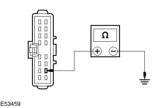
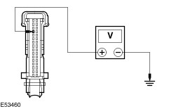
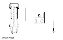
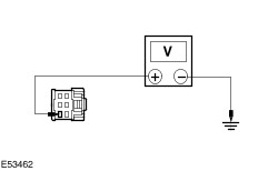
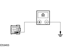
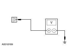
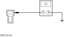
Symptom Chart Symptom Chart | Symptom | Possible Sources | Action | | The headlamp switch illumination is inoperative | * Fuse. * Circuit(s). * Headlamp switch. | * | | The Instrument cluster illumination is inoperative | * Circuit(s). * Instrument cluster. | * | | The gearshift lever illumination is inoperative | * Circuit(s). * Gearshift lever unit. | * | | The cigar lighter illumination is inoperative | * Circuit(s). * Cigar lighter socket. | * | | PINPOINT TEST A : THE HEADLAMP SWITCH ILLUMINATION IS INOPERATIVE | | TEST CONDITIONS | DETAILS/RESULTS/ACTIONS | | A1: CHECK THE HEADLAMP SWITCH ILLUMINATION GROUND CIRCUIT | | | 1 Ignition switch in position 0. | | | 2 Disconnect Headlamp switch C478. | | | 3 Measure the resistance between the headlamp switch C478 pin 10, circuit 30-LE29 (BK), harness side and ground. | | | Is the resistance less than 5 ohms? Yes INSTALL a new headlamp switch. TEST the system for normal operation. No REPAIR the circuit 30-LE29 (BK). TEST the system for normal operation. | | PINPOINT TEST B : THE INSTRUMENT CLUSTER ILLUMINATION IS INOPERATIVE | | TEST CONDITIONS | DETAILS/RESULTS/ACTIONS | | B1: CHECK CIRCUIT 64S-LK19 (BU/RD) FOR VOLTAGE | | | 1 Ignition switch in position 0. | | | 2 Disconnect Instrument cluster C449. | | | 3 Place the headlamp switch in the headlamp ON position. | | | 4 Measure the voltage between the instrument cluster C449 pin 4, circuit 64S-LK19 (BU/RD), harness side and ground. | | | Is the voltage greater than 10 volts? Yes No REPAIR the circuit. TEST the system for normal operation. | | B2: CHECK CIRCUIT 91-GG14 (BK/OG) FOR OPEN | | | 1 Place the headlamp switch in the OFF position. | | | 2 Measure the resistance between the instrument cluster C449 pin 17, circuit 91-GG14 (BK/OG), harness side and ground. | | | Is the resistance less than 5 ohms? Yes INSTALL a new instrument cluster. TEST the system for normal operation. No REPAIR the circuit. TEST the system for normal operation. | | PINPOINT TEST C : THE GEARSHIFT ILLUMINATION IS INOPERATIVE | | TEST CONDITIONS | DETAILS/RESULTS/ACTIONS | | C1: CHECK CIRCUIT 64S-LK21 (BU/BK) FOR VOLTAGE | | | 1 Disconnect Gearshift lever unit C600. | | | 2 Place the headlamp switch in the headlamp ON position. | | | 3 Measure the voltage between the gearshift lever unit C600 pin 2, circuit 64S-LK21 (BU/BK), harness side and ground. | | | Is the voltage greater than 10 volts? Yes No REPAIR the circuit. TEST the system for normal operation. | | C2: CHECK CIRCUIT 31-TA35 (BK) FOR OPEN | | | 1 Measure the resistance between the gearshift lever unit C600 pin 1, circuit 31-TA35 (BK), harness side and ground. | | | Is the resistance less than 5 ohms? Yes INSTALL a new gearshift lever unit. TEST the system for normal operation. No REPAIR the circuit. TEST the system for normal operation. | | PINPOINT TEST D : THE CIGAR LIGHTER ILLUMINATION IS INOPERATIVE | | TEST CONDITIONS | DETAILS/RESULTS/ACTIONS | | D1: CHECK CIRCUIT 64S-LK15 (BU/WH) FOR VOLTAGE | | | 1 Ignition switch in position 0. | | | 2 Disconnect Cigar lighter C410. | | | 3 Place the headlamp switch in the headlamp ON position. | | | 4 Measure the voltage between the cigar lighter C410 pin 2, circuit 64S-LK21 (BU/WH), harness side and ground. | | | Is the voltage greater than 10 volts? Yes No REPAIR the circuit. TEST the system for normal operation. | | D2: CHECK CIRCUIT 31-HA6 (BK) FOR OPEN | | | 1 Connect Cigar lighter C410. | | | 2 Disconnect Cigar lighter C411. | | | 3 Measure the resistance between the cigar lighter C912 pin 1, circuit 31-HA6 (BK), harness side and ground. | | | Is the resistance less than 5 ohms? Yes INSTALL a new cigar lighter. TEST the system for normal operation. No REPAIR the circuit. TEST the system for normal operation. | |