| Diagnosis and Testing Refer to Wiring Diagrams Section 413-13, for schematic and connector information. Principles of Operation The parking aid system detects objects behind the vehicle when the vehicle reverse gear select input to the parking aid module is enabled. The parking aid module does this by calculating the distance to an object by the use of four parking aid sensors mounted in the rear bumper. The sensors can detect objects approximately 1.5 meters to the rear of the vehicle. An intermittent warning tone is generated from the speaker in the parking aid speaker, located on the central junction box (CJB). The interval between the tones decreases as the vehicle gets closer to an object. When an object is detected within 30 cm of the sensors (40 cm on vehicles with tow bar), the warning tone becomes continuous. Refer to the Owner Guide for the parking aid speaker operation. A short tone will sound from the parking aid speaker as a system check when the ignition switch is turned to position II and reverse gear is engaged. The system will always enable when the ignition switch is turned to position II and reverse gear is engaged. The parking aid system will be disabled if reverse gear is disengaged or if a concern is detected in one of the four parking aid sensors or the parking aid module. When the parking aid system is enabled and a concern is detected, the system will indicate this by a continuous tone from the parking aid speaker. If a short circuit is detected in the parking aid resistance plug (if equipped), the system will indicate this by emitting an audible tone from the parking aid speaker for three seconds followed by a break for three seconds. This sequence will be repeated until reverse gear is disengaged. Inspection and Verification - Verify the customer concern.
- Visually inspect for obvious signs of electrical damage.
Visual Inspection Chart | Electrical | - Fuse(s)
- Relay(s)
- Wiring harness
- Electrical connector(s)
- Parking aid sensor(s)
- Parking aid speaker
- Reversing lamp switch
- Parking aid module
- Parking aid resistance plug (if equipped)
| - If an obvious cause for an observed or reported concern is found, correct the cause (if possible) before proceeding to the next step.
- If the cause is not visually evident, refer to the Parking Aid Module Reset Procedure or the Self-Diagnostic Mode.
Parking Aid Module Reset Procedure - Vehicles With Parking Aid Resistance Plug - Turn the ignition key to position 0.
- Disconnect the parking aid resistance plug.
- Turn the ignition key to position II.
- Select the reverse gear and then deselect the reverse gear.
- Turn the ignition key to position 0.
- Connect the parking aid resistance plug.
- TEST the system for normal operation. If the concern persists, refer to the Self-Diagnostic Mode - Vehicles With Parking Aid Resistance Plug.
Self-Diagnostic Mode - Vehicles With Parking Aid Resistance Plug - To enter the parking aid module Self-Diagnostic Mode, turn the ignition key to position 0, remove the parking aid resistance plug and make sure the vehicle is in the neutral gear.
- Make sure that no obstacle is within 2 meters of the rear of the vehicle.
- Turn the ignition key to position II and select the reverse gear.
- If a concern is detected with a parking aid sensor, the parking aid module will indicate this by emitting a deep audible tone sequence from the parking aid speaker. REFER to the Audible Tone Sequence Chart.
- To exit the Self-Diagnostic Mode, select the neutral gear, turn the ignition key to position 0 and install the parking aid resistance plug.
Self-Diagnostic Mode - Vehicles Without Parking Aid Resistance Plug - To enter the parking aid module Self-Diagnostic mode, make sure that no obstacle is within 2 meters of the rear of the vehicle, turn the ignition key to position II and select the reverse gear.
- Self-Diagnostic Mode begins automatically each time the parking aid system is activated and will be indicated by an audible tone for three seconds from the parking aid speaker, and is paused for one second.
- If a concern is detected with a parking aid sensor, the parking aid module will indicate this by emitting an audible tone sequence from the parking aid speaker.
- If there is a concern with more than one parking aid sensor, a second sequence will be emitted after the first.
- To exit the Self-Diagnostic Mode, select the neutral gear and turn the ignition key to position 0.
Audible Tone Sequence Chart | Audible Tone Sequence | Description | Action | | ON for three seconds, pause for one second | Opening sequence for concern diagnostics | - | | ON and OFF once, pause for one second | Right-hand outer sensor concern | REFER to the Component Test in this procedure. | | ON and OFF twice, pause for one second | Right-hand inner sensor concern | REFER to the Component Test in this procedure. | | ON and OFF three times, pause for one second | Left-hand inner sensor concern | REFER to the Component Test in this procedure. | | ON and OFF four times, pause for one second | Left-hand outer sensor concern | REFER to the Component Test in this procedure. | | ON for seventy five milliseconds, pause for seventy five milliseconds | Module concern. Low battery voltage. Short in parking aid resistance plug circuit. | GO to Pinpoint Test A. | - If the concern remains after the Self-Diagnostic Mode, refer to the Symptom Chart.
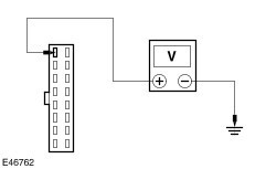
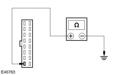
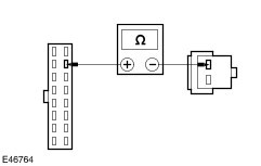
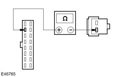
Symptom Chart | Symptom | Possible Sources | Action | | A continuous audible tone is emitted | * Parking aid sensor(s). * Parking aid module. | * REFER to the Self-Diagnostic Mode. | | The parking aid speaker has a continuous or intermittent tone when the reverse gear is selected | * Parking aid sensor(s) dirty or iced over. * Parking aid sensor(s) incorrectly installed. | * CLEAN the rear parking aid sensor(s). * INSTALL the rear parking aid sensor(s) correctly. | | Parking aid is inoperative/does not operate correctly | * Parking aid module. * Reversing lamp switch. * Circuit(s). * Parking aid speaker. | * | Pinpoint Test | PINPOINT TEST A : PARKING AID IS INOPERATIVE/DOES NOT OPERATE CORRECTLY | | TEST CONDITIONS | DETAILS/RESULTS/ACTIONS | | A1: CHECK THE REVERSING LAMP SWITCH | | | 1 Ignition switch in position II. | | | 2 Select reverse gear. | | | Are the reversing lamps operating correctly? Yes No REFER to: Reversing Lamps (417-01 Exterior Lighting, Diagnosis and Testing). | | A2: CHECK THE PARKING AID MODULE POWER SUPPLY | | | 1 Ignition switch in position 0. | | | 2 Disconnect Parking Aid Module C2100a. | | | 3 Ignition switch in position II. | | | 4 Select reverse gear. | | | 5 Measure the voltage between the parking aid module C2100a pin 1, circuit 15S-GN11 (GN/BU), harness side and ground. | | | Is the voltage greater than 10 volts? Yes No CHECK and REPAIR the circuit between the parking aid module C2100a pin 1, circuit 15S-GN11 (GN/BU), harness side and reversing lamp switch C181 pin 2, circuit 15S-LG9 (GN/BK) (manual transaxle), or transmission range (TR) sensor C187 pin 3, circuit 15S-LG9 (GN/BK) (automatic transaxle), harness side. If the circuit is OK, INSTALL a new parking aid module. TEST the system for normal operation. | | A3: CHECK THE PARKING AID MODULE GROUND CIRCUIT | | | 1 Ignition switch in position 0. | | | 2 Measure the resistance between the parking aid module C2100a pin 8, circuit 31-GN10B (BK), harness side and ground. | | | Is the resistance less than 5 ohms? Yes No CHECK and REPAIR the circuit between the parking aid module C2100a pin 8, circuit 31-GN10B (BK), harness side and ground. If the circuit is OK, INSTALL a new parking aid module. TEST the system for normal operation. | | A4: CHECK THE PARKING AID SPEAKER CIRCUIT FOR OPEN | | | 1 Ignition switch in position 0. | | | 2 Disconnect Parking Aid Speaker C2109. | | | 3 Measure the resistance between the parking aid module C2100a pin 10, circuit 8-XL6 (WH/BU), harness side and the parking aid speaker C2109 pin 1, circuit 8-XL6 (WH/BU), harness side. | | | Is the resistance less than 5 ohms? Yes No REPAIR the circuit between the parking aid module C2100a pin 10, circuit 8-XL6 (WH/BU), harness side and the parking aid speaker C2109 pin 1, circuit 8-XL6 (WH/BU), harness side. If the circuit is OK, INSTALL a new parking aid speaker. TEST the system for normal operation. | | A5: CHECK THE PARKING AID SPEAKER CIRCUIT FOR OPEN | | | 1 Measure the resistance between the parking aid module C2100a pin 2, circuit 8-XL7 (WH/GN), harness side and the parking aid speaker C2109 pin 2, circuit 8-XL7 (WH/GN), harness side. | | | Is the resistance less than 5 ohms? Yes INSTALL a new parking aid module. TEST the system for normal operation. No REPAIR the circuit between the parking aid module C2100a pin 2, circuit 8-XL7 (WH/GN), harness side and the parking aid speaker C2109 pin 2, circuit 8-XL7 (WH/GN), harness side. If the circuit is OK, INSTALL a new parking aid speaker. TEST the system for normal operation. | Component Tests Parking Aid Sensor Wiring Harness NOTE:Refer to Wiring Diagrams Section 413-13, for schematic and connector information. NOTE:Check the parking aid wiring harness for short to ground, short to battery or damage. - Test the parking aid sensor wiring harness using the following table as a guide to meter lead placement as well as expected values.
| Parking Aid Sensor Outer Right C2108 | Parking Aid Module C2100b | Expected Value | Action | | Pin 1 | Pin 6 | Less than 1 ohm | If the resistance is greater than 1 ohm, CHECK and REPAIR the circuit. If the circuit is OK, INSTALL a new parking aid sensor. TEST the system for normal operation | | Pin 2 | Pin 4 | Less than 1 ohm | If the resistance is greater than 1 ohm, CHECK and REPAIR the circuit. If the circuit is OK, INSTALL a new parking aid sensor. TEST the system for normal operation | | Pin 3 | Pin 1 | Less than 1 ohm | If the resistance is greater than 1 ohm, CHECK and REPAIR the circuit. If the circuit is OK, INSTALL a new parking aid sensor. TEST the system for normal operation | | Parking Aid Sensor Inner Right C2107 | Parking Aid Module C2100b | Expected Value | Action | | Pin 1 | Pin 6 | Less than 1 ohm | If the resistance is greater than 1 ohm, CHECK and REPAIR the circuit. If the circuit is OK, INSTALL a new parking aid sensor. TEST the system for normal operation | | Pin 2 | Pin 2 | Less than 1 ohm | If the resistance is greater than 1 ohm, CHECK and REPAIR the circuit. If the circuit is OK, INSTALL a new parking aid sensor. TEST the system for normal operation | | Pin 3 | Pin 1 | Less than 1 ohm | If the resistance is greater than 1 ohm, CHECK and REPAIR the circuit. If the circuit is OK, INSTALL a new parking aid sensor. TEST the system for normal operation | | Parking Aid Sensor Inner Left C2106 | Parking Aid Module C2100b | Expected Value | Action | | Pin 1 | Pin 6 | Less than 1 ohm | If the resistance is greater than 1 ohm, CHECK and REPAIR the circuit. If the circuit is OK, INSTALL a new parking aid sensor. TEST the system for normal operation | | Pin 2 | Pin 3 | Less than 1 ohm | If the resistance is greater than 1 ohm, CHECK and REPAIR the circuit. If the circuit is OK, INSTALL a new parking aid sensor. TEST the system for normal operation | | Pin 3 | Pin 1 | Less than 1 ohm | If the resistance is greater than 1 ohm, CHECK and REPAIR the circuit. If the circuit is OK, INSTALL a new parking aid sensor. TEST the system for normal operation | | Parking Aid Sensor Outer Left C2105 | Parking Aid Module C2100b | Expected Value | Action | | Pin 1 | Pin 6 | Less than 1 ohm | If the resistance is greater than 1 ohm, CHECK and REPAIR the circuit. If the circuit is OK, INSTALL a new parking aid sensor. TEST the system for normal operation | | Pin 2 | Pin 5 | Less than 1 ohm | If the resistance is greater than 1 ohm, CHECK and REPAIR the circuit. If the circuit is OK, INSTALL a new parking aid sensor. TEST the system for normal operation | | Pin 3 | Pin 1 | Less than 1 ohm | If the resistance is greater than 1 ohm, CHECK and REPAIR the circuit. If the circuit is OK, INSTALL a new parking aid sensor. TEST the system for normal operation | |