| Diagnosis and Testing Refer to Wiring Diagrams Section 415-01, for schematic and connector information.Refer to Wiring Diagrams Section 415-03, for schematic and connector information.Refer to Wiring Diagrams Section 415-07, for schematic and connector information. Worldwide Diagnostic System (WDS) Inspection and Verification NOTE:If the code is entered incorrectly 3 times, the system will lock out. The component can only be unlocked by the manufacturer. - Verify the customer concern.
- Visually inspect for obvious signs of mechanical or electrical damage.
Visual Inspection Chart | Mechanical | Electrical | - Audio unit
- Antenna
- Foreign objects contacting speaker
- Trim poorly fitted/resonance
- Audio control switch (if equipped)
- Rear auxiliary audio control (if equipped)
- Compact disc (CD) changer
- Digital versatile disc (DVD) player
| - Fuse(s)
- Wiring harness
- Electrical connector(s)
- Audio unit
- Audio control switch (if equipped)
- Rear auxiliary audio control (if equipped)
- CD changer
- Central junction box (CJB)
- Remote control battery(s)
- Remote control
- Video display
- DVD player
- Video system module
- Passenger entertainment control panel
- External game/media source (games console/video camera etc)
| - If an obvious cause for an observed or reported concern is found, correct the cause (if possible) before proceeding to the next step.
- If the cause is not visually evident, verify the symptom and refer to the Self-Diagnostic Mode.
Self-Diagnostic Mode - Low Series Audio Unit NOTE:The audio unit must be in radio mode before entering the Self-Diagnostic Mode. - To enter the audio unit Self-Diagnostic Mode, switch the audio unit ON. Within four seconds depress the preset buttons 3 and 6 together.
- Release the preset buttons 3 and 6 and the audio unit will enter the Self-Diagnostic Mode.
- To exit the Self-Diagnostic Mode, switch the audio unit OFF.
Self-Diagnostic Mode | Message Displayed | Circuit Tested | | 1. 4CH LF for four channel system 2CH LF for two channel system. | Left hand front speaker circuit. | | 2. 4CH RF for four channel system 2CH RF for two channel system. | Right hand front speaker circuit. | | 3. 4CH LR for four channel system. | Left hand rear speaker circuit. | | 4. 4CH RR for four channel system. | Right hand rear speaker circuit. | - If the cause is not evident after the Self-Diagnostic Mode, connect WDS to the data link connector (DLC).
- Retrieve the Diagnostic Trouble Code (DTC)s and refer to the DTC Index Chart.
Self-Diagnostic Mode - High Series Audio Unit NOTE:The audio unit must be in radio mode before entering the Self-Diagnostic Mode. - To enter the audio unit Self-Diagnostic Mode, switch the audio unit ON. Within four seconds depress the preset button 4 and TA together.
- Release the preset button 4 and TA and the audio unit will enter the Self-Diagnostic Mode.
- To exit the Self-Diagnostic Mode, switch the audio unit OFF.
Self-Diagnostic Mode | Message Displayed | Circuit Tested | | 1. 4CH LF for four channel system 2CH LF for two channel system. | Left hand front speaker circuit. | | 2. 4CH RF for four channel system 2CH RF for two channel system. | Right hand front speaker circuit. | | 3. 4CH LR for four channel system. | Left hand rear speaker circuit. | | 4. 4CH RR for four channel system. | Right hand rear speaker circuit. | | 5. FM frequency received. | Antenna cable. | - If the cause is not evident after the Self-Diagnostic Mode, connect WDS to the data link connector (DLC).
- Retrieve the Diagnostic Trouble Code (DTC)s and refer to the DTC Index Chart.
Diagnostic Trouble Code (DTC) Index Chart Diagnostic Trouble Code (DTC) Index Chart - Audio Unit | DTC | Description/Condition | Possible Source | Action | | B1342 | Audio unit internal failure | Audio unit | INSTALL a new audio unit.
REFER to: Audio Unit - Vehicles Built From: 06/2003 (415-01 Audio Unit, Removal and Installation).
| | B2401 | Tape player failure | Audio unit | INSTALL a new audio unit.
REFER to: Audio Unit - Vehicles Built From: 06/2003 (415-01 Audio Unit, Removal and Installation).
| | B2403 | CD player internal failure | Audio unit | INSTALL a new audio unit.
REFER to: Audio Unit - Vehicles Built From: 06/2003 (415-01 Audio Unit, Removal and Installation).
| | B2404 | Audio control switch circuit failure | Audio control switch | GO to Pinpoint Test E. | | B2406 | CD player internal failure | Audio unit | INSTALL a new audio unit.
REFER to: Audio Unit - Vehicles Built From: 06/2003 (415-01 Audio Unit, Removal and Installation).
| | B2408 | Speaker line short circuit | Speaker(s) | GO to Pinpoint Test D. | | B2409 | AM receiving signal error | Antenna cable | GO to Pinpoint Test B. | | B2410 | FM receiving signal error | Antenna cable | GO to Pinpoint Test B. | | B2477 | Module configuration failure | Audio unit and central junction box (CJB) | REFER to WDS. | | P1628 | Module ignition supply input | CJB | REFER to WDS. | Diagnostic Trouble Code (DTC) Index Chart - CD Changer | DTC | Description/Condition | Possible Source | Action | | B1342 | CD changer defective | CD changer | INSTALL a new CD changer.
REFER to: Compact Disc (CD) Changer - Vehicles Built From: 06/2003 (415-01 Audio Unit, Removal and Installation).
| | B2403 | CD changer internal failure | CD changer | INSTALL a new CD changer.
REFER to: Compact Disc (CD) Changer - Vehicles Built From: 06/2003 (415-01 Audio Unit, Removal and Installation).
| - If the cause is still evident, refer to the Symptom Chart.
Symptom Chart | Symptom | Possible Sources | Action | | The audio unit is inoperative/does not operate correctly | * Circuit(s). * Audio unit. * Auxiliary socket. | * | | The display is blank - radio and cassette player operate | * Audio unit. | * INSTALL a new audio unit.
REFER to: Audio Unit - Vehicles Built From: 06/2003 (415-01 Audio Unit, Removal and Installation).
| | The display is blank - radio and CD player operate | * Audio unit. | * INSTALL a new audio unit.
REFER to: Audio Unit - Vehicles Built From: 06/2003 (415-01 Audio Unit, Removal and Installation).
| | Poor reception | * Antenna. * Antenna cable. * Audio unit. | * | | Poor quality/distorted sound from one or more speakers (not all speakers) | * Speaker(s). * Circuit(s). * Audio unit. | * | | No sound from all speakers | * Audio unit. | * INSTALL a new audio unit.
REFER to: Audio Unit - Vehicles Built From: 06/2003 (415-01 Audio Unit, Removal and Installation).
TEST the system for normal operation. | | No sound from one or more of the speakers (not all speakers) | * Speaker(s). * Circuit(s). * Audio unit. | * | | The auxiliary audio control is inoperative/does not operate correctly. | * Circuit(s). * Auxiliary audio control switch. * Rear auxiliary audio control. * Audio unit. | * | | The CD changer is inoperative/does not operate correctly | * Circuit(s). * CD changer. * Audio unit. | * | | The audio unit illumination is inoperative | * Circuit(s). * Audio unit. * Genetic electronic module (GEM). | * REFER to: Instrument Cluster and Panel Illumination (413-00 Instrument Cluster and Panel Illumination, Diagnosis and Testing). | | The video system is inoperative/does not operate correctly | * Remote control. * Remote control batteries. | * CHECK the remote control batteries for correct voltage. If the remote control batteries are not to correct specification. Install new batteries to the remote control. TEST the system for normal operation. | | * Contaminated DVD disc(s). | * CLEAN the DVD disc(s) using lint free material. TEST the system for normal operation. | | * Circuit(s). * Video system module. * Video display. * Audio unit. | * | | * DVD player. | * | | No auxiliary headphone audio | * Contaminated DVD disc(s). | * CLEAN the DVD disc(s) using lint free material. TEST the system for normal operation. | | * Headphone(s). * Circuit(s). * Passenger entertainment control panel. * Video system module. | * | | * DVD player. | * | | * External game/media source (games console/video camera etc). | * Not Ford responsibility. REFER the customer to the game/media source supplier. | | The video display is inoperative/does not operate correctly | * Contaminated DVD disc(s). | * CLEAN the DVD disc(s) using lint free material. TEST the system for normal operation. | | * Circuit(s). * Video display. * Video system module. | * | | * DVD player. | * | | * External game/media source (games console/video camera etc). | * Not Ford responsibility. REFER the customer to the game/media source supplier. | | The DVD player is inoperative/does not operate correctly | * Contaminated DVD disc(s). | * CLEAN the DVD disc(s) using lint free material. TEST the system for normal operation. | | * Circuit(s). * DVD player. * Audio unit. | * | | The remote control is inoperative/does not operate correctly | * Remote control. * Circuit(s). * Video display infrared sensor. * Video system module. | * | | External game console/media source is inoperative/does not operate correctly | * External game/media source (games console/video camera etc). | * Not Ford responsibility. REFER the customer to the game/media source supplier. | | * Inverter cable. | * Not Ford responsibility. REFER the customer to the inverter cable supplier. | | * Circuit(s). * Passenger entertainment control panel. * Video system module. | * | | No DVD player on-screen menu options display | * DVD player. | * INSTALL a new DVD player.
REFER to: Digital Versatile Disc (DVD) Player (415-07 Video System, Removal and Installation).
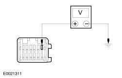
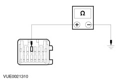
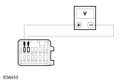
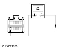
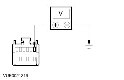
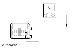
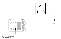
| Pinpoint Tests CAUTION:If the audio unit is to be removed for testing or new component installation, remove any audio media (if possible) from within the audio unit and return it to the customer. Failure to follow this instruction may result in damage to the audio unit. NOTE:Use a digital multimeter for all electrical measurements. | PINPOINT TEST A : THE AUDIO UNIT IS INOPERATIVE/DOES NOT OPERATE CORRECTLY | | TEST CONDITIONS | DETAILS/RESULTS/ACTIONS | | A1: CHECK FOR VOLTAGE TO AUDIO UNIT | | | 1 Disconnect Audio Unit C518. | | | 2 Ignition switch in position I. | | | 3 Measure the voltage between the audio unit C518 pin 15, circuit 29-MD15 (OG/BK), harness side and ground, and between the audio unit C518 pin 16, circuit 75-MD15 (YE/GN), harness side and ground. | | | Are the voltages greater than 10 volts? Yes No REPAIR circuit 29-MD15 (OG/BK) or circuit 75-MD15 (YE/GN). TEST the system for normal operation. | | A2: CHECK THE AUDIO UNIT GROUND CIRCUITS FOR OPEN | | | 1 Ignition switch in position 0. | | | 2 Measure the resistance between the audio unit C518 pin 11, circuit 91-MD34 (BK/YE), harness side and ground, and between the audio unit C518 pin 12, circuit 91-MD15A (BK/GN), harness side and ground. | | | Are the resistances less than 1 ohm? Yes No REPAIR circuit 91-MD34 (BK/YE) or 91-MD15A (BK/GN). TEST the system for normal operation. | | A3: CHECK CIRCUIT 31-MD15 (BK) TO GROUND | | | 1 Connect Audio Unit C518. | | | 2 Disconnect Audio Unit C519. | | | 3 Measure the resistance between the audio unit C519 pin 6, circuit 31-MD15 (BK), harness side and ground. | | | Is the resistance less than 1 ohm? Yes No REPAIR circuit 31-MD15 (BK) . TEST the system for normal operation. | | A4: CHECK THE AUXILIARY SOCKET TO AUDIO UNIT FOR CONTINUITY | | | 1 Disconnect Auxiliary Socket C1022. | | | 2 Measure the resistances between the audio unit C519, harness side and the auxiliary socket C1022, harness side: - audio unit C519 pin 5, circuit 1-MD35 (WH/BU), harness side and the auxiliary socket C1022 pin 4, circuit 1-MD35 (WH/BU), harness side.
- audio unit C519 pin 6, circuit 3-MD15 (BN/GN), harness side and the auxiliary socket C1022 pin 3, circuit 3-MD15 (BN/GN), harness side.
- audio unit C519 pin 11, circuit 1-MD36 (WH/GN), harness side and the auxiliary socket C1022 pin 1, circuit 1-MD36 (WH/GN), harness side.
| | | Are the resistances less than 1 ohm? Yes INSTALL a new audio unit.
REFER to: Audio Unit - Vehicles Built From: 06/2003 (415-01 Audio Unit, Removal and Installation).
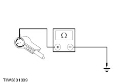
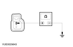
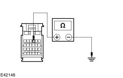
TEST the system for normal operation. No REPAIR the circuit(s) as necessary. TEST the system for normal operation. If the concern persists, INSTALL a new | | PINPOINT TEST B : POOR RECEPTION | | TEST CONDITIONS | DETAILS/RESULTS/ACTIONS | | B1: CHECK THE ANTENNA CABLE SHIELD | | | 1 Ignition switch in position 0. | | | 2 Disconnect the antenna cable from the audio unit. | | | 3 Measure the resistance between the antenna cable ground connector (shield), and ground. | | | Is the resistance less than 1 ohm? Yes No CLEAN and TIGHTEN the antenna base connection to the body. If the concern persists, INSTALL a new antenna cable.
REFER to: Antenna Cable (415-02 Antenna, Removal and Installation).
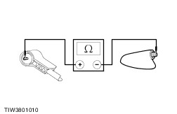
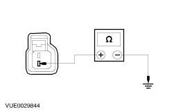
TEST the system for normal operation. | | B2: CHECK THE ANTENNA CENTER CONDUCTOR FOR OPEN | | | 1 Remove the antenna mast. | | | 2 Measure the resistance of the center conductor between the ends of the antenna cable. | | | Is the resistance less than 1 ohm? Yes No INSTALL a new antenna cable.
REFER to: Antenna Cable (415-02 Antenna, Removal and Installation).
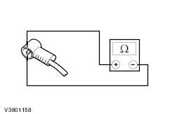
TEST the system for normal operation. | | B3: CHECK ANTENNA CABLE FOR SHORT | | | 1 Measure the resistance between the antenna center conductor and the antenna ground (shield). | | | Is the resistance greater than 10,000 ohms (open circuit)? Yes CLEAN and TIGHTEN the ground connections at the base of the antenna and battery negative cable to the body. If concern the persists, INSTALL a new audio unit.
REFER to: Audio Unit - Vehicles Built From: 06/2003 (415-01 Audio Unit, Removal and Installation).
TEST the system for normal operation. No INSTALL a new antenna cable.
REFER to: Antenna Cable (415-02 Antenna, Removal and Installation).
TEST the system for normal operation. If the concern persists, INSTALL a new audio unit.
REFER to: Audio Unit - Vehicles Built From: 06/2003 (415-01 Audio Unit, Removal and Installation).
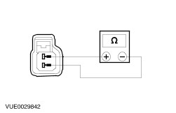
| | PINPOINT TEST C : POOR QUALITY/DISTORTED SOUND FROM ONE OR MORE SPEAKERS (NOT ALL SPEAKERS) | | TEST CONDITIONS | DETAILS/RESULTS/ACTIONS | | C1: CHECK THE SPEAKER RESISTANCE | | | 1 Disconnect Affected Speaker. | | | 2 Measure the resistance between the affected speaker pin 1 and pin 2, component side. | | | Is the resistance 4.0 ohms? Yes No INSTALL a new speaker. TEST the system for normal operation. | | C2: CHECK SPEAKER INPUT FOR SHORT TO GROUND | | | 1 Disconnect Audio Unit C517. | | | 2 Measure the resistance between the affected speaker connector pin 1, harness side and ground. | | | Is the resistance greater than 10,000 ohms (open circuit)? Yes No REPAIR speaker input circuit. TEST the system for normal operation. | | C3: CHECK SPEAKER RETURN FOR SHORT TO GROUND | | | 1 Measure the resistance between the affected speaker connector pin 2, harness side and ground. | | | Is the resistance greater than 10,000 ohms (open circuit)? Yes INSTALL a new speaker. TEST the system for normal operation. If the concern persists, INSTALL a new audio unit.
REFER to: Audio Unit - Vehicles Built From: 06/2003 (415-01 Audio Unit, Removal and Installation).
No REPAIR speaker return circuit. TEST the system for normal operation. | | PINPOINT TEST D : NO SOUND FROM ONE OR MORE OF THE SPEAKERS (NOT ALL SPEAKERS) | | TEST CONDITIONS | DETAILS/RESULTS/ACTIONS | | D1: CHECK THE SPEAKER RESISTANCE | | | 1 Disconnect Inoperative Speaker. | | | 2 Measure the resistance between the inoperative speaker pin 1 and pin 2, component side. | | | Is the resistance 4.0 ohms? Yes No INSTALL a new speaker(s). TEST the system for normal operation. | | D2: CHECK THE INOPERATIVE SPEAKER(S) CONNECTOR PIN 2 CIRCUIT | | | 1 Disconnect Audio Unit C517. | | | 2 Measure the resistance between the following audio unit C517 pins, harness side and the inoperative speaker(s) connector pin 2, harness side: - (Left front speaker) C720 pin 2, circuit 8-MD28 (WH) to C517 pin 3, circuit 8-MD10 (WH/BK).
- (Right front speaker) C723 pin 2, circuit 8-MD28 (WH) to C517 pin 2, circuit 8-MD17 (WH/RD).
- (Left rear speaker) C722 pin 2, circuit 8-MD29 (WH/VT) to C517 pin 4, circuit 8-MD11 (WH/VT).
- (Right rear speaker) C724 pin 2, circuit 8-MD29 (WH/VT) to C517 pin 1, circuit 8-MD18 (WH).
| | | Is the resistance less than 1 ohm? Yes No REPAIR the circuit in question. TEST the system for normal operation. | | D3: CHECK THE INOPERATIVE SPEAKER(S) CONNECTOR PIN 1 CIRCUIT | | | 1 Measure the resistance between the following audio unit C517 pins, harness side and the inoperative speaker(s) connector pin 1, harness side: - (Left front speaker) C720 pin 1, circuit 10-MD28 (GY) to C517 pin 7, circuit 10-MD10 (GY/BK).
- (Right front speaker) C723 pin 1, circuit 10-MD28 (GY) to C517 pin 6, circuit 10-MD17 (GY/RD).
- (Left rear speaker) C722 pin 1, circuit 10-MD29 (GY/WH) to C517 pin 8, circuit 10-MD11 (GY/WH).
- (Right rear speaker) C724 pin 1, circuit 10-MD29 (GY/WH) to C517 pin 5, 10-MD18 (GY).
| | | Is the resistance less than 1 ohm? Yes No REPAIR the circuit in question. TEST the system for normal operation. | | D4: CHECK THE INOPERATIVE SPEAKER(S) CIRCUIT FOR SHORT TO GROUND | | | 1 Measure the resistance between the following inoperative speaker(s) connector pin 1, harness side and ground: - (Left front speaker) C720 pin 1, circuit 10-MD28 (GY), to ground.
- (Right front speaker) C723 pin 1, circuit 10-MD28 (GY), to ground.
- (Left rear speaker) C722 pin 1, circuit 10-MD29 (GY/WH), to ground.
- (Right rear speaker) C724 pin 1, 10-MD29B (GY/WH), to ground.
| | | Is the resistance greater than 10,000 ohms (open circuit)? Yes INSTALL a new speaker. TEST the system for normal operation. If the concern persists, INSTALL a new audio unit.
REFER to: Audio Unit - Vehicles Built From: 06/2003 (415-01 Audio Unit, Removal and Installation).
No REPAIR the circuit in question. TEST the system for normal operation. | | PINPOINT TEST E : THE AUXILIARY AUDIO CONTROL SWITCH IS INOPERATIVE/DOES NOT OPERATE CORRECTLY | | TEST CONDITIONS | DETAILS/RESULTS/ACTIONS | | E1: CHECK THE AUDIO UNIT OPERATES CORRECTLY WITHOUT USING THE AUXILIARY AUDIO CONTROL SWITCH(ES) | | | 1 Operate the audio unit without the auxiliary audio control switch(es). | | | Does the audio unit operate correctly without using the auxiliary audio control switch(es)? Yes Operate the audio unit with the auxiliary audio control switch. If the auxiliary audio control switch is inoperative, GO to E2. Operate the audio unit with the rear auxiliary audio control. If the rear auxiliary audio control is inoperative, GO to E4. No INSTALL a new audio unit.
REFER to: Audio Unit - Vehicles Built From: 06/2003 (415-01 Audio Unit, Removal and Installation).
TEST the system for normal operation. | | E2: CHECK THE CIRCUIT 8-MD26 (WH/BK) FOR OPEN | | | 1 Disconnect Audio Unit C520. | | | 2 Disconnect Auxiliary Audio Control Switch C487. | | | 3 Measure the resistance between the audio unit C520 pin 6, circuit 8-MD26 (WH/BK) harness side and the auxiliary audio control switch C487 pin 1, circuit 8-MD26 (WH/BK) harness side. | | | Is the resistance less than 1 ohm? Yes No REPAIR the circuit. TEST the system for normal operation. | | E3: CHECK CIRCUIT 9-MD26 (BN/YE) FOR OPEN | | | 1 Measure the resistance between the audio unit C520 pin 8, circuit 9-MD26 (BN/YE) harness side and the auxiliary audio control switch C487 pin 2, circuit 9-MD26 (BN/YE) harness side. | | | Is the resistance less than 1 ohm? Yes INSTALL a new auxiliary audio control switch. TEST the system for normal operation. If the concern persists, INSTALL a new audio unit.
REFER to: Audio Unit - Vehicles Built From: 06/2003 (415-01 Audio Unit, Removal and Installation).
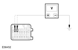
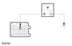
No REPAIR the circuit. TEST the system for normal operation. | | E4: CHECK CIRCUIT 29-MD16 (OG/GN) FOR VOLTAGE | | | 1 Disconnect Rear Auxiliary Audio Control C605. | | | 2 Measure the voltage between the rear auxiliary audio control C605 pin 8, circuit 29-MD16 (OG/GN), harness side and ground. | | | Is the voltage greater than 10 volts? Yes No REPAIR the circuit. TEST the system for normal operation. | | E5: CHECK CIRCUIT 91-MD16 (BK/RD) FOR GROUND | | | 1 Measure the resistance between the rear auxiliary audio control C605 pin 3, circuit 91-MD16 (BK/RD), harness side and ground. | | | Is the resistance less than 1 ohm? Yes No REPAIR the circuit. TEST the system for normal operation. | | E6: CHECK CIRCUIT 2-MD18 (GY) FOR OPEN | | | 1 Disconnect Audio Unit C520. | | | 2 Measure the resistance between the rear auxiliary audio control C605 pin 9, circuit 2-MD18 (GY), harness side and the audio unit C520 pin 8, circuit 2-MD18 (GY), harness side. | | | Is the resistance less than 1 ohm? Yes No REPAIR the circuit. TEST the system for normal operation. | | E7: CHECK CIRCUIT 1-MD18 (WH) FOR OPEN | | | 1 Measure the resistance between the rear auxiliary audio control C605 pin 10, circuit 1-MD18 (WH), harness side and the audio unit C520 pin 2, circuit 1-MD18 (WH), harness side. | | | Is the resistance less than 1 ohm? Yes No REPAIR the circuit. TEST the system for normal operation. | | E8: CHECK CIRCUIT 2-MD11 (GY/WH) FOR OPEN | | | 1 Measure the resistance between the rear auxiliary audio control C605 pin 4, circuit 2-MD11 (GY/WH), harness side and the audio unit C520 pin 7, circuit 2-MD11 (GY/WH), harness side. | | | Is the resistance less than 1 ohm? Yes No REPAIR the circuit. TEST the system for normal operation. | | E9: CHECK CIRCUIT 1-MD11 (WH/VT) FOR OPEN | | | 1 Measure the resistance between the rear auxiliary audio control C605 pin 5, circuit 1-MD11 (WH/VT), harness side and the audio unit C520 pin 1, circuit 1-MD11 (WH/VT), harness side. | | | Is the resistance less than 1 ohm? Yes INSTALL a new rear auxiliary audio control.
REFER to: Rear Auxiliary Audio Controls (415-01 Audio Unit, Removal and Installation).
TEST the system for normal operation. No REPAIR the circuit. TEST the system for normal operation. If the concern persists, INSTALL a new audio unit.
REFER to: Audio Unit - Vehicles Built From: 06/2003 (415-01 Audio Unit, Removal and Installation).
TEST the system for normal operation. | | PINPOINT TEST F : THE CD CHANGER IS INOPERATIVE/DOES NOT OPERATE CORRECTLY | | TEST CONDITIONS | DETAILS/RESULTS/ACTIONS | | F1: CHECK THE CD CHANGER FOR VOLTAGE | | | 1 Disconnect CD Changer C465. | | | 2 Measure the voltage between the CD changer C465 pin 9, circuit 29-MD8 (OG), harness side and ground. | | | Is the voltage greater than 10 volts? Yes No REPAIR circuit 29-MD8 (OG). TEST the system for normal operation. | | F2: CHECK THE CD CHANGER FOR GROUND | | | 1 Measure the resistance between the CD changer C465 pin 3, circuit 91-MD8 (BK/OG), harness side and ground. | | | Is the resistance less than 1 ohm? Yes No REPAIR the circuit 91-MD8 (BK/OG). TEST the system for normal operation. | | F3: CHECK THE CD CHANGER TO AUDIO UNIT CIRCUIT(S) FOR OPEN | | | 1 Disconnect Audio Unit C520. | | | 2 Measure the resistance between the following CD changer circuit(s) and the audio unit circuit(s): - CD changer C465 pin 5, circuit 1-MD49 (WH/GN), harness side and audio unit C520 pin 3, circuit 1-MD49 (WH/GN), harness side.
- CD changer C465 pin 11, circuit 2-MD49 (GY/OG), harness side and audio unit C520 pin 9, circuit 2-MD49 (GY/OG), harness side.
- CD changer C465 pin 6, circuit 1-MD50 (WH/BK), harness side and audio unit C520 pin 4, circuit 1-MD50 (WH/BK), harness side.
- CD changer C465 pin 12, circuit 2-MD50 (GY/BK), harness side and audio unit C520 pin 10, circuit 2-MD50 (GY/BK), harness side.
| | | Is the resistance less than 1 ohm? Yes INSTALL a new CD changer.
REFER to: Compact Disc (CD) Changer - Vehicles Built From: 06/2003 (415-01 Audio Unit, Removal and Installation).
TEST the system for normal operation. No REPAIR the circuit(s) as necessary. TEST the system for normal operation. If the concern persists, INSTALL a new audio unit.
REFER to: Audio Unit - Vehicles Built From: 06/2003 (415-01 Audio Unit, Removal and Installation).
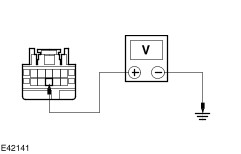
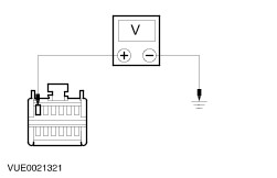
TEST the system for normal operation. | | PINPOINT TEST G : THE VIDEO SYSTEM IS INOPERATIVE/DOES NOT OPERATE CORRECTLY | WARNING:Do not attempt to open or repair a video display as there are internal voltages in excess of 2000 volts. Failure to follow this instruction may result in personal injury. | | TEST CONDITIONS | DETAILS/RESULTS/ACTIONS | | G1: CHECK FRONT SEAT BACKREST UPPER VIDEO SYSTEM(S) OPERATION USING THE REMOTE CONTROL | | | 1 Operate the front seat backrest upper video system(s) with the remote control. | | | Do the front seat backrest upper video system(s) operated by the remote control turn white? Yes For concern with left-hand front seat backrest upper video system. GO to G2. For concern with right-hand front seat backrest upper video system. GO to G4. No If the front seat backrest upper video system(s) flickers. GO to G6. If the front seat backrest upper video system(s) are blank. GO to G12. | | G2: CHECK LEFT-HAND FRONT SEAT BACKREST UPPER VIDEO SYSTEM C1036 (OG) FOR VOLTAGE | | | 1 Disconnect Left-Hand Front Seat Backrest Upper Video System C1036. | | | 2 Measure the voltage between the left-hand front seat backrest upper video system C1036 pin 6, (OG), harness side and ground. | | | Is the voltage greater than 10 volts? Yes No CHECK and REPAIR the circuit. TEST the system for normal operation. If the circuit is OK. INSTALL a new video system module.
REFER to: Video System Module - Vehicles Built From: 06/2003 (415-07 Video System, Removal and Installation).
TEST the system for normal operation. If the concern persists, Install a new wiring harness between the video system module and the left-hand front seat backrest upper video system. TEST the system for normal operation. | | G3: CHECK LEFT-HAND FRONT SEAT BACKREST UPPER VIDEO SYSTEM C1036 (BN/YE) FOR GROUND | | | 1 Measure the resistance between the left-hand front seat backrest upper video system C1036 pin 3, (BN/YE), harness side and ground. | | | Is the resistance less than 0.5 ohms? Yes INSTALL a new head restraint/video display. TEST the system for normal operation. No REPAIR the circuit. TEST the system for normal operation. | | G4: CHECK RIGHT-HAND FRONT SEAT BACKREST UPPER VIDEO SYSTEM C554 (OG) FOR VOLTAGE | | | 1 Disconnect Right-Hand Front Seat Backrest Upper Video System C554. | | | 2 Measure the voltage between the right-hand front seat backrest upper video system C554 pin 6, (OG), harness side and ground. | | | Is the voltage greater than 10 volts? Yes No CHECK and REPAIR the circuit. TEST the system for normal operation. If the circuit is OK. INSTALL a new video system module.
REFER to: Video System Module - Vehicles Built From: 06/2003 (415-07 Video System, Removal and Installation).
TEST the system for normal operation. If the concern persists, Install a new wiring harness between the video system module and the right-hand front seat backrest upper video system. TEST the system for normal operation. | | G5: CHECK RIGHT-HAND FRONT SEAT BACKREST UPPER VIDEO SYSTEM C554 (BN/YE) FOR GROUND | | | 1 Measure the resistance between the right-hand front seat backrest upper video system C554 pin 3, (BN/YE), harness side and ground. | | | Is the resistance less than 0.5 ohms? Yes INSTALL a new head restraint/video display. TEST the system for normal operation. No REPAIR the circuit. TEST the system for normal operation. | | G6: CHECK FRONT SEAT BACKREST UPPER VIDEO SYSTEM(S) FOR SCREEN FLICKER | | | 1 Operate the front seat backrest upper video system(s) with the remote control. | | | Do both front seat backrest upper video system screens operate then turn off? Yes No For concern with left-hand video display. INSTALL a new head restraint/video display. TEST the system for normal operation.For concern with right-hand video display. INSTALL a new head restraint/video display. TEST the system for normal operation. | | G7: CHECK FRONT SEAT BACKREST UPPER VIDEO SYSTEM(S) FOR OPERATION WITH THE OTHER DISCONNECTED | | | 1 Disconnect one of the front seat backrest upper video system electrical connector. | | | Does the other front seat backrest upper video system operate correctly? Yes INSTALL a new head restraint/video display. TEST the system for normal operation. No Subsititue the front seat backrest upper video system with the other front seat backrest upper video system and GO to Step 1. TEST the system for normal operation. If the concern persists, GO to G8. | | G8: CHECK FRONT SEAT BACKREST UPPER VIDEO SYSTEM(S) C1036 AND C554 (BU) AND (GN) FOR VOLTAGE | | | 1 Disconnect Left-Hand Front Seat Backrest Upper Video System C1036. | | | 2 Disconnect Right-Hand Front Seat Backrest Upper Video System C554. | | | CAUTION:Take care not to damage the front seat backrest upper video system electrical connector(s) when back probing the pin(s). 3 Measure the voltage by back probing between the front seat backrest upper video system(s) pin 1 and 2, harness side and ground as follows: | Connector | Circuit | | C1036 (left-hand) | pin 1 (BU) and pin 2 (GN) | | C554 (right-hand) | pin 1 (BU) and pin 2 (GN) | | | | Are voltages greater than 4 volts? Yes For concern with left-hand front seat backrest upper video system. GO to G10. For concern with left-hand front seat backrest upper video system. GO to G11. No | | G9: CHECK FRONT SEAT BACKREST UPPER VIDEO SYSTEM(S) C1036 AND C554 (BU) AND (GN) FOR VOLTAGE BETWEEN 2-3 VOLTS | | | CAUTION:Take care not to damage the front seat backrest upper video system electrical connector(s) when back probing the pin(s). 1 Measure the voltage by back probing between the front seat backrest upper video system(s) pin 1 and 2, harness side and ground as follows: | Connector | Circuit | | C1036 (left-hand) | pin 1 (BU) and pin 2 (GN) | | C554 (right-hand) | pin 1 (BU) and pin 2 (GN) | | | | Are the voltages between 2-3 volts? Yes No Using a known good head restraint/video display, check the voltage again. If the voltage is correct, INSTALL a new head restraint/video display. TEST the system for normal operation. IF the voltage is 0 volts Install a new CJB. TEST the system for normal operation. | | G10: CHECK LEFT-HAND FRONT SEAT BACKREST UPPER VIDEO SYSTEM FOR BACKLIGHT VOLTAGE | | | CAUTION:Take care not to damage the front seat backrest upper video system electrical connector(s) when back probing the pin(s). 1 Measure the voltage by back probing between the left-hand front seat backrest upper video system C1036 pin 1 (BU), harness side and pin 2 (GN), harness side. | | | Is the voltage greater than 10 volts? Yes INSTALL a new head restraint/video display. TEST the system for normal operation. No CHECK and REPAIR the circuit(s). TEST the system for normal operation. If the circuit is OK. INSTALL a new video system module.
REFER to: Video System Module - Vehicles Built From: 06/2003 (415-07 Video System, Removal and Installation).
TEST the system for normal operation. If the concern persists, Install a new wiring harness between the video system module and the left-hand front seat backrest upper video system. TEST the system for normal operation. | | G11: CHECK RIGHT-HAND FRONT SEAT BACKREST UPPER VIDEO SYSTEM FOR BACKLIGHT VOLTAGE | | | CAUTION:Take care not to damage the front seat backrest upper video system electrical connector(s) when back probing the pin(s). 1 Measure the voltage by back probing between the right-hand front seat backrest upper video system C554 pin 1 (BU), harness side and pin 2 (GN), harness side. | | | Is the voltage greater than 10 volts? Yes INSTALL a new head restraint/video display. TEST the system for normal operation. No CHECK and REPAIR the circuit(s). TEST the system for normal operation. If the circuit is OK. INSTALL a new video system module.
REFER to: Video System Module - Vehicles Built From: 06/2003 (415-07 Video System, Removal and Installation).
TEST the system for normal operation. If the concern persists, Install a new wiring harness between the video system module and the right-hand front seat backrest upper video system. TEST the system for normal operation. | | G12: CHECK VOLTAGE AT FRONT SEAT BACKREST UPPER VIDEO SYSTEM(S) C1036 AND C554 PIN 4 (WH) | | | CAUTION:Take care not to damage the front seat backrest upper video system electrical connector(s) when back probing the pin(s). 1 Measure the voltage by back probing between the front seat backrest upper video system pin 4 (WH), harness side and ground as follows: | Connector | Circuit | | C1036 (left-hand) | pin 4 (WH) | | C554 (right-hand) | pin 4 (WH) | | | | Are the voltages between 4-5 volts? Yes No If the voltage is 0-1 volt, GO to G13. If the voltage is 1-4 volts, INSTALL head restraint/video display(s) as necessary. TEST the system for normal operation.If the voltage is greater than 5 volts. CHECK ground connections. TEST the system for normal operation. | | G13: CHECK FRONT SEAT BACKREST UPPER VIDEO SYSTEM(S) C1036 AND C544 PIN 4 (WH) FOR VOLTAGE DROP | | | CAUTION:Take care not to damage the front seat backrest upper video system electrical connector(s) when back probing the pin(s). 1 Measure the voltage by back probing between the front seat backrest upper video system pin 4 (WH), harness side and ground while disconnecting the other front seat backrest upper video system as follows: | Connector | Circuit | | C1036 (left-hand) | pin 4 (WH) | | C554 (right-hand) | pin 4 (WH) | | | | Is the voltage between 0-1 volt with other head restraint/video display disconnected? Yes INSTALL a new CJB. TEST the system for normal operation. No INSTALL front seat backrest upper video system(s) as necessary. TEST the system for normal operation. | | G14: CHECK VIDEO SYSTEM MODULE C550 CIRCUIT 29-MD16 (OG/GN) FOR VOLTAGE | | | 1 Disconnect Video System Module C550. | | | 2 Switch the audio unit ON. | | | 3 Measure the voltage between the video system module C550 pin 6, circuit 29-MD16 (OG/GN), harness side and ground. | | | Is the voltage greater than 10 volts? Yes No | | G15: CHECK THE VIDEO SYSTEM MODULE C550 91-MD16 (BK/RD) FOR GROUND | | | 1 Measure the resistance between the video system module C550 pin 12, circuit 91-MD16 (BK/RD), harness side and ground. | | | Is the resistance less than 1 ohm? Yes No REPAIR the circuit. TEST the system for normal operation. | | G16: CHECK SWITCHED POWER TO VIDEO SYSTEM MODULE CIRCUIT 29S-MD16 (OG/GN) WITH THE AUDIO UNIT SWITCHED ON | | | 1 Measure the voltage between the video system module C550 pin 1, circuit 29S-MD16 (OG/GN), harness side and ground. | | | Is the voltage greater than 10 volts? Yes INSTALL a new video system module.
REFER to: Video System Module - Vehicles Built From: 06/2003 (415-07 Video System, Removal and Installation).
TEST the system for normal operation. No REPAIR the circuit. TEST the system for normal operation. | | G17: CHECK POWER CIRCUIT BETWEEN VIDEO SYSTEM MODULE C550 CIRCUIT 29-MD16 (OG/GN) AND CENTRAL JUNCTION BOX (CJB) C506 CIRCUIT 29-MD1 (OG/YE) FOR OPEN | | | 1 Disconnect CJB C506. | | | 2 Measure the resistance between the video system module C552 pin 6, circuit 29-MD16 (OG/GN), harness side and the CJB C506 pin 10, circuit 29-MD1 (OG/YE), harness side. | | | Is the resistance less than 1 ohm? Yes No REPAIR the circuit. TEST the system for normal operation. | | G18: CHECK SWITCHED POWER CIRCUIT BETWEEN VIDEO SYSTEM MODULE C550 CIRCUIT 29S-MD16 (OG/GN) AND AUDIO UNIT C520 CIRCUIT 29S-MD16 (OG/GN) FOR OPEN | | | 1 Disconnect Audio Unit C520. | | | 2 Measure the resistance between the video system module C550 pin 1, circuit 29S-MD16 (OG/GN), harness side and the audio unit C520 pin 2, circuit 29S-MD16 (OG/GN), harness side. | | | Is the resistance less than 1 ohm? Yes INSTALL a new audio unit.
REFER to: Audio Unit - Vehicles Built From: 06/2003 (415-01 Audio Unit, Removal and Installation).
TEST the system for normal operation. No REPAIR the circuit. TEST the system for normal operation. | | PINPOINT TEST H : NO AUXILIARY HEADPHONE AUDIO | | TEST CONDITIONS | DETAILS/RESULTS/ACTIONS | | H1: CHECK THE HEADPHONE AND HEADPHONE SOCKETS | | | 1 Using a known good headphone, check the headphone in the right-hand and left-hand sockets. | | | Does the substitute headphone operate correctly? Yes INSTALL a new headphone. TEST the system for normal operation. No No output from either channel, GO to H2. No output from the right-hand channel, GO to H3. No output from the left-hand channel, GO to H4. | | H2: CHECK THE VIDEO SYSTEM MEDIA FOR AUDIO INPUT | | | 1 Connect the DVD player direct to the passenger entertainment control panel and operate the media device. | | | Does the passenger entertainment control panel input media sound? Yes INSTALL a new DVD player.
REFER to: Digital Versatile Disc (DVD) Player (415-07 Video System, Removal and Installation).
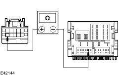
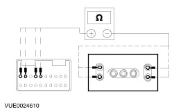
TEST the system for normal operation. No | | H3: CHECK RIGHT-HAND HEADPHONE CIRCUIT(S) FOR OPEN | | | 1 Disconnect Video System Module C1026. | | | 2 Disconnect Passenger Entertainment Control Panel C604. | | | 3 Measure the resistances between the video system module C1026 pin 1, circuit 2-MD11 (GY/WH), harness side and the passenger entertainment control panel C604 pin 2, circuit 2-MD11 (GY/WH), harness side; and between the video system module C1026 pin 4, circuit 2-MD18 (GY), harness side and the passenger entertainment control panel C604 pin 5, circuit 2-MD18 (GY), harness side. | | | Is the resistance less than 1 ohm? Yes No REPAIR the circuit(s) as necessary. TEST the system for normal operation | | H4: CHECK LEFT-HAND HEADPHONE CIRCUIT(S) FOR OPEN | | | 1 Disconnect Video System Module C1026. | | | 2 Disconnect Passenger Entertainment Control Panel C604. | | | 3 Measure the resistances between the video system module C1026 pin 2, circuit 1-MD11 (WH/VT), harness side and the passenger entertainment control panel C604 pin 1, circuit 1-MD11 (WH/VT), harness side; and between the video system module C1026 pin 5, circuit 1-MD18 (WH), harness side and the passenger entertainment control panel C604 pin 4, circuit 1-MD18 (WH), harness side. | | | Is the resistance less than 1 ohm? Yes No REPAIR the circuit(s) as necessary. TEST the system for normal operation | | H5: CHECK THE PASSENGER ENTERTAINMENT CONTROL PANEL FOR CONTINUITY | | | 1 Measure the resistance between the passenger entertainment control panel C604, component side and the headphone sockets: - pins 4 and 5 and the left-hand headphone sockets
- pins 1 and 2 and the right-hand headphone sockets
| | | Is the resistance less than 1 ohm? Yes INSTALL a new video system module.
REFER to: Video System Module - Vehicles Built From: 06/2003 (415-07 Video System, Removal and Installation).
TEST the system for normal operation. No INSTALL a new passenger entertainment control panel. TEST the system for normal operation. | | PINPOINT TEST I : THE VIDEO DISPLAY IS INOPERATIVE/DOES NOT OPERATE CORRECTLY | WARNING:Do not attempt to open or repair a video display as there are internal voltages in excess of 2000 volts. Failure to follow this instruction may result in personal injury. | | TEST CONDITIONS | DETAILS/RESULTS/ACTIONS | | I1: CHECK OPERATION OF THE VIDEO DISPLAY | | | 1 Change the head restraints/video displays between the two front seats. | | | Has the concern moved with the video display? Yes INSTALL a new head restraint/video display. TEST the system for normal operation. No For concern with right-hand video display, GO to I2. For concern with left-hand video display, GO to I8. | | I2: CHECK RIGHT-HAND FRONT SEAT BACKREST UPPER VIDEO SYSTEM C529 CIRCUIT 15-MD16A (GN/OG) FOR VOLTAGE | | | 1 Disconnect Right-Hand Front Seat Backrest Upper Video System C557. | | | 2 Measure the voltage between the right-hand front seat backrest upper video system C557 pin 6, circuit 15-MD16A (GN/OG), harness side and ground. | | | Is the voltage greater than 10 volts? Yes No | | I3: CHECK RIGHT-HAND FRONT SEAT BACKREST UPPER VIDEO SYSTEM C557 CIRCUIT 48-MD16A (NO) FOR GROUND | | | 1 Measure the resistance between the right-hand front seat backrest upper video system C557 pin 3, circuit 48-MD16A (NO), harness side and ground. | | | Is the resistance less than 1 ohm? Yes No REPAIR the circuit. TEST the system for normal operation. | | I4: CHECK POWER CIRCUIT BETWEEN RIGHT-HAND FRONT SEAT BACKREST UPPER VIDEO C557 (GN/OG) AND VIDEO SYSTEM MODULE C553 CIRCUIT 15-MD16A (GN/OG) FOR OPEN | | | 1 Disconnect Video System Module C553. | | | 2 Measure the resistance between the right-hand front seat backrest upper video system C557 pin 6, (GN/OG), harness side and the video system module C553 pin 6 (left-hand drive) or pin 16 (right-hand drive), circuit 15-MD16A (GN/OG), harness side. | | | Is the resistance less than 1 ohm? Yes No REPAIR the circuit (GN/OG). TEST the system for normal operation | | I5: CHECK RIGHT-HAND FRONT SEAT BACKREST UPPER VIDEO SYSTEM C557 CIRCUIT 15-XL1A (GN/BU) FOR ILLUMINATION VOLTAGE | | | 1 Measure the voltage between the right-hand front seat backrest upper video system C557 pin 12, circuit 15-XL1A (GN/BU), harness side and ground. | | | Is the voltage greater than 10 volts? Yes No | | I6: CHECK RIGHT-HAND FRONT SEAT BACKREST UPPER VIDEO SYSTEM C557 CIRCUIT 91-XL1A (BK/BU) FOR ILLUMINATION GROUND | | | 1 Measure the resistance between the right-hand front seat backrest upper video system C557 pin 9, circuit 91-XL1A (BK/BU), harness side and ground. | | | Is the resistance less than 1 ohm? Yes No REPAIR the circuit. TEST the system for normal operation. | | I7: CHECK CIRCUIT BETWEEN RIGHT-HAND FRONT SEAT BACKREST UPPER VIDEO SYSTEM C557 (GN/BU) AND VIDEO SYSTEM MODULE C553 CIRCUIT 15-XL1A (GN/BU) FOR OPEN | | | 1 Disconnect Video System Module C553. | | | 2 Measure the resistance between the right-hand front seat backrest upper video system C557 pin 12, (GN/BU), harness side and the video system module C553 pin 10 (left-hand drive) or pin 20 (right-hand drive), circuit 15-XL1A (GN/BU), harness side. | | | Is the resistance less than 1 ohm? Yes INSTALL a new video system module.
REFER to: Video System Module - Vehicles Built From: 06/2003 (415-07 Video System, Removal and Installation).
TEST the system for normal operation. No REPAIR the circuit. TEST the system for normal operation. | | I8: CHECK LEFT-HAND FRONT SEAT BACKREST UPPER VIDEO SYSTEM C554 CIRCUIT 16-MD16 (GN/OG) FOR VOLTAGE | | | 1 Disconnect Front Seat Backrest Upper Video System C554. | | | 2 Measure the voltage between the left-hand front seat backrest upper video system C554 pin 6, circuit 16-MD16 (GN/OG), harness side and ground. | | | Is the voltage greater than 10 volts? Yes No | | I9: CHECK LEFT-HAND FRONT SEAT BACKREST UPPER VIDEO SYSTEM C554 CIRCUIT 48-MD16 (NO) FOR GROUND | | | 1 Measure the resistance between the left-hand front seat backrest upper video system C554 pin 3, circuit 48-MD16 (NO), harness side and ground. | | | Is the resistance less than 1 ohm? Yes No REPAIR the circuit. TEST the system for normal operation. | | I10: CHECK POWER CIRCUIT BETWEEN LEFT-HAND FRONT SEAT BACKREST UPPER VIDEO C554 (GN/OG) AND VIDEO SYSTEM MODULE C553 CIRCUIT 16-MD16 (GN/OG) FOR OPEN | | | 1 Disconnect Video System Module C553. | | | 2 Measure the resistance between the left-hand front seat backrest upper video system C554 pin 6, (GN/OG), harness side and the video system module C553 pin 16 (left-hand drive) or pin 6 (right-hand drive), circuit 16-MD16 (GN/OG), harness side. | | | Is the resistance less than 1 ohm? Yes No REPAIR the circuit. TEST the system for normal operation. | | I11: CHECK LEFT-HAND FRONT SEAT BACKREST UPPER VIDEO SYSTEM C554 CIRCUIT 15-XL1 (GN/BU) FOR ILLUMINATION VOLTAGE | | | 1 Measure the voltage between the left-hand front seat backrest upper video system C554 pin 12, circuit 15-XL1 (GN/BU), harness side and ground. | | | Is the voltage greater than 10 volts? Yes No | | I12: CHECK LEFT-HAND FRONT SEAT BACKREST UPPER VIDEO SYSTEM C554 CIRCUIT 91-XL1 (WH/RD) FOR ILLUMINATION GROUND | | | 1 Measure the resistance between the left-hand front seat backrest upper video system C554 pin 9, circuit 91-XL1 (WH/RD), harness side and ground. | | | Is the resistance less than 1 ohm? Yes No REPAIR the circuit. TEST the system for normal operation. | | I13: CHECK CIRCUIT BETWEEN LEFT-HAND FRONT SEAT BACKREST UPPER VIDEO SYSTEM C554 (WH/RD) AND VIDEO SYSTEM MODULE C553 CIRCUIT 91-XL1 (WH/RD) FOR OPEN | | | 1 Disconnect Video System Module C553. | | | 2 Measure the resistance between the left-hand front seat backrest upper video system C554 pin 9, circuit 91-XL1 (WH/RD), harness side and the video system module C553 pin 19 (left-hand drive) or pin 9 (right-hand drive), circuit 91-XL1 (WH/RD), harness side. | | | Is the resistance less than 1 ohm? Yes INSTALL a new video system module.
REFER to: Video System Module - Vehicles Built From: 06/2003 (415-07 Video System, Removal and Installation).
TEST the system for normal operation. No REPAIR the circuit. TEST the system for normal operation. | | PINPOINT TEST J : THE DVD PLAYER IS INOPERATIVE/DOES NOT OPERATE CORRECTLY | | TEST CONDITIONS | DETAILS/RESULTS/ACTIONS | | J1: CHECK DVD PLAYER C556 CIRCUIT 31-MD4A (OG) FOR VOLTAGE | | | 1 Disconnect DVD Player C556. | | | 2 Switch the audio unit and video system ON. | | | 3 Measure the voltage between the DVD player C556 pin 4, circuit 31-MD4A (OG), harness side and ground. | | | Is the voltage greater than 10 volts? Yes No | | J2: CHECK DVD PLAYER C556 CIRCUIT 91-MD4A (BK/OG) FOR GROUND | | | 1 Measure the resistance between the DVD player C556 pin 8, circuit 91-MD4A (BK/OG), harness side and ground. | | | Is the resistance less than 1 ohm? Yes No REPAIR the circuit. TEST the system for normal operation. | | J3: CHECK SWITCHED POWER CIRCUIT TO THE VIDEO CASSETTE PLAYER C556 PIN 7 | | | 1 Ignition switch in position II. | | | 2 Measure the voltage between the DVD player C556 pin 7, harness side and ground. | | | Is the voltage greater than 10 volts? Yes INSTALL a new DVD player.
REFER to: Digital Versatile Disc (DVD) Player (415-07 Video System, Removal and Installation).
TEST the system for normal operation. No | | J4: CHECK POWER CIRCUIT BETWEEN VIDEO SYSTEM MODULE C552 CIRCUIT 31-MD4A (OG) AND DVD PLAYER C556 CIRCUIT 31-MD4A (OG) FOR OPEN | | | 1 Disconnect Video System Module C552. | | | 2 Measure the resistance between the video system module C552 pin 6, circuit 31-MD4A (OG), harness side and the DVD player C556 pin 4, circuit 31-MD4A (OG), harness side. | | | Is the resistance less than 1 ohm? Yes No REPAIR the circuit. TEST the system for normal operation. | | J5: CHECK SWITCHED POWER CIRCUIT BETWEEN THE VIDEO SYSTEM MODULE C552 PIN 3 AND THE DVD PLAYER C556 PIN 7 FOR OPEN | | | 1 Measure the resistance between the video system module C552 pin 3, harness side and the DVD player C556 pin 7, harness side. | | | Is the resistance less than 1 ohm? Yes INSTALL a new video system module.
REFER to: Video System Module - Vehicles Built From: 06/2003 (415-07 Video System, Removal and Installation).
TEST the system for normal operation. No REPAIR the circuit. TEST the system for normal operation. | | PINPOINT TEST K : THE REMOTE CONTROL IS INOPERATIVE/DOES NOT OPERATE CORRECTLY | | TEST CONDITIONS | DETAILS/RESULTS/ACTIONS | | K1: CHECK OPERATION OF THE INFRARED SENSORS USING THE REMOTE CONTROL | NOTE:Refer to the Multimedia System Operating Guide for full operating instructions. | | | 1 Operate the remote control while pointing it at the infrared sensor of each video display in turn. | | | 2 Change the head restraints/video displays between the two front seats. | | | Has the concern moved with the video display? Yes INSTALL a new head restraint/video display. TEST the system for normal operation. No For concern with right-hand video display, GO to K2. For concern with left-hand video display, GO to K3. | | K2: CHECK CIRCUIT BETWEEN RIGHT-HAND FRONT SEAT BACKREST UPPER VIDEO SYSTEM C557 (GY/BK) AND VIDEO SYSTEM MODULE C553 CIRCUIT 4-MD16A (GY/BK) FOR OPEN | | | 1 Disconnect Right-Hand Front Seat Backrest Upper Video System C557. | | | 2 Disconnect Video System Module C553. | | | 3 Measure the resistance between the right-hand front seat backrest upper video system C557 pin 4, 4-MD16A (GY/BK), harness side and the video system module C553 pin 4 (left-hand drive) or pin 14 (right-hand drive), circuit 4-MD16A (GY/BK), harness side. | | | Is the resistance less than 1 ohm? Yes No REPAIR the circuit. TEST the system for normal operation. | | K3: CHECK CIRCUIT BETWEEN LEFT-HAND FRONT SEAT BACKREST UPPER VIDEO SYSTEM C554 (GY/BK) AND VIDEO SYSTEM MODULE C553 CIRCUIT 4-MD16 (GY/BK) FOR OPEN | | | 1 Disconnect Front Seat Backrest Upper Video System C554. | | | 2 Disconnect Video System Module C553. | | | 3 Measure the resistance between the left-hand front seat backrest upper video system C554 pin 4, circuit 4-MD16 (GY/BK), harness side and the video system module C553 pin 14 (left-hand drive) or pin 4 (right-hand drive), circuit 4-MD16 (GY/BK), harness side. | | | Is the resistance less than 1 ohm? Yes No REPAIR the circuit. TEST the system for normal operation. | | K4: CHECK THE DVD PLAYER OPERATION USING THE CONTROLS ON THE DVD PLAYER | | | 1 Operate the DVD player using the controls on the DVD player. | | | Does the DVD player operate correctly? Yes INSTALL a new remote control. TEST the system for normal operation. No INSTALL a new video system module.
REFER to: Video System Module - Vehicles Built From: 06/2003 (415-07 Video System, Removal and Installation).
TEST the system for normal operation. | | PINPOINT TEST L : EXTERNAL GAME CONSOLE/MEDIA SOURCE IS INOPERATIVE/DOES NOT OPERATE CORRECTLY | WARNING:An inverter is required (not supplied by Ford) to convert the vehicle battery voltage to mains voltage to power external games consoles etc. Make sure the inverter cable has not become broken, split or damaged. Failure to follow this instruction may result in personal injury. | NOTE:Make sure that the external game console/media source device operates correctly out of the vehicle before commencing diagnostics. | | TEST CONDITIONS | DETAILS/RESULTS/ACTIONS | | L1: CHECK PASSENGER ENTERTAINMENT CONTROL PANEL C604 CIRCUIT 9-XL8 (BN/YE) FOR VIDEO GROUND | | | 1 Measure the resistance between the passenger entertainment control panel C604 pin 12, circuit 9-XL8 (BN/YE), harness side and ground. | | | Is the resistance less than 1 ohm? Yes No REPAIR the circuit. TEST the system for normal operation. | | L2: CHECK VIDEO CIRCUIT BETWEEN PASSENGER ENTERTAINMENT CONTROL PANEL C604 CIRCUIT 8-XL8 (WH/BK) AND VIDEO SYSTEM MODULE C520 (YE) | | | 1 Disconnect Video System Module C1026. | | | 2 Measure the resistance between the passenger entertainment control panel C604 pin 11 , circuit 8-XL8 (WH/BK), harness side and the video system module C1026 pin 7, circuit 8-XL8 (WH/BK), harness side. | | | Is the resistance less than 1 ohm? Yes No REPAIR the circuit. TEST the system for normal operation. | | L3: CHECK RIGHT-HAND AUDIO CIRCUIT BETWEEN PASSENGER ENTERTAINMENT CONTROL PANEL C604 CIRCUIT 2-MD16 (GY/BK) AND VIDEO SYSTEM MODULE C1026 CIRCUIT 2-MD16 (GY/BK) | | | 1 Measure the resistance between the passenger entertainment control panel C604 pin 13, circuit 2-MD16 (GY/BK), harness side and the video system module C1026 pin 9, circuit 2-MD16 (GY/BK), harness side. | | | Is the resistance less than 1 ohm? Yes No REPAIR the circuit. TEST the system for normal operation. | | L4: CHECK LEFT-HAND AUDIO CIRCUIT BETWEEN PASSENGER ENTERTAINMENT CONTROL PANEL C604 CIRCUIT 1-MD16 (WH/BK) AND VIDEO SYSTEM MODULE C1026 CIRCUIT 1-MD16 (WH/BK) | | | 1 Measure the resistance between the passenger entertainment control panel C604 pin 14, circuit 1-MD16 (WH/BK), harness side and the video system module C1026 pin 10, circuit 1-MD16 (WH/BK), harness side. | | | Is the resistance less than 1 ohm? Yes No REPAIR the circuit. TEST the system for normal operation. | | L5: CHECK THE PASSENGER ENTERTAINMENT CONTROL PANEL FOR CONTINUITY | | | 1 Measure the resistances between the passenger entertainment control panel C604, component side and the auxiliary input sockets: - pin 11 and the yellow video input socket center pin
- pin 12 and the yellow video input socket outer shield
- pin 13 and the red audio input socket center pin
- pin 14 and the white audio input socket center pin
- pin 15 and the red audio input socket outer shield
- pin 15 and the white audio input socket outer shield
| | | Are the resistances less than 1 ohm? Yes INSTALL a new video system module.
REFER to: Video System Module - Vehicles Built From: 06/2003 (415-07 Video System, Removal and Installation).
TEST the system for normal operation. No INSTALL a new passenger entertainment control panel. TEST the system for normal operation. | |