ford Workshop Repair Guides

Ford Workshop Service and Repair Manuals

General Procedures > < Roof Opening Panel
Roof Opening Panel - Roof Opening Panel Mondeo 2001 (10/2000-02/2007)
Diagnosis and Testing

Refer to Wiring Diagrams Section 501-17, for schematic and connector information.

Inspection and Verification

  1. Verify the customer concern.
  1. Visually inspect for obvious signs of mechanical or electrical damage.

Visual Inspection Chart

Mechanical Electrical
Roof opening panel Fuse(s)
Seal(s) Electrical connector(s)
Weatherstrip
Alignment
  1. If an obvious cause for an observed or reported concern is found, correct the cause (if possible) before proceeding to the next step.
  1. If the cause is not visually evident, verify the symptom and refer to the Symptom Chart.

Symptom Chart

Symptom Chart

Symptom Possible Sources Action
The roof opening panel leaks
*
Drain tubes.
*
CHECK the drain tubes for blockage or obstruction. CARRY OUT the Water Drainage System Check and Water Leak Corrections.
REFER to Water Drainage System Check and Water Leak Corrections in this section.
The roof opening panel rattles
*
Headliner.
*
CHECK the headliner for security. REFER to Section  501-05 Interior Trim and Ornamentation.
*
Guides and track.
*
Motor.
*
CHECK for worn or damaged components. CARRY OUT the Roof Opening Panel Alignment.
REFER to Roof Opening Panel Alignment in this section.
The roof opening panel is noisy during operation
*
Guides and track.
*
Motor.
*
CHECK for worn or damaged components. CARRY OUT the Roof Opening Panel Alignment.
REFER to Roof Opening Panel Alignment in this section.
The roof opening panel does not open or close
*
Switch.
*
CARRY OUT the Roof Opening Panel Control Switch Component Test in this procedure.
*
Motor.
*
CARRY OUT the Roof Opening Panel Motor Initialization.
REFER to Roof Opening Panel Motor Initialization in this section.
*
Circuits.
*
GO to Pinpoint Test A.
The roof opening panel shows unexpected bounce back at high speed.
*
Motor.
*
Circuits.
*
GO to Pinpoint Test B.
The roof opening panel does not stop in flush from any position
*
Guides and track.
*
Motor.
*
CHECK for worn or damaged components. CARRY OUT the Roof Opening Panel Alignment.
REFER to Roof Opening Panel Alignment in this section.

Pinpoint Tests

NOTE:
NOTE:Use a digital multimeter for all electrical measurements.

PINPOINT TEST A : THE ROOF OPENING PANEL DOES NOT OPEN OR CLOSE

TEST CONDITIONS DETAILS/RESULTS/ACTIONS
A1: CHECK FOR VOLTAGE TO THE ROOF OPENING PANEL CONTROL SWITCH
1
Ignition switch in position II.
2
CHECK the operation of the roof opening panel control switch lamp.

Does the roof opening panel control switch lamp illuminate?
Yes
No
A2: CHECK THE SUPPLY VOLTAGE TO THE ROOF OPENING PANEL CONTROL UNIT, CIRCUIT 29-AG12 (OG/BK)
1
Ignition switch in position 0.
2
Disconnect Fuse 73 (20A).
3
Disconnect Roof Opening Panel Control Unit C525.
4
Connect Fuse 73 (20A).
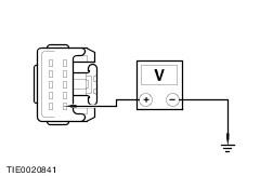
5
Measure the voltage between the roof opening panel control unit C525 pin 1, circuit 29-AG12 (OG/BK), harness side and ground.

Is the voltage greater than 10 volts?
Yes
No
REPAIR circuit 29-AG12 (OG/BK). TEST the system for normal operation.
A3: CHECK THE ROOF OPENING PANEL CONTROL SWITCH UP/CLOSE GROUND CIRCUIT
1
Operate the roof opening panel control switch to the UP/CLOSE position and keep it pressed.
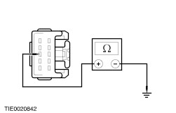
2
Measure the resistance between the roof opening panel control unit C525 pin 9, circuit 31S-AG7A (BK/BU), harness side and ground.

Is the resistance less than 100 ohms?
Yes
No
REPAIR circuit 31S-AG7A (BK/BU). TEST the system for normal operation.
A4: CHECK THE ROOF OPENING PANEL CONTROL SWITCH DOWN/OPEN GROUND CIRCUIT
1
Operate the roof opening panel control switch to the DOWN/OPEN position and keep it pressed.
2
Measure the resistance between the roof opening panel control unit C525 pin 8, circuit 31S-AG7 (BK/BU), harness side and ground.

Is the resistance less than 100 ohms?
Yes
No
REPAIR circuit 31S-AG7 (BK/BU). TEST the system for normal operation.
A5: CHECK THE ROOF OPENING PANEL CONTROL UNIT GROUND CIRCUIT
1
Measure the resistance between the roof opening panel control unit C525 pin 10, circuit 31-AG12 (BK), harness side and ground.

Is the resistance less than 5 ohms?
Yes
INSTALL a new roof opening panel control unit. TEST the system for normal operation.
No
REPAIR circuit 31-AG12 (BK). TEST the system for normal operation.
A6: CHECK THE SUPPLY VOLTAGE TO THE ROOF OPENING PANEL CONTROL SWITCH LAMP, CIRCUIT 15-AG7 (GN/BU)
1
Ignition switch in position 0.
2
Disconnect Roof Opening Panel Control Switch C522.
3
Ignition switch in position II.
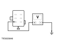
4
Measure the voltage between the roof opening panel control switch C522 pin 1, circuit 15-AG7 (GN/BU), harness side and ground.

Is the voltage greater than 10 volts?
Yes
No
REPAIR circuit 15-AG7 (GN/BU). TEST the system for normal operation.
A7: CHECK THE ROOF OPENING PANEL CONTROL SWITCH GROUND CIRCUIT
1
Ignition switch in position 0.
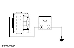
2
Measure the resistance between the roof opening panel control switch C522 pin 6, circuit 31-AG7 (BK), harness side and ground.

Is the resistance less than 5 ohms?
Yes
VERIFY the customer concern.
No
REPAIR circuit 31-AG7 (BK). TEST the system for normal operation.

PINPOINT TEST B : THE ROOF OPENING PANEL SHOWS UNEXPECTED BOUNCE BACK AT HIGH SPEED

TEST CONDITIONS DETAILS/RESULTS/ACTIONS
B1: CHECK THE OPERATION OF THE MULTIFUNCTION DISPLAY
1
Drive the vehicle.
2
Observe the multi-function display ‘Average speed’ function.

Does the display operate correctly?
Yes
No
REFER to Section  413-01 Instrument Cluster.
B2: CHECK FOR CONTINUITY BETWEEN THE POWERTRAIN CONTROL MODULE (PCM) AND THE ROOF OPENING PANEL CONTROL UNIT
1
Ignition switch in position 0.
2
Disconnect Roof Opening Panel Control Unit C525.
3
Ignition switch in position II.

4
Measure the voltage between the roof opening panel motor C525 pin 6, circuit 8-GB8 (WH/BU), harness side.

Is the voltage greater than 10 volts?
Yes
INSTALL a new roof opening panel motor.
REFER to Roof Opening Panel Motor - in this section.
TEST the system for normal operation.
No
REPAIR circuit 8-GB8 (WH/BU). TEST the system for normal operation.

Component Tests

Roof Opening Panel Control Switch

  1. Measure the resistance between the following:
Roof Opening Panel Control Switch Position Terminals Measurements
Neutral 1 - 6 GO to Step 2.
Neutral 1 - 2 Greater than 10,000 ohms
Neutral 1 - 5 Greater than 10,000 ohms
Neutral 2 - 6 Greater than 10,000 ohms
Neutral 5 - 6 Greater than 10,000 ohms
Neutral 6 - 1 Greater than 10,000 ohms
Fully Up/Close 5 - 1 Greater than 10,000 ohms
Fully Up/Close 5 - 6 Less than 100 ohms
Fully Up/Close 5 - 2 Less than 100 ohms
Fully Up/Close 2 - 6 Less than 100 ohms
Fully Down/Open 2 - 6 Less than 100 ohms
Fully Down/Open 2 - 5 Less than 100 ohms
Fully Down/Open 5 - 6 Less than 100 ohms
Fully Down/Open 2 - 1 Greater than 10,000 ohms
  1. Using suitable leads, connect the roof opening panel control switch C522 pin 1 to the battery positive terminal and the roof opening panel control switch C522 pin 6 to the battery negative terminal. The LED should illuminate. If the LED does not illuminate install a new roof opening panel control switch.
  1. If the roof opening panel control switch values are as specified, return to the Pinpoint Test. If the roof opening panel control switch values are outside the specified values, install a new roof opening panel control switch.

General Procedures > < Roof Opening Panel