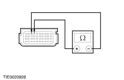
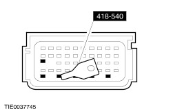
| Diagnosis and Testing Refer to Wiring Diagrams Section 501-20B, for schematic and connector information. Special Tool(s) | | Test and Deployment Lead, Air Bag/Pyrotechnic Safety Belt 418–S055 | | | Test and Deployment Lead - Side Air Curtain Module 418–141 | | | Test and Deployment Lead - Driver; Passenger and Side Air Bag Module 418–525 | | | Deactivator, Shorting Bar 418–540 | | | Simulator, Air Bag 501–073A | | | Diagnostic Simulator Set, Occupant Restraint 501–077 | General Equipment Worldwide diagnostic system (WDS) Diagnosing Customer Concerns Without Hard DTCs/LFCs WARNING:The back up power supply must be depleted, before any work is carried out on the supplemental restraint system. Wait at least one minute after disconnecting the battery ground cable. Failure to follow this instruction may result in personal injury. NOTE:Following the pinpoint tests when a diagnostic trouble code/lamp fault code (DTC/LFC) is not present, will result in needless replacement of air bag system components and repeat repairs. Speak with the customer to determine if a particular set of conditions must be met in order for a fault to occur. If a LFC is reported by the customer but is not present when the vehicle comes in for repair, pinpoint test diagnostics cannot be used. Instruct the customer on how to count a LFC. Diagnosing Customer Concerns with Hard DTCs/LFCs WARNING:Do not use substitute air bag simulators when working on the supplemental restraint system. Use only the appropriate tool. Failure to follow this instruction may result in personal injury. Most air bag system diagnostic procedures require the use of system deactivation and system reactivation procedures. These procedures require the air bag module(s) and safety belt buckle pretensioners to be disconnected from the SRS, thereby removing the risk of air bag deployment while diagnostics are carried out. Air bag simulators are required to carry out diagnosis and testing of the air bag system. The simulator contains a resistor, used to simulate an air bag module connection to the system. It is not acceptable to short-circuit the air bag module connections with a 0 ohm jumper wire. If a 0 ohm jumper wire is used to short-circuit the air bag module connections, a LFC will be displayed and a DTC logged by the air bag control module. Deactivation WARNING:The back up power supply must be depleted, before any work is carried out on the supplemental restraint system. Wait at least one minute after disconnecting the battery ground cable. Failure to follow this instruction may result in personal injury. NOTE:When the passenger underseat simulator is installed on vehicles equipped with the occupant classification system, the passenger air bag deactivation (PAD) indicator will illuminate continuously when the ignition is turned to the RUN position, provided the seat is empty. The simulator is designed to simulate an empty seat and a fastened passenger safety belt buckle. - Disconnect the battery ground cable.
REFER to: Battery Disconnect and Connect (414-01 Battery, Mounting and Cables, General Procedures).
- Wait at least one minute for the backup power supply in the air bag control module to deplete its stored energy.
WARNING:Place the air bag module on a ground wired bench, with the trim cover facing up to avoid accidental deployment. Failure to follow this instruction may result in personal injury. - Remove the driver air bag module from the vehicle.
REFER to: Driver Air Bag Module (501-20B Supplemental Restraint System, Removal and Installation).
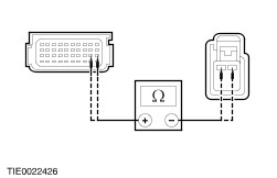
- Connect the air bag simulators to the sub-harnesses in place of the driver air bag module at the top of the steering column.
- Disconnect the passenger air bag module electrical connectors.
REFER to: Passenger Air Bag Module (501-20B Supplemental Restraint System, Removal and Installation).
- Connect the air bag simulators to the wiring harnesses in place of the passenger air bag module.
- Disconnect both side air curtain module electrical connectors.
REFER to: Side Air Curtain Module - 4-Door (501-20B Supplemental Restraint System, Removal and Installation) /
Side Air Curtain Module - 5-Door (501-20B Supplemental Restraint System, Removal and Installation) /
Side Air Curtain Module - Wagon (501-20B Supplemental Restraint System, Removal and Installation).
- Connect the air bag simulators to the wiring harnesses in place of the side air curtain modules.
- Disconnect the driver underseat air bag electrical connector.
- Connect the driver underseat air bag simulator to the floor harness.
- Disconnect the passenger underseat air bag electrical connector.
- Connect the passenger underseat air bag simulator between the floor harness electrical connector and the passenger seat harness electrical connector.
- Connect the battery ground cable.
REFER to: Battery Disconnect and Connect (414-01 Battery, Mounting and Cables, General Procedures).
Reactivation WARNING:The air bag simulators must be removed and the air bag modules reconnected when reactivated to avoid non-deployment in a collision. Failure to follow this instruction may result in personal injury. - Disconnect the battery ground cable.
REFER to: Battery Disconnect and Connect (414-01 Battery, Mounting and Cables, General Procedures).
- Wait at least one minute for the backup power supply in the air bag control module to deplete its stored energy.
- Remove the driver air bag simulators from the sub-harness at the top of the steering column.
- Connect and install the driver air bag module.
REFER to: Driver Air Bag Module (501-20B Supplemental Restraint System, Removal and Installation).
- Remove the passenger air bag simulators from the passenger air bag module wiring harnesses.
- Connect and install the passenger air bag module.
REFER to: Passenger Air Bag Module (501-20B Supplemental Restraint System, Removal and Installation).
- Remove the side air curtain simulators from the side air curtain module wiring harnesses.
- Connect and install the side air curtain modules.
REFER to: Side Air Curtain Module - 4-Door (501-20B Supplemental Restraint System, Removal and Installation) /
Side Air Curtain Module - 5-Door (501-20B Supplemental Restraint System, Removal and Installation) /
Side Air Curtain Module - Wagon (501-20B Supplemental Restraint System, Removal and Installation).
- Remove the driver underseat air bag simulator.
- Connect the driver underseat air bag electrical connector.
- Remove the passenger underseat air bag simulator.
- Connect the passenger underseat air bag electrical connector.
- Connect the battery ground cable.
REFER to: Battery Disconnect and Connect (414-01 Battery, Mounting and Cables, General Procedures).
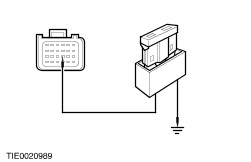
Glossary Air Bag Simulator Air bag simulators are used to simulate air bag module connections to the system. Deactivate the System Deactivate the system means to carry out the deactivation procedure. Prove Out the System The air bag warning indicator will illuminate for six seconds. If a fault is detected the indicator flashes a corresponding fault code five times and then remains illuminated continuously. Reactivate the System Reactivate the system means to carry out the reactivation procedure. Principles of Operation Supplemental Restraint System (SRS) Operation The vehicle is equipped with a DC fired sensing system. Air bag deployment will only occur, in the event of a severe collision when the ignition key is in the RUN position. Air Bag Control Module The air bag control module retains full control of the whole system, providing continual system checks and full diagnostic capabilities. The non-volatile memory stores the fault codes, which are down loaded through the diagnostic link connector to WDS. In the event of a failure in the vehicle power supply during an accident, the air bag control module provides an auxiliary power supply, sufficient to deploy the front air bag(s) for a minimum of 150mS. The auxiliary power supply is discharged by the air bag control within 60 seconds of the battery ground cable being disconnected. Thus making sure the supplemental restraint system remains operational. The air bag control module contains a microcontroller to evaluate and process impact data. The front crash sensor discriminates frontal impacts and provides information on the severity of the impact to the air bag control module. The side impact sensors discriminates lateral impacts and provides information on the severity of the impact to the air bag control module. The air bag control module will initiate the deployment of the appropriate air bags as soon as an impact of sufficient severity is detected. Air Bag Control Module Wiring Harness Connectors 1 - Connector shorting bar positions Both air bag control module connectors have shorting bars on the harness side for air bag circuits. Pin numbers remain constant where pin positions have been removed due to the shorting bars. Crash Sensor and Side Impact Sensors Both the crash sensor and the side impact sensors contain an acceleration sensor, filter, amplifier and an application specific integrated circuit for signal transmitting. In the event of a collision, in excess of a predetermined limit, the crash sensor or a side impact sensor will initiate a deployment request to the air bag control module. The signal received by the air bag control module is evaluated and processed against stored data. The crash sensor and the side impact sensors do not process the impact data. Air Bag Warning Indicator The air bag warning indicator is incorporated into the instrument cluster, together with the automatic detach detect (ADD) circuit. The air bag warning indicator illuminates for six seconds at key ON. If the system self-tests OK the indicator extinguishes, if a fault is detected the indicator flashes a corresponding fault code five times and then remains illuminate continuously. The ADD circuit is designed to illuminate the air bag warning indicator continuously, if the air bag control module circuit is broken, either by loss of power or ground supply or electrical connector disconnection. Diagnostic evaluation of the supplemental restraints system can be made through the data link connector (DLC) and WDS to establish the nature of the concern. Once the DTC is known the appropriate course of action can be selected from the Symptom Chart. Inspection and Verification - Verify the customer concern by operating the system.
- Visually inspect for obvious signs of mechanical or electrical damage.
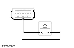
Visual Inspection Chart | Electrical | | Fuse(s) | | Electrical connector(s) | | Circuit(s) | | Wiring harness | | Air bag module(s) | | Bulb | - If an obvious cause for an observed or reported concern is found, correct the cause (if possible) before proceeding to the next step.
- If the cause is not visually evident, connect the diagnostic tool to the data link connector and select the vehicle to be tested from the diagnostic tool menu.
- Retrieve the DTCs and REFER to the Symptom Chart.
Symptom Chart Symptom Chart | Symptom | Possible Sources | Action | | No communication with the module | * Fuse. * DLC. * Circuit(s). * Air bag control module. | * | | DTC B1231: Longitudinal acceleration threshold exceeded. Lamp flash code: 13 | * Crash data memory full. | * Data cannot be cleared with WDS. INSTALL a new air bag control module.
REFER to: Air Bag Control Module (501-20B Supplemental Restraint System, Removal and Installation).
REPEAT the self-test, CLEAR the DTCs. | | DTC B1317: Battery voltage high. Lamp flash code: continuous | * Charging system. | * Check the charging system.
REFER to: Battery Charging (414-00 Charging System - General Information, General Procedures).
REPEAT the self-test, CLEAR the DTCs. | | DTC B1318: Battery voltage low. Lamp flash code: continuous | * Battery. * Charging system. * Circuit. | * | | DTC B1342: Air bag control module is defective. Lamp flash code: 12 | * Air bag control module. | * INSTALL a new air bag control module.
REFER to: Air Bag Control Module (501-20B Supplemental Restraint System, Removal and Installation).
REPEAT the self-test, CLEAR the DTCs. | | DTC B1869: Air bag warning indicator open circuit or short to ground. Lamp flash code: continuous | * Circuit(s). * Instrument cluster. * Air bag control module. | * | | DTC B1870: Air bag warning indicator short to battery. Lamp flash code: continuous | * Circuit. * Instrument cluster. | * | | DTC 1884: Passenger air bag deactivation indicator inoperative. Lamp flash code: 18 | * Circuit(s). * Air bag control module. * Passenger air bag deactivation indicator. | * | | DTC B1890: Passenger air bag deactivation indicator short to battery. Lamp flash code: 18 | * Circuit(s). * Passenger air bag deactivation indicator. | * | | DTC B1891: Air bag tone warning indicator short to battery. Lamp flash code: 53 | * Air bag control module internal fault. | * INSTALL a new air bag control module.
REFER to: Air Bag Control Module (501-20B Supplemental Restraint System, Removal and Installation).
REPEAT the self-test, CLEAR the DTCs. | | DTC B1892: Air bag tone warning indicator circuit fault. Lamp flash code: 53 | * Air bag control module internal fault. | * INSTALL a new air bag control module.
REFER to: Air Bag Control Module (501-20B Supplemental Restraint System, Removal and Installation).
REPEAT the self-test, CLEAR the DTCs. | | DTC B1921: Air bag diagnostic monitor ground circuit open. Lamp flash code: 14 | * Air bag control module internal fault. | * INSTALL a new air bag control module.
REFER to: Air Bag Control Module (501-20B Supplemental Restraint System, Removal and Installation).
REPEAT the self-test, CLEAR the DTCs. | | DTC B2290 Error value 27: Occupant Classification System module fault. Lamp flash code: 16 | * Occupant classification sensor module. | * INSTALL a new passenger seat cushion.
REFER to: Front Seat Cushion - Vehicles Without: Climate Controlled Seats (501-10 Seating, Removal and Installation).
REPEAT the self-test, CLEAR the DTCs. | | DTC B2290 Error value 26: Occupant Classification System communications fault. Lamp flash code: 16 | * Circuit(s). | * | | DTC B2290 Error value 25: Occupant Classification System calibration fault. Lamp flash code: 16 | * Occupant classification sensor module. | * INSTALL a new passenger seat cushion.
REFER to: Front Seat Cushion - Vehicles Without: Climate Controlled Seats (501-10 Seating, Removal and Installation).
REPEAT the self-test, CLEAR the DTCs. | | DTC B2290 Error value 24: Occupant Classification System sensing element fault. Lamp flash code: 16 | * Occupant classification sensor. | * INSTALL a new passenger seat cushion.
REFER to: Front Seat Cushion - Vehicles Without: Climate Controlled Seats (501-10 Seating, Removal and Installation).
REPEAT the self-test, CLEAR the DTCs. | | DTC B2292 Error value 31: Driver safety belt pretensioner circuit low resistance. Lamp flash code: 33 | * Circuit(s). * Driver safety belt pretensioner. | * | | DTC B2292 Error value 30: Driver safety belt pretensioner open circuit. Lamp flash code: 33 | * Circuit(s). * Driver safety belt pretensioner. | * | | DTC B2292 Error value 29: Driver safety belt pretensioner short to battery. Lamp flash code: 33 | * Circuit(s). | * | | DTC B2292 Error value 28: Driver safety belt pretensioner short to ground. Lamp flash code: 33 | * Circuit(s). * Driver safety belt pretensioner. | * | | DTC B2292 Error value 27: Passenger safety belt pretensioner circuit low resistance. Lamp flash code: 34 | * Circuit(s). * Passenger safety belt pretensioner. | * | | DTC B2292 Error value 26: Passenger safety belt pretensioner open circuit. Lamp flash code: 34 | * Circuit(s). * Passenger safety belt pretensioner. | * | | DTC B2292 Error value 25: Passenger safety belt pretensioner short to battery. Lamp flash code: 34 | * Circuit(s). * Passenger safety belt pretensioner. | * | | DTC B2292 Error value 24: Passenger safety belt pretensioner short to ground. Lamp flash code: 34 | * Circuit(s). * Passenger safety belt pretensioner. | * | | DTC B2293 Error value 31: Driver air bag first stage short to ground. Lamp flash code: 19 | * Driver air bag module. * Clockspring. * Circuit(s). | * | | DTC B2293 Error value 30: Driver air bag first stage short to battery. Lamp flash code: 19 | * Clockspring. * Circuit(s). | * | | DTC B2293 Error value 29: Driver air bag first stage open circuit. Lamp flash code: 19 | * Driver air bag module. * Clockspring. * Circuit(s). | * | | DTC B2293 Error value 28: Driver air bag first stage circuit low resistance. Lamp flash code: 19 | * Driver air bag module. * Clockspring. * Circuit(s). | * | | DTC B2293 Error value 27: Passenger air bag first stage short to ground. Lamp flash code: 21 | * Passenger air bag module. * Circuit(s). | * | | DTC B2293 Error value 26: Passenger air bag first stage short to battery. Lamp flash code: 21 | * Circuit(s). | * | | DTC B2293 Error value 25: Passenger air bag first stage open circuit. Lamp flash code: 21 | * Passenger air bag module. * Circuit(s). | * | | DTC B2293 Error value 24: Passenger air bag first stage circuit low resistance. Lamp flash code: 21 | * Passenger air bag module. * Circuit(s). | * | | DTC B2293 Error value 23: Driver air bag second stage short to ground. Lamp flash code: 19 | * Driver air bag module. * Clockspring. * Circuit(s). | * | | DTC B2293 Error value 22: Driver air bag second stage short to battery. Lamp flash code: 19 | * Clockspring. * Circuit(s). | * | | DTC B2293 Error value 21: Driver air bag second stage open circuit. Lamp flash code: 19 | * Driver air bag module. * Clockspring. * Circuit(s). | * | | DTC B2293 Error value 20: Driver air bag second stage circuit low resistance. Lamp flash code: 19 | * Driver air bag module. * Clockspring. * Circuit(s). | * | | DTC B2293 Error value 19: Passenger air bag second stage short to ground. Lamp flash code: 21 | * Passenger air bag module. * Circuit(s). | * | | DTC B2293 Error value 18: Passenger air bag second stage short to battery. Lamp flash code: 21 | * Circuit(s). | * | | DTC B2293 Error value 17: Passenger air bag second stage open circuit. Lamp flash code: 21 | * Passenger air bag module. * Circuit(s). | * | | DTC B2293 Error value 16: Passenger air bag second stage circuit low resistance. Lamp flash code: 21 | * Passenger air bag module. * Circuit(s). | * | | DTC B2294 Error value 31: Driver side air curtain circuit short to battery. Lamp flash code: 24 | * Circuit(s). | * | | DTC B2294 Error value 30: Driver side air curtain circuit short to ground. Lamp flash code: 24 | * Driver side air curtain module. * Circuit(s). | * | | DTC B2294 Error value 29: Driver side air curtain circuit open circuit. Lamp flash code: 24 | * Driver side air curtain module. * Circuit(s). | * | | DTC B2294 Error value 28: Driver side air curtain circuit low resistance on squib. Lamp flash code: 24 | * Driver side air curtain module. * Circuit(s). | * | | DTC B2294 Error value 27: Passenger side air curtain circuit short to battery. Lamp flash code: 25 | * Circuit(s). | * | | DTC B2294 Error value 26: Passenger side air curtain circuit short to ground. Lamp flash code: 25 | * Passenger side air curtain module. * Circuit(s). | * | | DTC B2294 Error value 25: Passenger side air curtain circuit open circuit. Lamp flash code: 25 | * Passenger side air curtain module. * Circuit(s). | * | | DTC B2294 Error value 24: Passenger side air curtain circuit low resistance on squib. Lamp flash code: 25 | * Passenger side air curtain module. * Circuit(s). | * | | DTC B2295 Error value 31: Driver side air bag circuit short to battery. Lamp flash code: 22 | * Circuit(s). | * | | DTC B2295 Error value 30: Driver side air bag circuit short to ground. Lamp flash code: 22 | * Driver side air bag module. * Circuit(s). | * | | DTC B2295 Error value 29: Driver side air bag circuit open circuit. Lamp flash code: 22 | * Driver side air bag module. * Circuit(s). | * | | DTC B2295 Error value 28: Driver side air bag circuit low resistance on squib. Lamp flash code: 22 | * Driver side air bag module. * Circuit(s). | * | | DTC B2295 Error value 27: Passenger side air bag circuit short to battery. Lamp flash code: 23 | * Circuit(s). | * | | DTC B2295 Error value 26: Passenger side air bag circuit short to ground. Lamp flash code: 23 | * Passenger side air bag module. * Circuit(s). | * | | DTC B2295 Error value 25: Passenger side air bag circuit open circuit. Lamp flash code: 23 | * Passenger side air bag module. * Circuit(s). | * | | DTC B2295 Error value 24: Passenger side air bag circuit low resistance on squib. Lamp flash code: 23 | * Passenger side air bag module. * Circuit(s). | * | | DTC B2296 Error value 31: Driver side impact sensor communications fault. Lamp flash code: 43 | * Circuit(s). | * | | DTC B2296 Error value 30: Driver side impact sensor internal fault. Lamp flash code: 43 | * Driver side impact sensor. | * INSTALL a new driver side impact sensor.
REFER to: Side Impact Sensor (501-20B Supplemental Restraint System, Removal and Installation).
REPEAT the self-test, CLEAR the DTCs. | | DTC B2296 Error value 29: Passenger side impact sensor communications fault. Lamp flash code: 44 | * Circuit(s). | * | | DTC B2296 Error value 28: Passenger side impact sensor internal fault. Lamp flash code: 44 | * Passenger side impact sensor. | * INSTALL a new passenger side impact sensor.
REFER to: Side Impact Sensor (501-20B Supplemental Restraint System, Removal and Installation).
REPEAT the self-test, CLEAR the DTCs. | | DTC B2296 Error value 19: Crash sensor communications fault. Lamp flash code: 42 | * Circuit(s). | * | | DTC B2296 Error value 18: Crash sensor internal fault. Lamp flash code: 42 | * Crash sensor. | * INSTALL a new crash sensor.
REFER to: Crash Sensor (501-20B Supplemental Restraint System, Removal and Installation).
REPEAT the self-test, CLEAR the DTCs. | | DTC B2434: Driver safety belt buckle switch short circuit to ground. Lamp flash code: 51 | * Driver safety belt buckle switch. * Circuit(s). | * | | DTC B2435: Driver safety belt buckle switch resistance out of range. Lamp flash code: 51 | * Driver safety belt buckle switch. * Circuit(s). | * | | DTC B2438: Passenger safety belt buckle switch short circuit to ground. Lamp flash code: 52 | * Passenger safety belt buckle switch. * Circuit(s). | * | | DTC B2439: Passenger safety belt buckle switch resistance out of range. Lamp flash code: 52 | * Passenger safety belt buckle switch. * Circuit(s). | * | | DTC B2477: Air bag control module configuration failure. Lamp flash code: 54 | * Air bag control module. | * CONFIGURE the air bag control module. REFER to WDS. REPEAT the self-test, CLEAR the DTCs. | | DTC B2691: Driver safety belt buckle switch open circuit or short to battery. Lamp flash code: 51 | * Driver safety belt buckle switch. * Circuit(s). | * | | DTC B2692: Passenger safety belt buckle switch open circuit short to battery. Lamp flash code: 52 | * Passenger safety belt buckle switch. * Circuit(s). | * | | DTC C1414: Incorrect Module Design Level. Lamp flash code: 15 | * Air bag control module. | * INSTALL a new air bag control module.
REFER to: Air Bag Control Module (501-20B Supplemental Restraint System, Removal and Installation).
REPEAT the self-test, CLEAR the DTCs. | | DTC C1947: Seat position sensor short circuit to ground or battery. Lamp flash code: 49 | * Seat position sensor. * Circuit(s). | * | | DTC C1948: Seat position sensor resistance out of range. Lamp flash code: 49 | * Seat position sensor. * Circuit(s). | * | | DTC C1981: Seat position sensor open circuit. Lamp flash code: 49 | * Seat position sensor. * Circuit(s). | * | | Air bag control module disconnected or inoperative. Lamp flash code: continuous | * Air bag control module * Circuit(s). | * | Pinpoint Tests | PINPOINT TEST A : NO COMMUNICATION WITH THE MODULE | WARNING:Wait at least one minute after disconnecting the battery ground cable before disconnecting any supplemental restraint system electrical connector. Failure to follow this instruction may result in personal injury. | | TEST CONDITIONS | DETAILS/RESULTS/ACTIONS | | A1: CHECK THE WDS IS COMMUNICATING THROUGH THE DATA LINK CONNECTOR (DLC) | | | 1 Select an alternative system to check the DLC. | | | Is WDS able to communicate with the selected system? Yes No CHECK the DLC. For additional information, REFER to the Wiring Diagrams. | | A2: CHECK THE AIR BAG WARNING INDICATOR | | | 1 Ignition switch in position II. | | | 2 The air bag warning indicator should illuminate when the ignition is in the ON position for six seconds and then go out. If a fault is present, the air bag warning light will then begin to flash. | | | Is the warning indicator operating? Yes No CHECK the instrument cluster.
REFER to: Instrument Cluster (413-01 Instrument Cluster, Diagnosis and Testing).
| | A3: CHECK THE DLC CIRCUIT | | | 1 Ignition switch in position 0. | | | 2 Deactivate the supplemental restraint system. | | | 3 Disconnect Air Bag Control Module C490. | | | 4 Measure the resistance between the DLC C418 pin 7, circuit 8-EE10 (WH/BK) and the air bag control module C490 pin 11, circuit 8-EE7 (WH/RD) harness side. | | | Is the resistance less than 5 ohms? Yes If the air bag warning indicator is flashing, count the lamp flash code and REFER to the Symptom Chart in this section. INSTALL a new air bag control module.
REFER to: Air Bag Control Module (501-20B Supplemental Restraint System, Removal and Installation).
REACTIVATE the system. No REPAIR circuit 8-EE7 (WH/RD) or 8-EE10 (WH/BK). REPEAT the self-test, CLEAR the DTCs. REACTIVATE the system. | | PINPOINT TEST B : DTC B1318: BATTERY VOLTAGE LOW | WARNING:To avoid accidental deployment, the air bag control module backup power supply must be depleted. Wait at least one minute after disconnecting the battery ground cable(s) before commencing any repair or adjustment to the supplemental restraint system (SRS), or any component(s) adjacent to the SRS sensors. Failure to follow these instructions may result in personal injury. | | TEST CONDITIONS | DETAILS/RESULTS/ACTIONS | | B1: CHECK THE BATTERY VOLTAGE | | | 1 Ignition switch in position II. | | | 2 Check the battery voltage with the ignition in the ON position. | | | Is the battery voltage greater than 8 volts? Yes No CHECK the battery and charging system.
REFER to: Charging System (414-00 Charging System - General Information, Diagnosis and Testing).
REPEAT the self-test CLEAR the DTCs. | | B2: CHECK THE RESTRAINTS CONTROL MODULE SUPPLY CIRCUIT | | | 1 Ignition switch in position 0. | | | 2 Deactivate the supplemental restraint system. | | | 3 Disconnect Restraints Control Module C424. | | | 4 Ignition switch in position II. | | | 5 Measure the voltage between the restraints control module C490 pin 12, circuit 15-JA10 (GN/OG), harness side. | | | Is the voltage greater than 10 volts? Yes No REPAIR circuit 15-JA10 (GN/OG). REPEAT the self-test. CLEAR the DTCs. REACTIVATE the system. | | B3: CHECK THE RESTRAINTS CONTROL MODULE SUPPLY CIRCUIT | | | 1 Disconnect Fuse 89. | | | 2 Measure the resistance between the restraints control module C424 pin 12, circuit 15-JA10 (GN/OG), harness side and fuse 89, harness side. | | | Is the resistance less than 5 ohms? Yes REPEAT the self-test, CLEAR the DTCs. REACTIVATE the system. No REPAIR circuit 15-JA10 (GN/OG). REPEAT the self-test, CLEAR the DTCs. REACTIVATE the system. | | PINPOINT TEST C : DTC B1869: AIR BAG WARNING INDICATOR OPEN CIRCUIT OR SHORT TO GROUND | | TEST CONDITIONS | DETAILS/RESULTS/ACTIONS | | C1: CHECK THE AIR BAG WARNING INDICATOR | | | 1 Ignition switch in position II. | | | 2 Check the air bag warning indicator. | | | Is the air bag warning indicator illuminated continuously? Yes No | | C2: CHECK THE AIR BAG WARNING INDICATOR CIRCUIT | WARNING:Wait at least one minute after disconnecting the battery ground cable before disconnecting any supplemental restraint system electrical connector. Failure to follow this instruction may result in personal injury. | | | 1 Ignition switch in position 0. | | | 2 Deactivate the supplemental restraint system. | | | 3 Disconnect Air Bag Control Module C490. | | | 4 Disconnect Instrument Cluster C449. | | | 5 Measure the resistance between the instrument cluster C449 pin 9, circuit 91S-JA14 (BK/GN) and the air bag control module C490 pin 19, circuit 91S-JA14 (BK/GN). | | | Is the resistance less than 5 ohms? Yes No REPAIR circuit 91S-JA14 (BK/GN). REPEAT the self-test, CLEAR the DTCs. REACTIVATE the system. | | C3: CHECK THE AIR BAG WARNING INDICATOR FUNCTION | | | 1 Connect Instrument Cluster C449. | | | 2 Install a fused (7.5A) jumper wire between the air bag control module C490 pin 19, circuit 91S-JA14 (BK/GN) harness side and ground, turn the ignition to the ON position. | | | Is the air bag warning indicator illuminated? Yes INSTALL a new instrument cluster.
REFER to: Instrument Cluster (413-01 Instrument Cluster, Removal and Installation).
REPEAT the self-test, CLEAR the DTCs. REACTIVATE the system. No | | C4: CHECK THE INSTRUMENT CLUSTER WARNING INDICATORS | WARNING:Wait at least one minute after disconnecting the battery ground cable before disconnecting any supplemental restraint system electrical connector. Failure to follow this instruction may result in personal injury. | | | 1 Deactivate the supplemental restraint system. | | | 2 Ignition switch in position II. | | | 3 Check the instrument cluster warning indicators. | | | Are the warning indicators illuminated when the ignition is switched to the ON position? Yes No CHECK the instrument cluster.
REFER to: Instrument Cluster (413-01 Instrument Cluster, Diagnosis and Testing).
| | C5: CHECK THE AIR BAG WARNING INDICATOR FUNCTION | | | 1 With the fused (7.5A) jumper wire between the air bag control module C490 pin 19, circuit 91S-JA14 (BK/GN) harness side and ground, disconnect the fused jumper wire from the ground. | | | Is the air bag warning indicator illuminated? Yes INSTALL a new air bag control module.
REFER to: Air Bag Control Module (501-20B Supplemental Restraint System, Removal and Installation).
REPEAT the self-test, CLEAR the DTCs. REACTIVATE the system. No REPEAT the self-test, CLEAR the DTCs. REACTIVATE the system. | | C6: CHECK THE AIR BAG WARNING INDICATOR CIRCUIT | | | 1 Ignition switch in position 0. | | | 2 Disconnect Air Bag Control Module C490. | | | 3 Measure the resistance between the air bag control module C490 pin 19, circuit 91S-JA14 (BK/GN) harness side and ground. | | | Is the resistance greater than 10,000 ohms? Yes CHECK the air bag warning indicator LED. REPEAT the self-test, CLEAR the DTCs. REACTIVATE the system. No REPAIR circuit 91S-JA14 (BK/GN). REPEAT the self-test, CLEAR the DTCs. REACTIVATE the system. | | PINPOINT TEST D : DTC B1870: AIR BAG WARNING INDICATOR SHORT TO BATTERY | WARNING:Wait at least one minute after disconnecting the battery ground cable before disconnecting any supplemental restraint system electrical connector. Failure to follow this instruction may result in personal injury. | | TEST CONDITIONS | DETAILS/RESULTS/ACTIONS | | D1: CHECK THE AIR BAG WARNING INDICATOR | | | 1 Deactivate the supplemental restraint system. | | | 2 Disconnect Air Bag Control Module C490. | | | 3 Disconnect Instrument Cluster C449. | | | 4 Ignition switch in position II. | | | 5 Measure the voltage between the air bag control module C490 pin 19, circuit 91S-JA14 (BK/GN) harness side and ground. | | | Is any voltage present? Yes REPAIR the air bag wiring harness. For additional information, REFER to the Wiring Diagrams. REPEAT the self-test, CLEAR the DTCs. REACTIVATE the system. No CHECK the instrument cluster.
REFER to: Instrument Cluster (413-01 Instrument Cluster, Diagnosis and Testing).
REPEAT the self-test, CLEAR the DTCs. REACTIVATE the system. | | PINPOINT TEST E : DTC B1884: PASSENGER AIR BAG DEACTIVATION (PAD) INDICATOR INOPERATIVE | WARNING:Wait at least one minute after disconnecting the battery ground cable before disconnecting any supplemental restraint system electrical connector. Failure to follow this instruction may result in personal injury. | | TEST CONDITIONS | DETAILS/RESULTS/ACTIONS | | E1: CHECK THE PAD INDICATOR FUNCTION | | | 1 Deactivate the supplemental restraint system. | | | 2 Disconnect Air Bag Control Module C490. | | | 3 Using the special tool, disable the shorting bar on C490 pin 15. | | | 4 Install a fused (7.5A) jumper wire between the air bag control module C490 pin 15, circuit 91S-JA47 (BK/OG) harness side and ground, turn the ignition to the ON position. | | | Is the PAD indicator illuminated? Yes INSTALL a new air bag control module.
REFER to: Air Bag Control Module (501-20B Supplemental Restraint System, Removal and Installation).
REPEAT the self-test, CLEAR the DTCs. REACTIVATE the system. No | | E2: CHECK THE PAD INDICATOR SUPPLY CIRCUIT | | | 1 Ignition switch in position 0. | | | 2 Disconnect PAD Indicator C417. | | | 3 Ignition switch in position II. | | | 4 Measure the voltage between the PAD indicator C417 pin 8, circuit 15-JA47 (GN/RD) harness side and ground. | | | Is the voltage greater than 9 volts? Yes No REPAIR circuit 15-JA47 (GN/RD). REPEAT the self-test, CLEAR the DTCs. REACTIVATE the system. | | E3: CHECK THE AIR BAG WARNING INDICATOR CIRCUIT | | | 1 Ignition switch in position 0. | | | 2 Measure the resistance between the air bag control module C490 pin 15, circuit 91S-JA47 (BK/OG) and the PAD warning indicator C417 pin 4, circuit 91S-JA47 (BK/OG) harness side. | | | Is the resistance less than 5 ohms? Yes INSTALL a new PAD indicator. REPEAT the self-test, CLEAR the DTCs. REACTIVATE the system. No REPAIR circuit 91S-JA47 (BK/OG). REPEAT the self-test, CLEAR the DTCs. REACTIVATE the system. | | PINPOINT TEST F : DTC B1890: PASSENGER AIR BAG DEACTIVATION (PAD) INDICATOR SHORT TO BATTERY | WARNING:Wait at least one minute after disconnecting the battery ground cable before disconnecting any supplemental restraint system electrical connector. Failure to follow this instruction may result in personal injury. | | TEST CONDITIONS | DETAILS/RESULTS/ACTIONS | | F1: CHECK THE PAD INDICATOR CIRCUIT | | | 1 Deactivate the supplemental restraint system. | | | 2 Disconnect Air Bag Control Module C490. | | | 3 Disconnect PAD Indicator C417. | | | 4 Using the special tool, disable the shorting bar on C490 pin 15. | | | 5 Ignition switch in position II. | | | 6 Measure the voltage between the air bag control module C490 pin 15, circuit 91S-JA47 (BK/OG) harness side and ground. | | | Is any voltage present? Yes REPAIR the air bag wiring harness. For additional information, REFER to the Wiring Diagrams. REPEAT the self-test, CLEAR the DTCs. REACTIVATE the system. No INSTALL a new PAD indicator. REPEAT the self-test, CLEAR the DTCs. REACTIVATE the system. | | PINPOINT TEST G : DTC B2290 ERROR VALUE 26: OCCUPANT CLASSIFICATION SYSTEM COMMUNICATIONS FAULT | WARNING:Wait at least one minute after disconnecting the battery ground cable before disconnecting any supplemental restraint system electrical connector. Failure to follow this instruction may result in personal injury. | | TEST CONDITIONS | DETAILS/RESULTS/ACTIONS | | G1: CHECK THE OCCUPANT CLASSIFICATION SENSOR SUPPLY CIRCUIT | | | 1 Deactivate the supplemental restraint system. | | | 2 Disconnect Passenger Underseat Air Bag Simulator. | | | 3 Ignition switch in position II. | | | 4 Measure the voltage between the occupant classification sensor C61 pin 2, circuit 15-JA52 (GN/BK) harness side and ground. | | | Is the voltage greater than 9 volts? Yes No REPAIR circuit 15-JA52 (GN/BK). REPEAT the self-test, CLEAR the DTCs. REACTIVATE the system. | | G2: CHECK THE OCCUPANT CLASSIFICATION SENSOR GROUND CIRCUIT | | | 1 Ignition switch in position 0. | | | 2 Measure the resistance between the occupant classification sensor C61 pin 1, circuit 91-JA52 (BK/GN) harness side and ground. | | | Is the resistance less than 5 ohms? Yes No REPAIR circuit 91-JA52 (BK/GN). REPEAT the self-test, CLEAR the DTCs. REACTIVATE the system. | | G3: CHECK THE CIRCUITS BETWEEN THE OCCUPANT CLASSIFICATION SENSOR AND THE AIR BAG CONTROL MODULE FOR CONTINUITY | | | 1 Disconnect Air Bag Control Module. | | | 2 Measure the resistance between: - the air bag control module C491 pin 17, circuit 8-JA52 (WH/GN) and the occupant classification sensor C61 pin 3, circuit 8-JA52 (WH/GN) harness side.
- the air bag control module C491 pin 18, circuit 9-JA52 (BN/GN) and the occupant classification sensor C61 pin 4, circuit 9-JA52 (BN/GN) harness side.
| | | Are the resistances less than 5 ohms? Yes No REPAIR circuit 8-JA52 (WH/GN) or circuit 9-JA52 (BN/GN). REPEAT the self-test, CLEAR the DTCs. REACTIVATE the system. | | G4: CHECK THE OCCUPANT CLASSIFICATION SYSTEM FOR A SHORT TO BATTERY OR IGNITION | | | 1 Ignition switch in position II. | | | 2 Measure the voltage between: - the air bag control module C491 pin 17, circuit 8-JA52 (WH/GN) harness side and ground.
- the air bag control module C491 pin 18, circuit 9-JA52 (BN/GN) harness side and ground.
| | | Is any voltage present? Yes REPAIR the air bag wiring harness. For additional information, REFER to the Wiring Diagrams. REPEAT the self-test, CLEAR the DTCs. REACTIVATE the system. No | | G5: CHECK THE OCCUPANT CLASSIFICATION SYSTEM FOR A SHORT GROUND | | | 1 Ignition switch in position 0. | | | 2 Measure the resistance between: - the air bag control module C491 pin 17, circuit 8-JA52 (WH/GN) harness side and ground.
- the air bag control module C491 pin 18, circuit 9-JA52 (BN/GN) harness side and ground.
| | | Are the resistances greater than 10,000 ohms? Yes Install a new passenger seat cushion.
REFER to: Front Seat Cushion - Vehicles Without: Climate Controlled Seats (501-10 Seating, Removal and Installation).
REPEAT the self-test, CLEAR the DTCs. REACTIVATE the system. No REPAIR the air bag wiring harness. For additional information, REFER to the Wiring Diagrams. REPEAT the self-test, CLEAR the DTCs. REACTIVATE the system. | | PINPOINT TEST H : DTC B2292 ERROR VALUE 31: DRIVER SAFETY BELT PRETENSIONER CIRCUIT LOW RESISTANCE | WARNING:Wait at least one minute after disconnecting the battery ground cable before disconnecting any supplemental restraint system electrical connector. Failure to follow this instruction may result in personal injury. | | TEST CONDITIONS | DETAILS/RESULTS/ACTIONS | | H1: CHECK THE DRIVER SAFETY BELT PRETENSIONER CIRCUIT | | | 1 Deactivate the supplemental restraint system. | | | 2 Ignition switch in position II. | | | 3 Carry out the self-test with the simulators installed. | | | Does the system prove out correctly? Yes No | | H2: PROVE OUT THE DRIVER SAFETY BELT PRETENSIONER | | | 1 Ignition switch in position 0. | | | 2 Disconnect Driver Underseat Air Bag Simulator. | | | 3 Connect Driver Underseat Air Bag Connector C60. | | | 4 Ignition switch in position II. | | | 5 Carry out the self-test. | | | Does the system prove out correctly? Yes REPEAT the self-test, CLEAR the DTCs. REACTIVATE the system. No INSTALL a new driver safety belt buckle and pretensioner.
REFER to: Safety Belt Buckle and Pretensioner (501-20A Safety Belt System, Removal and Installation).
REPEAT the self-test, CLEAR the DTCs. REACTIVATE the system. | | H3: CHECK THE DRIVER SAFETY BELT PRETENSIONER FOR LOW RESISTANCE | | | 1 Ignition switch in position 0. | | | 2 Disconnect Air Bag Control Module C491. | | | 3 Disconnect Driver Underseat Air Bag Simulator. | | | 4 Measure the resistance between the air bag control module C491 pin 31, circuit 15S-JA33 (GN/BU) and pin 32, circuit 91S-JA33 (BK/BU) harness side. | | | Is the resistance greater than 10,000 ohms? Yes REPEAT the self-test, CLEAR the DTCs. REACTIVATE the system. No REPAIR circuits 15S-JA33 (GN/BU) and 91S-JA33 (BK/BU). REPEAT the self-test, CLEAR the DTCs. REACTIVATE the system. | | PINPOINT TEST I : DTC B2292 ERROR VALUE 30: DRIVER SAFETY BELT PRETENSIONER OPEN CIRCUIT | WARNING:Wait at least one minute after disconnecting the battery ground cable before disconnecting any supplemental restraint system electrical connector. Failure to follow this instruction may result in personal injury. | | TEST CONDITIONS | DETAILS/RESULTS/ACTIONS | | I1: CHECK THE DRIVER SAFETY BELT PRETENSIONER CIRCUIT | | | 1 Deactivate the supplemental restraint system. | | | 2 Ignition switch in position II. | | | 3 Carry out the self-test with the simulators installed. | | | Does the system prove out correctly? Yes No | | I2: PROVE OUT THE DRIVER SAFETY BELT PRETENSIONER | | | 1 Ignition switch in position 0. | | | 2 Disconnect Driver Underseat Air Bag Simulator. | | | 3 Connect Driver Underseat Air Bag Connector C60. | | | 4 Ignition switch in position II. | | | 5 Carry out the self-test. | | | Does the system prove out correctly? Yes REPEAT the self-test, CLEAR the DTCs. REACTIVATE the system. No INSTALL a new driver safety belt buckle and pretensioner.
REFER to: Safety Belt Buckle and Pretensioner (501-20A Safety Belt System, Removal and Installation).
REPEAT the self-test, CLEAR the DTCs. REACTIVATE the system. | | I3: CHECK THE DRIVER SAFETY BELT PRETENSIONER FOR OPEN CIRCUIT OR HIGH RESISTANCE | | | 1 Ignition switch in position 0. | | | 2 Disconnect Air Bag Control Module C491. | | | 3 Disconnect Driver Underseat Air Bag Simulator. | | | 4 Measure the resistance between: - the air bag control module C491 pin 31, circuit 15S-JA33 (GN/BU) and the driver safety belt pretensioner C60 pin 7, circuit 15S-JA33 (GN/BU) harness side.
- the air bag control module C491 pin 32, circuit 91S-JA33 (BK/BU) and the driver safety belt pretensioner C60 pin 8, circuit 91S-JA33 (BK/BU) harness side.
| | | Are the resistances less than 5 ohms? Yes REPEAT the self-test, CLEAR the DTCs. REACTIVATE the system. No REPAIR circuits 15S-JA33 (GN/BU) and 91S-JA33 (BK/BU). REPEAT the self-test, CLEAR the DTCs. REACTIVATE the system. | | PINPOINT TEST J : DTC B2292 ERROR VALUE 29: DRIVER SAFETY BELT PRETENSIONER SHORT TO BATTERY | WARNING:Wait at least one minute after disconnecting the battery ground cable before disconnecting any supplemental restraint system electrical connector. Failure to follow this instruction may result in personal injury. | | TEST CONDITIONS | DETAILS/RESULTS/ACTIONS | | J1: CHECK THE DRIVER SAFETY BELT PRETENSIONER FOR A SHORT TO BATTERY OR IGNITION | | | 1 Deactivate the supplemental restraint system. | | | 2 Disconnect Air Bag Control Module C491. | | | 3 Disconnect Driver Underseat Air Bag Simulator. | | | 4 Ignition switch in position II. | | | 5 Measure the voltage between: - the air bag control module C491 pin 31, circuit 15S-JA33 (GN/BU) harness side and ground.
- the air bag control module C491 pin 32, 91S-JA33 (BK/BU) harness side and ground.
| | | Is any voltage present? Yes REPAIR the air bag wiring harness. For additional information, REFER to the Wiring Diagrams. REPEAT the self-test, CLEAR the DTCs. REACTIVATE the system. No REPEAT the self-test, CLEAR the DTCs. REACTIVATE the system. | | PINPOINT TEST K : DTC B2292 ERROR VALUE 28: DRIVER SAFETY BELT PRETENSIONER SHORT TO GROUND | WARNING:Wait at least one minute after disconnecting the battery ground cable before disconnecting any supplemental restraint system electrical connector. Failure to follow this instruction may result in personal injury. | | TEST CONDITIONS | DETAILS/RESULTS/ACTIONS | | K1: CHECK THE DRIVER SAFETY BELT PRETENSIONER CIRCUIT | | | 1 Deactivate the supplemental restraint system. | | | 2 Ignition switch in position II. | | | 3 Carry out the self-test with the simulators installed. | | | Does the system prove out correctly? Yes No | | K2: PROVE OUT THE DRIVER SAFETY BELT PRETENSIONER | | | 1 Ignition switch in position 0. | | | 2 Disconnect Driver Underseat Air Bag Simulator. | | | 3 Connect Driver Underseat Air Bag Connector C60. | | | 4 Ignition switch in position II. | | | 5 Carry out the self-test. | | | Does the system prove out correctly? Yes REPEAT the self-test, CLEAR the DTCs. REACTIVATE the system. No INSTALL a new driver safety belt buckle and pretensioner.
REFER to: Safety Belt Buckle and Pretensioner (501-20A Safety Belt System, Removal and Installation).
REPEAT the self-test, CLEAR the DTCs. REACTIVATE the system. | | K3: CHECK THE DRIVER SAFETY BELT PRETENSIONER FOR A SHORT TO GROUND | | | 1 Ignition switch in position 0. | | | 2 Disconnect Air Bag Control Module C491. | | | 3 Disconnect Driver Underseat Air Bag Simulator. | | | 4 Measure the resistance between: - the air bag control module C491 pin 31, circuit 15S-JA33 (GN/BU) harness side and ground.
- the air bag control module C491 pin 32, 91S-JA33 (BK/BU) harness side and ground.
| | | Are the resistances greater than 10,000 ohms? Yes REPEAT the self-test, CLEAR the DTCs. REACTIVATE the system. No REPAIR the air bag wiring harness. For additional information, REFER to the Wiring Diagrams. REPEAT the self-test, CLEAR the DTCs. REACTIVATE the system. | | PINPOINT TEST L : DTC B2292 ERROR VALUE 27: PASSENGER SAFETY BELT PRETENSIONER CIRCUIT LOW RESISTANCE | WARNING:Wait at least one minute after disconnecting the battery ground cable before disconnecting any supplemental restraint system electrical connector. Failure to follow this instruction may result in personal injury. | | TEST CONDITIONS | DETAILS/RESULTS/ACTIONS | | L1: CHECK THE PASSENGER SAFETY BELT PRETENSIONER CIRCUIT | | | 1 Deactivate the supplemental restraint system. | | | 2 Ignition switch in position 0. | | | 3 Carry out the self-test with the simulators installed. | | | Does the system prove out correctly? Yes No | | L2: PROVE OUT THE PASSENGER SAFETY BELT PRETENSIONER | | | 1 Ignition switch in position 0. | | | 2 Disconnect Passenger Underseat Air Bag Simulator. | | | 3 Connect Passenger Underseat Air Bag Connector C61. | | | 4 Ignition switch in position II. | | | 5 Carry out the self-test. | | | Does the system prove out correctly? Yes REPEAT the self-test, CLEAR the DTCs. REACTIVATE the system. No INSTALL a new passenger safety belt buckle and pretensioner.
REFER to: Safety Belt Buckle and Pretensioner (501-20A Safety Belt System, Removal and Installation).
REPEAT the self-test, CLEAR the DTCs. REACTIVATE the system. | | L3: CHECK THE PASSENGER SAFETY BELT PRETENSIONER FOR LOW RESISTANCE | | | 1 Ignition switch in position 0. | | | 2 Disconnect Air Bag Control Module C491. | | | 3 Disconnect Passenger Underseat Air Bag Simulator. | | | 4 Measure the resistance between the air bag control module C491 pin 33, circuit 15S-JA34 (GN/OG) and pin 34, circuit 91S-JA34 (BK/RD) harness side. | | | Is the resistance greater than 10,000 ohms? Yes REPEAT the self-test, CLEAR the DTCs. REACTIVATE the system. No REPAIR circuits 15S-JA34 (GN/OG) and 91S-JA34 (BK/RD). REPEAT the self-test, CLEAR the DTCs. REACTIVATE the system. | | PINPOINT TEST M : DTC B2292 ERROR VALUE 26: PASSENGER SAFETY BELT PRETENSIONER OPEN CIRCUIT | WARNING:Wait at least one minute after disconnecting the battery ground cable before disconnecting any supplemental restraint system electrical connector. Failure to follow this instruction may result in personal injury. | | TEST CONDITIONS | DETAILS/RESULTS/ACTIONS | | M1: CHECK THE PASSENGER SAFETY BELT PRETENSIONER CIRCUIT | | | 1 Deactivate the supplemental restraint system. | | | 2 Ignition switch in position II. | | | 3 Carry out the self-test with the simulators installed. | | | Does the system prove out correctly? Yes No | | M2: PROVE OUT THE PASSENGER SAFETY BELT PRETENSIONER | | | 1 Ignition switch in position 0. | | | 2 Disconnect Passenger Underseat Air Bag Simulator. | | | 3 Connect Passenger Underseat Air Bag Connector C61. | | | 4 Ignition switch in position II. | | | 5 Carry out the self-test. | | | Does the system prove out correctly? Yes REPEAT the self-test, CLEAR the DTCs. REACTIVATE the system. No INSTALL a new passenger safety belt buckle and pretensioner.
REFER to: Safety Belt Buckle and Pretensioner (501-20A Safety Belt System, Removal and Installation).
REPEAT the self-test, CLEAR the DTCs. REACTIVATE the system. | | M3: CHECK THE PASSENGER SAFETY BELT PRETENSIONER FOR OPEN CIRCUIT OR HIGH RESISTANCE | | | 1 Ignition switch in position 0. | | | 2 Disconnect Air Bag Control Module C491. | | | 3 Disconnect Passenger Underseat Air Bag Simulator. | | | 4 Measure the resistance between: - the air bag control module C491 pin 33, circuit 15S-JA34 (GN/OG) and the passenger safety belt pretensioner C61 pin 7, circuit 15S-JA34 (GN/OG) harness side.
- the air bag control module C491 pin 34, circuit 91S-JA34 (BK/RD) and the passenger safety belt pretensioner C61 pin 8, circuit 91S-JA34 (BK/RD) harness side.
| | | Are the resistances less than 5 ohms? Yes REPEAT the self-test, CLEAR the DTCs. REACTIVATE the system. No REPAIR circuits 15S-JA34 (GN/OG) and 91S-JA34 (BK/RD). REPEAT the self-test, CLEAR the DTCs. REACTIVATE the system. | | PINPOINT TEST N : DTC B2292 ERROR VALUE 25: PASSENGER SAFETY BELT PRETENSIONER SHORT TO BATTERY | WARNING:Wait at least one minute after disconnecting the battery ground cable before disconnecting any supplemental restraint system electrical connector. Failure to follow this instruction may result in personal injury. | | TEST CONDITIONS | DETAILS/RESULTS/ACTIONS | | N1: CHECK THE PASSENGER SAFETY BELT PRETENSIONER FOR A SHORT TO BATTERY OR IGNITION | | | 1 Deactivate the supplemental restraint system. | | | 2 Ignition switch in position 0. | | | 3 Disconnect Air Bag Control Module C491. | | | 4 Disconnect Passenger Underseat Air Bag Simulator. | | | 5 Ignition switch in position II. | | | 6 Measure the voltage between: - the air bag control module C491 pin 33, circuit 15S-JA34 (GN/OG) harness side and ground.
- the air bag control module C491 pin 34, 91S-JA34 (BK/RD) harness side and ground.
| | | Is any voltage present? Yes REPAIR the air bag wiring harness. For additional information, REFER to the Wiring Diagrams. REPEAT the self-test, CLEAR the DTCs. REACTIVATE the system. No REPEAT the self-test, CLEAR the DTCs. REACTIVATE the system. | | PINPOINT TEST O : DTC B2292 ERROR VALUE 24: PASSENGER SAFETY BELT PRETENSIONER SHORT TO GROUND | WARNING:Wait at least one minute after disconnecting the battery ground cable before disconnecting any supplemental restraint system electrical connector. Failure to follow this instruction may result in personal injury. | | TEST CONDITIONS | DETAILS/RESULTS/ACTIONS | | O1: CHECK THE PASSENGER SAFETY BELT PRETENSIONER CIRCUIT | | | 1 Deactivate the supplemental restraint system. | | | 2 Ignition switch in position II. | | | 3 Carry out the self-test with the simulators installed. | | | Does the system prove out correctly? Yes No | | O2: PROVE OUT THE PASSENGER SAFETY BELT PRETENSIONER | | | 1 Ignition switch in position 0. | | | 2 Disconnect Passenger Underseat Air Bag Simulator. | | | 3 Connect Passenger Underseat Air Bag Connector C61. | | | 4 Ignition switch in position II. | | | 5 Carry out the self-test. | | | Does the system prove out correctly? Yes REPEAT the self-test, CLEAR the DTCs. REACTIVATE the system. No INSTALL a new passenger safety belt buckle and pretensioner.
REFER to: Safety Belt Buckle and Pretensioner (501-20A Safety Belt System, Removal and Installation).
REPEAT the self-test, CLEAR the DTCs. REACTIVATE the system. | | O3: CHECK THE PASSENGER SAFETY BELT PRETENSIONER FOR A SHORT TO GROUND | | | 1 Ignition switch in position 0. | | | 2 Disconnect Air Bag Control Module C491. | | | 3 Disconnect Passenger Underseat Air Bag Simulator. | | | 4 Measure the resistance between: - the air bag control module C491 pin 33, circuit 15S-JA34 (GN/OG) harness side and ground.
- the air bag control module C491 pin 34, 91S-JA34 (BK/RD) harness side and ground.
| | | Are the resistances greater than 10,000 ohms? Yes REPEAT the self-test, CLEAR the DTCs. REACTIVATE the system. No REPAIR the air bag wiring harness. For additional information, REFER to the Wiring Diagrams. REPEAT the self-test, CLEAR the DTCs. REACTIVATE the system. | | PINPOINT TEST P : DTC B2293 ERROR VALUE 31: DRIVER AIR BAG FIRST STAGE SHORT TO GROUND | WARNING:Wait at least one minute after disconnecting the battery ground cable before disconnecting any supplemental restraint system electrical connector. Failure to follow this instruction may result in personal injury. | | TEST CONDITIONS | DETAILS/RESULTS/ACTIONS | | P1: CHECK THE DRIVER AIR BAG FIRST STAGE CIRCUIT | | | 1 Deactivate the supplemental restraint system. | | | 2 Ignition switch in position II. | | | 3 Carry out the self-test with the simulators installed. | | | Does the system prove out correctly? Yes No | | P2: CHECK THE DRIVER AIR BAG MODULE | WARNING:Do not proceed with the test unless using WDS. Failure to follow this instruction may result in personal injury. | | | 1 Connect the Test and Deployment Lead to the driver air bag module - first stage. | | | 2 Select DMM specific on WDS. | | | 3 Connect the Test and Deployment Lead to WDS. | | | 4 Measure the resistance between each of the terminals and the air bag module casing. | | | 5 Connect the Test and Deployment Lead to the driver air bag module - second stage. | | | 6 Measure the resistance between each of the terminals and the air bag module casing. | | | Are the resistances greater than 10,000 ohms? Yes REPEAT the self-test, CLEAR the DTCs. REACTIVATE the system. No INSTALL a new driver air bag module.
REFER to: Driver Air Bag Module (501-20B Supplemental Restraint System, Removal and Installation).
REPEAT the self-test, CLEAR the DTCs. REACTIVATE the system. | | P3: CHECK THE DRIVER AIR BAG FIRST STAGE WIRING HARNESS FOR A SHORT TO GROUND | | | 1 Ignition switch in position 0. | | | 2 Disconnect Air Bag Control Module C490. | | | 3 Disconnect Driver Air Bag Module First Stage Simulator. | | | 4 Measure the resistance, while turning the steering wheel from lock to lock, between: - the air bag control module C490 pin 1, circuit 15S-JA8 (GN/RD) harness side and ground.
- the air bag control module C490 pin 2, circuit 91S- JA8 (BK/OG) harness side and ground.
| | | Are the resistances greater than 10,000 ohms? Yes REPEAT the self-test, CLEAR the DTCs. REACTIVATE the system. No | | P4: CHECK THE CLOCKSPRING FOR A SHORT TO GROUND | | | 1 Disconnect Clockspring C413. | | | 2 Measure the resistance, while turning thw steering wheel from lock to lock, between: - the air bag control module C490 pin 1, circuit 15S-JA8 (GN/RD) harness side and ground.
- the air bag control module C490 pin 2, circuit 91S- JA8 (BK/OG) harness side and ground.
| | | Are the resistances greater than 10,000 ohms? Yes INSTALL a new Clockspring.
REFER to: Clockspring (501-20B Supplemental Restraint System, Removal and Installation).
REPEAT the self-test, CLEAR the DTCs. REACTIVATE the system. No REPAIR the air bag wiring harness. For additional information, REFER to the Wiring Diagrams. REPEAT the self-test, CLEAR the DTCs. REACTIVATE the system. | | PINPOINT TEST Q : DTC B2293 ERROR VALUE 30: DRIVER AIR BAG FIRST STAGE SHORT TO BATTERY | WARNING:Wait at least one minute after disconnecting the battery ground cable before disconnecting any supplemental restraint system electrical connector. Failure to follow this instruction may result in personal injury. | | TEST CONDITIONS | DETAILS/RESULTS/ACTIONS | | Q1: CHECK THE DRIVER AIR BAG FIRST STAGE WIRING HARNESS FOR A SHORT TO BATTERY OR IGNITION | | | 1 Deactivate the supplemental restraint system. | | | 2 Disconnect Driver Air Bag Module First Stage Simulator. | | | 3 Disconnect Air Bag Control Module C490. | | | 4 Ignition switch in position II. | | | 5 Measure the voltage between: - the air bag control module C490 pin 1, circuit 15S-JA8 (GN/RD) harness side and ground.
- the air bag control module C490 pin 2, circuit 91S- JA8 (BK/OG) harness side and ground.
| | | Is any voltage present? Yes No CONNECT the driver air bag module first stage simulator and the air bag control module. REPEAT the self-test, CLEAR the DTCs. REACTIVATE the system. | | Q2: CHECK THE CLOCKSPRING FOR A SHORT TO BATTERY OR IGNITION | | | 1 Ignition switch in position 0. | | | 2 Disconnect Clockspring C413. | | | 3 Ignition switch in position II. | | | 4 Measure the voltage between: - the air bag control module C490 pin 1, circuit 15S-JA8 (GN/RD) harness side and ground.
- the air bag control module C490 pin 2, circuit 91S- JA8 (BK/OG) harness side and ground.
| | | Is any voltage present? Yes REPAIR the air bag wiring harness. For additional information, REFER to the Wiring Diagrams. REPEAT the self-test, CLEAR the DTCs. REACTIVATE the system. No INSTALL a new Clockspring.
REFER to: Clockspring (501-20B Supplemental Restraint System, Removal and Installation).
REPEAT the self-test, CLEAR the DTCs. REACTIVATE the system. | | PINPOINT TEST R : DTC B2293 ERROR VALUE 29: DRIVER AIR BAG FIRST STAGE OPEN CIRCUIT | WARNING:Wait at least one minute after disconnecting the battery ground cable before disconnecting any supplemental restraint system electrical connector. Failure to follow this instruction may result in personal injury. | | TEST CONDITIONS | DETAILS/RESULTS/ACTIONS | | R1: CHECK THE DRIVER AIR BAG FIRST STAGE CIRCUIT RESISTANCE | | | 1 Deactivate the supplemental restraint system. | | | 2 Ignition switch in position II. | | | 3 Carry out the self-test with the simulators installed. | | | Does the system prove out correctly? Yes No | | R2: CHECK THE DRIVER AIR BAG MODULE SQUIB RESISTANCE | WARNING:Do not proceed with this test unless using WDS. Failure to follow this instruction may result in personal injury. | | | 1 Connect the Test and Deployment Lead to the driver air bag module - first stage. | | | 2 Select DMM specific on WDS. | | | 3 Connect the Test and Deployment Lead to WDS. | | | 4 Measure the resistance of the air bag module squib. | | | 5 Connect the Test and Deployment Lead to the driver air bag module - second stage. | | | 6 Measure the resistance of the air bag module squib. | | | Are the resistances between 2 and 3 ohms? Yes REPEAT the self-test, CLEAR the DTCs. REACTIVATE the system. No INSTALL a new driver air bag module.
REFER to: Driver Air Bag Module (501-20B Supplemental Restraint System, Removal and Installation).
REPEAT the self-test, CLEAR the DTCs. REACTIVATE the system. | | R3: CHECK THE CLOCKSPRING FOR OPEN CIRCUIT OR HIGH RESISTANCE | | | 1 Ignition switch in position 0. | | | 2 Disconnect Air Bag Control Module C490. | | | 3 Disconnect Clockspring C413. | | | 4 Measure the resistance between: - the air bag control module C490 pin 1, circuit 15S - JA8 (GN/RD) and the Clockspring C413 pin 9, circuit 15S-JA8 (GN/RD) harness side.
- the air bag control module C490 pin 2, circuit 91S-JA8 (BK/OG) and the Clockspring C413 pin 8, circuit 91S-JA8 (BK/OG) harness side.
| | | Are the resistances less than 5 ohms? Yes INSTALL a new Clockspring.
REFER to: Clockspring (501-20B Supplemental Restraint System, Removal and Installation).
REPEAT the self-test, CLEAR the DTCs. REACTIVATE the system. No REPAIR circuits 15S-JA8 (GN/RD) and 91S-JA8 (BK/OG). REPEAT the self-test, CLEAR the DTCs. REACTIVATE the system. | | PINPOINT TEST S : DTC B2293 ERROR VALUE 28: DRIVER AIR BAG FIRST STAGE CIRCUIT LOW RESISTANCE | WARNING:Wait at least one minute after disconnecting the battery ground cable before disconnecting any supplemental restraint system electrical connector. Failure to follow this instruction may result in personal injury. | | TEST CONDITIONS | DETAILS/RESULTS/ACTIONS | | S1: CHECK THE DRIVER AIR BAG FIRST STAGE CIRCUIT RESISTANCE | | | 1 Deactivate the supplemental restraint system. | | | 2 Ignition switch in position II. | | | 3 Carry out the self-test with the simulators installed. | | | Does the system prove out correctly? Yes No | | S2: CHECK THE DRIVER AIR BAG MODULE SQUIB RESISTANCE | | | 1 Connect the Test and Deployment Lead to the driver air bag module - first stage. | | | 2 Select DMM specific on WDS. | | | 3 Connect the Test and Deployment Lead to WDS. | | | 4 Measure the resistance of the air bag module squib. | | | 5 Connect the Test and Deployment Lead to the driver air bag module - second stage. | | | 6 Measure the resistance of the air bag module squib. | | | Are the resistances between 2 and 3 ohms? Yes REPEAT the self-test, CLEAR the DTCs. REACTIVATE the system. No INSTALL a new driver air bag module.
REFER to: Driver Air Bag Module (501-20B Supplemental Restraint System, Removal and Installation).
REPEAT the self-test, CLEAR the DTCs. REACTIVATE the system. | | S3: CHECK THE CLOCKSPRING FOR LOW RESISTANCE | | | 1 Ignition switch in position 0. | | | 2 Disconnect Clockspring C413. | | | 3 Disconnect Air Bag Control Module C490. | | | 4 Using the special tool, disable the shorting bar on C490 pin 1. | | | 5 Measure the resistance between the air bag control module C490 pin 1, circuit 15S-JA8 (GN/RD) and pin 2, circuit 91S-JA8 (BK/OG) harness side. | | | Is the resistance greater than 10,000 ohms? Yes INSTALL a new Clockspring.
REFER to: Clockspring (501-20B Supplemental Restraint System, Removal and Installation).
REPEAT the self-test, CLEAR the DTCs. REACTIVATE the system. No REPAIR circuits 15S-JA8 (GN/RD) and 91S-JA8 (BK/OG). REPEAT the self-test, CLEAR the DTCs. REACTIVATE the system. | | PINPOINT TEST T : DTC B2293 ERROR VALUE 27: PASSENGER AIR BAG FIRST STAGE SHORT TO GROUND | WARNING:Wait at least one minute after disconnecting the battery ground cable before disconnecting any supplemental restraint system electrical connector. Failure to follow this instruction may result in personal injury. | | TEST CONDITIONS | DETAILS/RESULTS/ACTIONS | | T1: CHECK THE PASSENGER AIR BAG FIRST STAGE CIRCUIT RESISTANCE | | | 1 Deactivate the supplemental restraint system. | | | 2 Ignition switch in position II. | | | 3 Carry out the self-test with the simulators installed. | | | Does the system prove out correctly? Yes No | | T2: CHECK THE PASSENGER AIR BAG MODULE | WARNING:Do not proceed with the test unless using WDS. Failure to follow this instruction may result in personal injury. | | | 1 Connect the Test and Deployment Lead to the passenger air bag module - first stage. | | | 2 Select DMM specific on WDS. | | | 3 Connect the Test and Deployment Lead to WDS. | | | 4 Measure the resistance between each of the terminals and the air bag module casing. | | | 5 Connect the Test and Deployment Lead to the passenger air bag module - second stage. | | | 6 Measure the resistance between each of the terminals and the air bag module casing. | | | Are the resistances greater than 10,000 ohms? Yes REPEAT the self-test, CLEAR the DTCs. REACTIVATE the system. No INSTALL a new passenger air bag module.
REFER to: Passenger Air Bag Module (501-20B Supplemental Restraint System, Removal and Installation).
REPEAT the self-test, CLEAR the DTCs. REACTIVATE the system. | | T3: CHECK THE PASSENGER AIR BAG FIRST STAGE WIRING HARNESS FOR A SHORT TO GROUND | | | 1 Ignition switch in position 0. | | | 2 Disconnect Air Bag Control Module C490. | | | 3 Disconnect Passenger Air Bag Module First Stage Simulator. | | | 4 Measure the resistance between: - the air bag control module C490 pin 3, circuit 15S-JA8 (GN/YE) harness side and ground.
- the air bag control module C490 pin 4, circuit 91S- JA32 (BK/WH) harness side and ground.
| | | Are the resistances greater than 10,000 ohms? Yes REPEAT the self-test, CLEAR the DTCs. REACTIVATE the system. No REPAIR the air bag wiring harness. For additional information, REFER to the Wiring Diagrams. REPEAT the self-test CLEAR the DTCs. REACTIVATE the system. | | PINPOINT TEST U : DTC B2293 ERROR VALUE 26: PASSENGER AIR BAG FIRST STAGE SHORT TO BATTERY | WARNING:Wait at least one minute after disconnecting the battery ground cable before disconnecting any supplemental restraint system electrical connector. Failure to follow this instruction may result in personal injury. | | TEST CONDITIONS | DETAILS/RESULTS/ACTIONS | | U1: CHECK THE PASSENGER AIR BAG FIRST STAGE WIRING HARNESS FOR A SHORT TO BATTERY OR IGNITION | | | 1 Deactivate the supplemental restraint system. | | | 2 Disconnect Passenger Air Bag Module First Stage Simulator. | | | 3 Disconnect Air Bag Control Module C490. | | | 4 Ignition switch in position II. | | | 5 Measure the voltage between: - the air bag control module C490 pin 3, circuit 15S-JA32 (GN/YE) harness side and ground.
- the air bag control module C490 pin 4, circuit 91S- JA32 (BK/WH) harness side and ground.
| | | Is any voltage present? Yes REPAIR the air bag wiring harness. For additional information, REFER to the Wiring Diagrams. REPEAT the self-test, CLEAR the DTCs. REACTIVATE the system. No CONNECT the passenger air bag module first stage simulator and the air bag control module. REPEAT the self-test, CLEAR the DTCs. REACTIVATE the system. | | PINPOINT TEST V : DTC B2293 ERROR VALUE 25: PASSENGER AIR BAG FIRST STAGE OPEN CIRCUIT | WARNING:Wait at least one minute after disconnecting the battery ground cable before disconnecting any supplemental restraint system electrical connector. Failure to follow this instruction may result in personal injury. | | TEST CONDITIONS | DETAILS/RESULTS/ACTIONS | | V1: CHECK THE PASSENGER AIR BAG FIRST STAGE CIRCUIT RESISTANCE | | | 1 Deactivate the supplemental restraint system. | | | 2 Ignition switch in position II. | | | 3 Carry out the self-test with the simulators installed. | | | Does the system prove out correctly? Yes No | | V2: CHECK THE PASSENGER AIR BAG MODULE SQUIB RESISTANCE | WARNING:Do not proceed with this test unless using WDS. Failure to follow this instruction may result in personal injury. | | | 1 Connect the Test and Deployment Lead to the passenger air bag module - first stage. | | | 2 Select DMM specific on WDS. | | | 3 Connect the Test and Deployment Lead to WDS. | | | 4 Measure the resistance of the air bag module squib. | | | 5 Connect the Test and Deployment Lead to the passenger air bag module - second stage. | | | 6 Measure the resistance of the air bag module squib. | | | Are the resistances between 2 and 3 ohms? Yes REPEAT the self-test, CLEAR the DTCs. REACTIVATE the system. No INSTALL a new passenger air bag module.
REFER to: Passenger Air Bag Module (501-20B Supplemental Restraint System, Removal and Installation).
REPEAT the self-test, CLEAR the DTCs. REACTIVATE the system. | | V3: CHECK THE PASSENGER AIR BAG FIRST STAGE WIRING HARNESS FOR OPEN CIRCUIT OR HIGH RESISTANCE | | | 1 Ignition switch in position 0. | | | 2 Disconnect Air Bag Control Module C490. | | | 3 Disconnect Passenger Air Bag First Stage Simulator. | | | 4 Measure the resistance between: - the air bag control module C490 pin 3, circuit 15S-JA32 (GN/YE) and the passenger air bag module C481 pin 1, circuit 15S-JA32 (GN/YE) harness side.
- the air bag control module C490 pin 4, circuit 91S-JA32 (BK/WH) and the passenger air bag module C481 pin 2, circuit 91S-JA32 (BK/WH) harness side.
| | | Are the resistances less than 5 ohms? Yes REPEAT the self-test, CLEAR the DTCs. REACTIVATE the system. No REPAIR circuits 15S-JA32 (GN/YE) and 91S-JA32 (BK/WH). REPEAT the self-test, CLEAR the DTCs. REACTIVATE the system. | | PINPOINT TEST W : DTC B2293 ERROR VALUE 24: PASSENGER AIR BAG FIRST STAGE CIRCUIT LOW RESISTANCE | WARNING:Wait at least one minute after disconnecting the battery ground cable before disconnecting any supplemental restraint system electrical connector. Failure to follow this instruction may result in personal injury. | | TEST CONDITIONS | DETAILS/RESULTS/ACTIONS | | W1: CHECK THE PASSENGER AIR BAG FIRST STAGE CIRCUIT RESISTANCE | | | 1 Deactivate the supplemental restraint system. | | | 2 Ignition switch in position II. | | | 3 Carry out the self-test with the simulators installed. | | | Does the system prove out correctly? Yes No | | W2: CHECK THE PASSENGER AIR BAG MODULE SQUIB RESISTANCE | | | 1 Connect the Test and Deployment Lead to the passenger air bag module - first stage. | | | 2 Select DMM specific on WDS. | | | 3 Connect the Test and Deployment Lead to WDS. | | | 4 Measure the resistance of the air bag module squib. | | | 5 Connect the Test and Deployment Lead to the passenger air bag module - second stage. | | | 6 Measure the resistance of the air bag module squib. | | | Are the resistances between 2 and 3 ohms? Yes REPEAT the self-test, CLEAR the DTCs. REACTIVATE the system. No INSTALL a new passenger air bag module.
REFER to: Passenger Air Bag Module (501-20B Supplemental Restraint System, Removal and Installation).
REPEAT the self-test, CLEAR the DTCs. REACTIVATE the system. | | W3: CHECK THE PASSENGER AIR BAG FIRST STAGE WIRING HARNESS FOR LOW RESISTANCE | | | 1 Ignition switch in position 0. | | | 2 Disconnect Passenger Air Bag First Stage Simulator. | | | 3 Disconnect Air Bag Control Module C490. | | | 4 Using the special tool, disable the shorting bar on C490 pin 3. | | | 5 Measure the resistance between the air bag control module C490 pin 3, circuit 15S-JA32 (GN/YE) and pin 4, circuit 91S-JA32 (BK/WH) harness side. | | | Is the resistance greater than 10,000 ohms? Yes REPEAT the self-test, CLEAR the DTCs. REACTIVATE the system. No REPAIR circuits 15S-JA32 (GN/YE) and 91S-JA32 (BK/WH). REPEAT the self-test, CLEAR the DTCs. REACTIVATE the system. | | PINPOINT TEST X : DTC B2293 ERROR VALUE 23: DRIVER AIR BAG SECOND STAGE SHORT TO GROUND | WARNING:Wait at least one minute after disconnecting the battery ground cable before disconnecting any supplemental restraint system electrical connector. Failure to follow this instruction may result in personal injury. | | TEST CONDITIONS | DETAILS/RESULTS/ACTIONS | | X1: CHECK THE DRIVER AIR BAG SECOND STAGE CIRCUIT RESISTANCE | | | 1 Deactivate the supplemental restraint system. | | | 2 Ignition switch in position II. | | | 3 Carry out the self-test with the simulators installed. | | | Does the system prove out correctly? Yes No | | X2: CHECK THE DRIVER AIR BAG MODULE | WARNING:Do not proceed with the test unless using WDS. Failure to follow this instruction may result in personal injury. | | | 1 Connect the Test and Deployment Lead to the driver air bag module - first stage. | | | 2 Select DMM specific on WDS. | | | 3 Connect the Test and Deployment Lead to WDS. | | | 4 Measure the resistance between each of the terminals and the air bag module casing. | | | 5 Connect the Test and Deployment Lead to the driver air bag module - second stage. | | | 6 Measure the resistance between each of the terminals and the air bag module casing. | | | Are the resistances greater than 10,000 ohms? Yes REPEAT the self-test, CLEAR the DTCs. REACTIVATE the system. No INSTALL a new driver air bag module.
REFER to: Driver Air Bag Module (501-20B Supplemental Restraint System, Removal and Installation).
REPEAT the self-test, CLEAR the DTCs. REACTIVATE the system. | | X3: CHECK THE DRIVER AIR BAG SECOND STAGE WIRING HARNESS FOR A SHORT TO GROUND | | | 1 Ignition switch in position 0. | | | 2 Disconnect Air Bag Control Module C490. | | | 3 Disconnect Driver Air Bag Module Second Stage Simulator. | | | 4 Measure the resistance, whlie turning the steering wheel from lock to lock, between: - the air bag control module C490 pin 5, circuit 15S-JA48 (GN/BK) harness side and ground.
- the air bag control module C490 pin 6, circuit 91S- JA8 (BK/GN) harness side and ground.
| | | Are the resistances greater than 10,000 ohms? Yes REPEAT the self-test, CLEAR the DTCs. REACTIVATE the system. No | | X4: CHECK THE CLOCKSPRING FOR A SHORT TO GROUND | | | 1 Disconnect Clockspring C413. | | | 2 Measure the resistance, while turning the steering wheel from lock to lock, between: - the air bag control module C490 pin 5, circuit 15S-JA48 (GN/BK) harness side and ground.
- the air bag control module C490 pin 6, circuit 91S- JA8 (BK/GN) harness side and ground.
| | | Are the resistances greater than 10,000 ohms? Yes INSTALL a new Clockspring.
REFER to: Clockspring (501-20B Supplemental Restraint System, Removal and Installation).
REPEAT the self-test, CLEAR the DTCs. REACTIVATE the system. No REPAIR the air bag wiring harness. For additional information, REFER to the Wiring Diagrams. REPEAT the self-test, CLEAR the DTCs. REACTIVATE the system. | | PINPOINT TEST Y : DTC B2293 ERROR VALUE 22: DRIVER AIR BAG SECOND STAGE SHORT TO BATTERY | WARNING:Wait at least one minute after disconnecting the battery ground cable before disconnecting any supplemental restraint system electrical connector. Failure to follow this instruction may result in personal injury. | | TEST CONDITIONS | DETAILS/RESULTS/ACTIONS | | Y1: CHECK THE DRIVER AIR BAG SECOND STAGE WIRING HARNESS FOR A SHORT TO BATTERY OR IGNITION | | | 1 Deactivate the supplemental restraint system. | | | 2 Disconnect Driver Air Bag Module Second Stage Simulator. | | | 3 Disconnect Air Bag Control Module C490. | | | 4 Ignition switch in position II. | | | 5 Measure the voltage between: - the air bag control module C490 pin 5, circuit 15S-JA48 (GN/BK) harness side and ground.
- the air bag control module C490 pin 6, circuit 91S- JA48 (BK/GN) harness side and ground.
| | | Is any voltage present? Yes No CONNECT the driver air bag module second stage simulator and the air bag control module. REPEAT the self-test, CLEAR the DTCs. REACTIVATE the system. | | Y2: CHECK THE CLOCKSPRING FOR A SHORT TO BATTERY OR IGNITION | | | 1 Ignition switch in position 0. | | | 2 Disconnect Clockspring C413. | | | 3 Ignition switch in position II. | | | 4 Measure the voltage between: - the air bag control module C490 pin 5, circuit 15S-JA48 (GN/BK) harness side and ground.
- the air bag control module C490 pin 6, circuit 91S- JA48 (BK/GN) harness side and ground.
| | | Is any voltage present? Yes REPAIR the air bag wiring harness. For additional information, REFER to the Wiring Diagrams. REPEAT the self-test, CLEAR the DTCs. REACTIVATE the system. No INSTALL a new Clockspring.
REFER to: Clockspring (501-20B Supplemental Restraint System, Removal and Installation).
REPEAT the self-test, CLEAR the DTCs. REACTIVATE the system. | | PINPOINT TEST Z : DTC B2293 ERROR VALUE 21: DRIVER AIR BAG SECOND STAGE OPEN CIRCUIT | WARNING:Wait at least one minute after disconnecting the battery ground cable before disconnecting any supplemental restraint system electrical connector. Failure to follow this instruction may result in personal injury. | | TEST CONDITIONS | DETAILS/RESULTS/ACTIONS | | Z1: CHECK THE DRIVER AIR BAG SECOND STAGE CIRCUIT RESISTANCE | | | 1 Deactivate the supplemental restraint system. | | | 2 Ignition switch in position II. | | | 3 Carry out the self-test with the simulators installed. | | | Does the system prove out correctly? Yes No | | Z2: CHECK THE DRIVER AIR BAG MODULE SQUIB RESISTANCE | WARNING:Do not proceed with this test unless using WDS. Failure to follow this instruction may result in personal injury. | | | 1 Connect the Test and Deployment Lead to the driver air bag module - first stage. | | | 2 Select DMM specific on WDS. | | | 3 Connect the Test and Deployment Lead to WDS. | | | 4 Measure the resistance of the air bag module squib. | | | 5 Connect the Test and Deployment Lead to the driver air bag module - second stage. | | | 6 Measure the resistance of the air bag module squib. | | | Are the resistances between 2 and 3 ohms? Yes REPEAT the self-test, CLEAR the DTCs. REACTIVATE the system. No INSTALL a new driver air bag module.
REFER to: Driver Air Bag Module (501-20B Supplemental Restraint System, Removal and Installation).
REPEAT the self-test, CLEAR the DTCs. REACTIVATE the system. | | Z3: CHECK THE CLOCKSPRING FOR OPEN CIRCUIT OR HIGH RESISTANCE | | | 1 Ignition switch in position 0. | | | 2 Disconnect Air Bag Control Module C490. | | | 3 Disconnect Clockspring C143. | | | 4 Measure the resistance between: - the air bag control module C490 pin 5, circuit 15S-JA48 (GN/BK) and the Clockspring C413 pin 2, circuit 15S-JA48 (GN/BK) harness side.
- the air bag control module C490 pin 6, circuit 91S-JA48 (BK/GN) and the Clockspring C413 pin 1, circuit 91S-JA48 (BK/GN) harness side.
| | | Are the resistances less than 5 ohms? Yes INSTALL a new Clockspring.
REFER to: Clockspring (501-20B Supplemental Restraint System, Removal and Installation).
REPEAT the self-test, CLEAR the DTCs. REACTIVATE the system. No REPAIR circuits 15S-JA48 (GN/BK) and 91S-JA48 (BK/GN). REPEAT the self-test, CLEAR the DTCs. REACTIVATE the system. | | PINPOINT TEST AA : DTC B2293 ERROR VALUE 20: DRIVER AIR BAG SECOND STAGE CIRCUIT LOW RESISTANCE | WARNING:Wait at least one minute after disconnecting the battery ground cable before disconnecting any supplemental restraint system electrical connector. Failure to follow this instruction may result in personal injury. | | TEST CONDITIONS | DETAILS/RESULTS/ACTIONS | | AA1: CHECK THE DRIVER AIR BAG SECOND STAGE CIRCUIT RESISTANCE | | | 1 Deactivate the supplemental restraint system. | | | 2 Ignition switch in position II. | | | 3 Carry out the self-test with the simulators installed. | | | Does the system prove out correctly? Yes No | | AA2: CHECK THE DRIVER AIR BAG MODULE SQUIB RESISTANCE | | | 1 Connect the Test and Deployment Lead to the driver air bag module - first stage. | | | 2 Select DMM specific on WDS. | | | 3 Connect the Test and Deployment Lead to WDS. | | | 4 Measure the resistance of the air bag module squib. | | | 5 Connect the Test and Deployment Lead to the driver air bag module - second stage. | | | 6 Measure the resistance of the air bag module squib. | | | Are the resistances between 2 and 3 ohms? Yes REPEAT the self-test, CLEAR the DTCs. REACTIVATE the system. No INSTALL a new driver air bag module.
REFER to: Driver Air Bag Module (501-20B Supplemental Restraint System, Removal and Installation).
REPEAT the self-test, CLEAR the DTCs. REACTIVATE the system. | | AA3: CHECK THE CLOCKSPRING FOR LOW RESISTANCE | | | 1 Ignition switch in position 0. | | | 2 Disconnect Clockspring C413. | | | 3 Disconnect Air Bag Control Module C490. | | | 4 Using the special tool, disable the shorting bar on C490 pin 5. | | | 5 Measure the resistance between the air bag control module C490 pin 5, circuit 15S-JA48 (GN/BK) and pin 6, circuit 91S-JA48 (BK/GN) harness side. | | | Is the resistance greater than 10,000 ohms? Yes INSTALL a new Clockspring.
REFER to: Clockspring (501-20B Supplemental Restraint System, Removal and Installation).
REPEAT the self-test, CLEAR the DTCs. REACTIVATE the system. No REPAIR circuits 15S-JA48 (GN/BK) and 91S-JA48 (BK/GN). REPEAT the self-test, CLEAR the DTCs. REACTIVATE the system. | | PINPOINT TEST AB : DTC B2293 ERROR VALUE 19: PASSENGER AIR BAG SECOND STAGE SHORT TO GROUND | WARNING:Wait at least one minute after disconnecting the battery ground cable before disconnecting any supplemental restraint system electrical connector. Failure to follow this instruction may result in personal injury. | | TEST CONDITIONS | DETAILS/RESULTS/ACTIONS | | AB1: CHECK THE PASSENGER AIR BAG SECOND STAGE CIRCUIT RESISTANCE | | | 1 Deactivate the supplemental restraint system. | | | 2 Ignition switch in position II. | | | 3 Carry out the self-test with the simulators installed. | | | Does the system prove out correctly? Yes No | | AB2: CHECK THE PASSENGER AIR BAG MODULE | | | 1 Connect the Test and Deployment Lead to the passenger air bag module - first stage. | | | 2 Select DMM specific on WDS. | | | 3 Connect the Test and Deployment Lead to WDS. | | | 4 Measure the resistance between each of the terminals and the air bag module casing. | | | 5 Connect the Test and Deployment Lead to the passenger air bag module - second stage. | | | 6 Measure the resistance between each of the terminals and the air bag module casing. | | | Are the resistances greater than 10,000 ohms? Yes REPEAT the self-test, CLEAR the DTCs. REACTIVATE the system. No INSTALL a new passenger air bag module.
REFER to: Passenger Air Bag Module (501-20B Supplemental Restraint System, Removal and Installation).
REPEAT the self-test, CLEAR the DTCs. REACTIVATE the system. | | AB3: CHECK THE PASSENGER AIR BAG SECOND STAGE WIRING HARNESS FOR A SHORT TO GROUND | | | 1 Ignition switch in position 0. | | | 2 Disconnect Air Bag Control Module C490. | | | 3 Disconnect Passenger Air Bag Module Second Stage Simulator. | | | 4 Measure the resistance between: - the air bag control module C490 pin 13, circuit 15S-JA31 (GN/BK) harness side and ground.
- the air bag control module C490 pin 14, circuit 91S- JA31 (BK/WH) harness side and ground.
| | | Are the resistances greater than 10,000 ohms? Yes REPEAT the self-test, CLEAR the DTCs. REACTIVATE the system. No REPAIR the air bag wiring harness. For additional information, REFER to the Wiring Diagrams. REPEAT the self-test, CLEAR the DTCs. REACTIVATE the system. | | PINPOINT TEST AC : DTC B2293 ERROR VALUE 18: PASSENGER AIR BAG SECOND STAGE SHORT TO BATTERY | WARNING:Wait at least one minute after disconnecting the battery ground cable before disconnecting any supplemental restraint system electrical connector. Failure to follow this instruction may result in personal injury. | | TEST CONDITIONS | DETAILS/RESULTS/ACTIONS | | AC1: CHECK THE PASSENGER AIR BAG SECOND STAGE WIRING HARNESS FOR A SHORT TO BATTERY OR IGNITION | | | 1 Deactivate the supplemental restraint system. | | | 2 Disconnect Passenger Air Bag Module Second Stage Simulator. | | | 3 Disconnect Air Bag Control Module C490. | | | 4 Ignition switch in position II. | | | 5 Measure the voltage between: - the air bag control module C490 pin 13, circuit 15S-JA31 (GN/WH) harness side and ground.
- the air bag control module C490 pin 14, circuit 91S- JA31 (BK/WH) harness side and ground.
| | | Is any voltage present? Yes REPAIR the air bag wiring harness. For additional information, REFER to the Wiring Diagrams. REPEAT the self-test, CLEAR the DTCs. REACTIVATE the system. No CONNECT the passenger air bag module second stage simulator and the air bag control module. REPEAT the self-test, CLEAR the DTCs. REACTIVATE the system. | | PINPOINT TEST AD : DTC B2293 ERROR VALUE 17: PASSENGER AIR BAG SECOND STAGE OPEN CIRCUIT | WARNING:Wait at least one minute after disconnecting the battery ground cable before disconnecting any supplemental restraint system electrical connector. Failure to follow this instruction may result in personal injury. | | TEST CONDITIONS | DETAILS/RESULTS/ACTIONS | | AD1: CHECK THE PASSENGER AIR BAG SECOND STAGE CIRCUIT RESISTANCE | | | 1 Deactivate the supplemental restraint system. | | | 2 Ignition switch in position II. | | | 3 Carry out the self-test with the simulators installed. | | | Does the system prove out correctly? Yes No | | AD2: CHECK THE PASSENGER AIR BAG MODULE SQUIB RESISTANCE | WARNING:Do not proceed with this test unless using WDS. Failure to follow this instruction may result in personal injury. | | | 1 Connect the Test and Deployment Lead to the passenger air bag module - first stage. | | | 2 Select DMM specific on WDS. | | | 3 Connect the Test and Deployment Lead to WDS. | | | 4 Measure the resistance of the air bag module squib. | | | 5 Connect the Test and Deployment Lead to the passenger air bag module - second stage. | | | 6 Measure the resistance of the air bag module squib. | | | Are the resistances between 2 and 3 ohms? Yes REPEAT the self-test, CLEAR the DTCs. REACTIVATE the system. No INSTALL a new passenger air bag module.
REFER to: Passenger Air Bag Module (501-20B Supplemental Restraint System, Removal and Installation).
REPEAT the self-test, CLEAR the DTCs. REACTIVATE the system. | | AD3: CHECK THE PASSENGER AIR BAG SECOND STAGE WIRING HARNESS FOR OPEN CIRCUIT OR HIGH RESISTANCE | | | 1 Ignition switch in position 0. | | | 2 Disconnect Air Bag Control Module C490. | | | 3 Disconnect Passenger Air Bag Module Second Stage Simulator. | | | 4 Measure the resistance between: - the air bag control module C490 pin 13, circuit 15S-JA31 (GN/WH) and the passenger air bag module C482 pin 1, circuit 15S-JA31 (GN/WH) harness side.
- the air bag control module C490 pin 14, circuit 91S-JA31 (BK/WH) and the passenger air bag module C482 pin 2, circuit 91S-JA31 (BK/WH) harness side.
| | | Are the resistances less than 5 ohms? Yes REPEAT the self-test, CLEAR the DTCs. REACTIVATE the system. No REPAIR circuits 15S-JA31 (GN/WH) and 91S-JA31 (BK/WH). REPEAT the self-test, CLEAR the DTCs. REACTIVATE the system. | | PINPOINT TEST AE : DTC B2293 ERROR VALUE 16: PASSENGER AIR BAG SECOND STAGE CIRCUIT LOW RESISTANCE | WARNING:Wait at least one minute after disconnecting the battery ground cable before disconnecting any supplemental restraint system electrical connector. Failure to follow this instruction may result in personal injury. | | TEST CONDITIONS | DETAILS/RESULTS/ACTIONS | | AE1: CHECK THE PASSENGER AIR BAG SECOND STAGE CIRCUIT RESISTANCE | | | 1 Deactivate the supplemental restraint system. | | | 2 Ignition switch in position II. | | | 3 Carry out the self-test with the simulators installed. | | | Does the system prove out correctly? Yes No | | AE2: CHECK THE PASSENGER AIR BAG MODULE SQUIB RESISTANCE | | | 1 Connect the Test and Deployment Lead to the passenger air bag module - first stage. | | | 2 Select DMM specific on WDS. | | | 3 Connect the Test and Deployment Lead to WDS. | | | 4 Measure the resistance of the air bag module squib. | | | 5 Connect the Test and Deployment Lead to the passenger air bag module - second stage. | | | 6 Measure the resistance of the air bag module squib. | | | Are the resistances between 2 and 3 ohms? Yes REPEAT the self-test, CLEAR the DTCs. REACTIVATE the system. No INSTALL a new passenger air bag module.
REFER to: Passenger Air Bag Module (501-20B Supplemental Restraint System, Removal and Installation).
REPEAT the self-test, CLEAR the DTCs. REACTIVATE the system. | | AE3: CHECK THE PASSENGER AIR BAG SECOND STAGE WIRING HARNESS FOR LOW RESISTANCE | | | 1 Ignition switch in position 0. | | | 2 Disconnect Passenger Air Bag Module Second Stage Simulator. | | | 3 Disconnect Air Bag Control Module C490. | | | 4 Using the special tool, disable the shorting bar on C490 pin 13. | | | 5 Measure the resistance between the air bag control module C490 pin 13, circuit 15S-JA31 (GN/WH) and pin 14, circuit 91S-JA31 (BK/WH) harness side. | | | Is the resistance greater than 10,000 ohms? Yes REPEAT the self-test, CLEAR the DTCs. REACTIVATE the system. No REPAIR circuits 15S-JA31 (GN/WH) and 91S-JA31 (BK/WH). REPEAT the self-test, CLEAR the DTCs. REACTIVATE the system. | | PINPOINT TEST AF : DTC B2294 ERROR VALUE 31: DRIVER SIDE AIR CURTAIN CIRCUIT SHORT TO BATTERY | WARNING:Wait at least one minute after disconnecting the battery ground cable before disconnecting any supplemental restraint system electrical connector. Failure to follow this instruction may result in personal injury. | | TEST CONDITIONS | DETAILS/RESULTS/ACTIONS | | AF1: CHECK THE DRIVER SIDE AIR CURTAIN WIRING HARNESS FOR A SHORT TO BATTERY OR IGNITION | | | 1 Deactivate the supplemental restraint system. | | | 2 Disconnect Driver Side Air Curtain Module Simulator. | | | 3 Disconnect Air Bag Control Module C491. | | | 4 Ignition switch in position II. | | | 5 Measure the voltage between: - the air bag control module C491 pin 3, circuit 15S-JA50 (GN/OG) harness side and ground.
- the air bag control module C491 pin 4, circuit 91S- JA50 (BK/RD) harness side and ground.
| | | Is any voltage present? Yes REPAIR the air bag wiring harness. For additional information, REFER to the Wiring Diagrams. REPEAT the self-test, CLEAR the DTCs. REACTIVATE the system. No CONNECT the driver side air curtain module simulator and the air bag control module. REPEAT the self-test, CLEAR the DTCs. REACTIVATE the system. | | PINPOINT TEST AG : DTC B2294 ERROR VALUE 30: DRIVER SIDE AIR CURTAIN CIRCUIT SHORT TO GROUND | WARNING:Wait at least one minute after disconnecting the battery ground cable before disconnecting any supplemental restraint system electrical connector. Failure to follow this instruction may result in personal injury. | | TEST CONDITIONS | DETAILS/RESULTS/ACTIONS | | AG1: CHECK THE DRIVER SIDE AIR CURTAIN CIRCUIT | | | 1 Deactivate the supplemental restraint system. | | | 2 Ignition switch in position II. | | | 3 Carry out the self-test with the simulators installed. | | | Does the system prove out correctly? Yes No | | AG2: CHECK THE DRIVER SIDE AIR CURTAIN MODULE | WARNING:Do not proceed with the test unless using WDS. Failure to follow this instruction may result in personal injury. | | | 1 Connect the Test and Deployment Lead to the driver side air curtain module. | | | 2 Select DMM specific on WDS. | | | 3 Connect the Test and Deployment Lead to WDS. | | | 4 Measure the resistance between each of the terminals and the side air curtain module casing. | | | Are the resistances greater than 10,000 ohms? Yes REPEAT the self-test, CLEAR the DTCs. REACTIVATE the system. No INSTALL a new driver side air curtain module.
REFER to: Side Air Curtain Module - 4-Door (501-20B Supplemental Restraint System, Removal and Installation) /
Side Air Curtain Module - 5-Door (501-20B Supplemental Restraint System, Removal and Installation) /
Side Air Curtain Module - Wagon (501-20B Supplemental Restraint System, Removal and Installation).
REPEAT the self-test, CLEAR the DTCs. REACTIVATE the system. | | AG3: CHECK THE DRIVER SIDE AIR CURTAIN WIRING HARNESS FOR A SHORT TO GROUND | | | 1 Ignition switch in position 0. | | | 2 Disconnect Air Bag Control Module C491. | | | 3 Disconnect Driver Side Air Curtain Module Simulator. | | | 4 Measure the resistance between: - the air bag control module C491 pin 3, circuit 15S-JA50 (GN/OG) harness side and ground.
- the air bag control module C491 pin 4, circuit 91S- JA50 (BK/RD) harness side and ground.
| | | Are the resistances greater than 10,000 ohms? Yes REPEAT the self-test, CLEAR the DTCs. REACTIVATE the system. No REPAIR the air bag wiring harness. For additional information, REFER to the Wiring Diagrams. REPEAT the self-test CLEAR the DTCs. REACTIVATE the system. | | PINPOINT TEST AH : DTC B2294 ERROR VALUE 29: DRIVER SIDE AIR CURTAIN CIRCUIT OPEN CIRCUIT | WARNING:Wait at least one minute after disconnecting the battery ground cable before disconnecting any supplemental restraint system electrical connector. Failure to follow this instruction may result in personal injury. | | TEST CONDITIONS | DETAILS/RESULTS/ACTIONS | | AH1: CHECK THE DRIVER SIDE AIR CURTAIN CIRCUIT RESISTANCE | | | 1 Deactivate the supplemental restraint system. | | | 2 Ignition switch in position II. | | | 3 Carry out the self-test with the simulators installed. | | | Does the system prove out correctly? Yes No | | AH2: CHECK THE DRIVER SIDE AIR CURTAIN MODULE SQUIB RESISTANCE | WARNING:Do not proceed with this test unless using WDS. Failure to follow this instruction may result in personal injury. | | | 1 Connect the Test and Deployment Lead to the driver side air curtain module. | | | 2 Select DMM specific on WDS. | | | 3 Connect the Test and Deployment Lead to WDS. | | | 4 Measure the resistance of the side air curtain module squib. | | | Is the resistance between 2 and 3 ohms? Yes REPEAT the self-test, CLEAR the DTCs. REACTIVATE the system. No INSTALL a new driver side air curtain module.
REFER to: Side Air Curtain Module - 4-Door (501-20B Supplemental Restraint System, Removal and Installation) /
Side Air Curtain Module - 5-Door (501-20B Supplemental Restraint System, Removal and Installation) /
Side Air Curtain Module - Wagon (501-20B Supplemental Restraint System, Removal and Installation).
REPEAT the self-test, CLEAR the DTCs. REACTIVATE the system. | | AH3: CHECK THE DRIVER SIDE AIR CURTAIN WIRING HARNESS FOR OPEN CIRCUIT OR HIGH RESISTANCE | | | 1 Ignition switch in position 0. | | | 2 Disconnect Air Bag Control Module C491. | | | 3 Disconnect Driver Side Air Curtain Simulator. | | | 4 Measure the resistance between: - the air bag control module C491 pin 3, circuit 15S-JA50 (GN/OG) and the driver side air curtain module C597 pin 1, circuit 15S-JA50 (GN/OG) harness side.
- the air bag control module C491 pin 4, circuit 91S-JA50 (BK/RD) and the driver side air curtain module C597 pin 2, circuit 91S-JA50 (BK/RD) harness side.
| | | Are the resistances less than 5 ohms? Yes REPEAT the self-test, CLEAR the DTCs. REACTIVATE the system. No REPAIR circuits 15S-JA50 (GN/OG) and 91S-JA50 (BK/RD). REPEAT the self-test, CLEAR the DTCs. REACTIVATE the system. | | PINPOINT TEST AI : DTC B2294 ERROR VALUE 28: DRIVER SIDE AIR CURTAIN CIRCUIT LOW RESISTANCE ON SQUIB | WARNING:Wait at least one minute after disconnecting the battery ground cable before disconnecting any supplemental restraint system electrical connector. Failure to follow this instruction may result in personal injury. | | TEST CONDITIONS | DETAILS/RESULTS/ACTIONS | | AI1: CHECK THE DRIVER SIDE AIR CURTAIN MODULE CIRCUIT RESISTANCE | | | 1 Deactivate the supplemental restraint system. | | | 2 Ignition switch in position II. | | | 3 Carry out the self-test with the simulators installed. | | | Does the system prove out correctly? Yes No | | AI2: CHECK THE DRIVER SIDE AIR CURTAIN MODULE SQUIB RESISTANCE | | | 1 Connect the Test and Deployment Lead to the driver side air curtain module. | | | 2 Select DMM specific on WDS. | | | 3 Connect the Test and Deployment Lead to WDS. | | | 4 Measure the resistance of the side air curtain module squib. | | | Is the resistance between 2 and 3 ohms? Yes REPEAT the self-test, CLEAR the DTCs. REACTIVATE the system. No INSTALL a new driver side air curtain module.
REFER to: Side Air Curtain Module - 4-Door (501-20B Supplemental Restraint System, Removal and Installation) /
Side Air Curtain Module - 5-Door (501-20B Supplemental Restraint System, Removal and Installation) /
Side Air Curtain Module - Wagon (501-20B Supplemental Restraint System, Removal and Installation).
REPEAT the self-test, CLEAR the DTCs. REACTIVATE the system. | | AI3: CHECK THE DRIVER SIDE AIR CURTAIN WIRING HARNESS FOR LOW RESISTANCE | | | 1 Ignition switch in position 0. | | | 2 Disconnect Driver Side Air Curtain Simulator. | | | 3 Disconnect Air Bag Control Module C491. | | | 4 Using the special tool, disable the shorting bar on C491 pin 3. | | | 5 Measure the resistance between the air bag control module C491 pin 3, circuit 15S-JA50 (GN/OG) and pin 4, circuit 91S-JA50 (BK/RD) harness side. | | | Is the resistance greater than 10,000 ohms? Yes REPEAT the self-test, CLEAR the DTCs. REACTIVATE the system. No REPAIR circuits 15S-JA50 (GN/OG) and 91S-JA50 (BK/RD). REPEAT the self-test, CLEAR the DTCs. REACTIVATE the system. | | PINPOINT TEST AJ : DTC B2294 ERROR VALUE 27: PASSENGER SIDE AIR CURTAIN CIRCUIT SHORT TO BATTERY | WARNING:Wait at least one minute after disconnecting the battery ground cable before disconnecting any supplemental restraint system electrical connector. Failure to follow this instruction may result in personal injury. | | TEST CONDITIONS | DETAILS/RESULTS/ACTIONS | | AJ1: CHECK THE PASSENGER SIDE AIR CURTAIN WIRING HARNESS FOR A SHORT TO BATTERY OR IGNITION | | | 1 Deactivate the supplemental restraint system. | | | 2 Disconnect Passenger Side Air Curtain Module Simulator. | | | 3 Disconnect Air Bag Control Module C491. | | | 4 Ignition switch in position II. | | | 5 Measure the voltage between: - the air bag control module C491 pin 5, circuit 15S-JA51 (GN/BU) harness side and ground.
- the air bag control module C491 pin 6, circuit 91S- JA51 (BK/BU) harness side and ground.
| | | Is any voltage present? Yes REPAIR the air bag wiring harness. For additional information, REFER to the Wiring Diagrams. REPEAT the self-test, CLEAR the DTCs. REACTIVATE the system. No CONNECT the passenger side air curtain module simulator and the air bag control module. REPEAT the self-test, CLEAR the DTCs. REACTIVATE the system. | | PINPOINT TEST AK : DTC B2294 ERROR VALUE 26: PASSENGER SIDE AIR CURTAIN CIRCUIT SHORT TO GROUND | WARNING:Wait at least one minute after disconnecting the battery ground cable before disconnecting any supplemental restraint system electrical connector. Failure to follow this instruction may result in personal injury. | | TEST CONDITIONS | DETAILS/RESULTS/ACTIONS | | AK1: CHECK THE PASSENGER SIDE AIR CURTAIN CIRCUIT | | | 1 Deactivate the supplemental restraint system. | | | 2 Ignition switch in position II. | | | 3 Carry out the self-test with the simulators installed. | | | Does the system prove out correctly? Yes No | | AK2: CHECK THE PASSENGER SIDE AIR CURTAIN MODULE | WARNING:Do not proceed with the test unless using WDS. Failure to follow this instruction may result in personal injury. | | | 1 Connect the Test and Deployment Lead to the passenger side air curtain module. | | | 2 Select DMM specific on WDS. | | | 3 Connect the Test and Deployment Lead to WDS. | | | 4 Measure the resistance between each of the terminals and the side air curtain module casing. | | | Are the resistances greater than 10,000 ohms? Yes REPEAT the self-test, CLEAR the DTCs. REACTIVATE the system. No INSTALL a new passenger side air curtain module.
REFER to: Side Air Curtain Module - 4-Door (501-20B Supplemental Restraint System, Removal and Installation) /
Side Air Curtain Module - 5-Door (501-20B Supplemental Restraint System, Removal and Installation) /
Side Air Curtain Module - Wagon (501-20B Supplemental Restraint System, Removal and Installation).
REPEAT the self-test, CLEAR the DTCs. REACTIVATE the system. | | AK3: CHECK THE PASSENGER SIDE AIR CURTAIN WIRING HARNESS FOR A SHORT TO GROUND | | | 1 Ignition switch in position 0. | | | 2 Disconnect Air Bag Control Module C491. | | | 3 Disconnect Passenger Side Air Curtain Module Simulator. | | | 4 Measure the resistance between: - the air bag control module C491 pin 5, circuit 15S-JA51 (GN/BU) harness side and ground.
- the air bag control module C491 pin 6, circuit 91S- JA51 (BK/BU) harness side and ground.
| | | Are the resistances greater than 10,000 ohms? Yes REPEAT the self-test, CLEAR the DTCs. REACTIVATE the system. No REPAIR the air bag wiring harness. For additional information, REFER to the Wiring Diagrams. REPEAT the self-test, CLEAR the DTCs. REACTIVATE the system. | | PINPOINT TEST AL : DTC B2294 ERROR VALUE 25: PASSENGER SIDE AIR CURTAIN CIRCUIT OPEN CIRCUIT | WARNING:Wait at least one minute after disconnecting the battery ground cable before disconnecting any supplemental restraint system electrical connector. Failure to follow this instruction may result in personal injury. | | TEST CONDITIONS | DETAILS/RESULTS/ACTIONS | | AL1: CHECK THE PASSENGER SIDE AIR CURTAIN CIRCUIT RESISTANCE | | | 1 Deactivate the supplemental restraint system. | | | 2 Ignition switch in position II. | | | 3 Carry out the self-test with the simulators installed. | | | Does the system prove out correctly? Yes No | | AL2: CHECK THE PASSENGER SIDE AIR CURTAIN MODULE SQUIB RESISTANCE | WARNING:Do not proceed with this test unless using WDS. Failure to follow this instruction may result in personal injury. | | | 1 Connect the Test and Deployment Lead to the passenger side air curtain module. | | | 2 Select DMM specific on WDS. | | | 3 Connect the Test and Deployment Lead to WDS. | | | 4 Measure the resistance of the side air curtain module squib. | | | Is the resistance between 2 and 3 ohms? Yes REPEAT the self-test, CLEAR the DTCs. REACTIVATE the system. No INSTALL a new passenger side air curtain module.
REFER to: Side Air Curtain Module - 4-Door (501-20B Supplemental Restraint System, Removal and Installation) /
Side Air Curtain Module - 5-Door (501-20B Supplemental Restraint System, Removal and Installation) /
Side Air Curtain Module - Wagon (501-20B Supplemental Restraint System, Removal and Installation).
REPEAT the self-test, CLEAR the DTCs. REACTIVATE the system. | | AL3: CHECK THE PASSENGER SIDE AIR CURTAIN WIRING HARNESS FOR OPEN CIRCUIT OR HIGH RESISTANCE | | | 1 Ignition switch in position 0. | | | 2 Disconnect Air Bag Control Module C491. | | | 3 Disconnect Passenger Side Air Curtain Module Simulator. | | | 4 Measure the resistance between: - the air bag control module C491 pin 5, circuit 15S-JA51 (GN/BU) and the passenger side air curtain module C598 pin 1, circuit 15S-JA51 (GN/BU) harness side.
- the air bag control module C491 pin 6, circuit 91S-JA51 (BK/BU) and the passenger side air curtain module C598 pin 2, circuit 91S-JA51 (BK/BU) harness side.
| | | Are the resistances less than 5 ohms? Yes REPEAT the self-test, CLEAR the DTCs. REACTIVATE the system. No REPAIR circuits 15S-JA51 (GN/BU) and 91S-JA51 (BK/BU). REPEAT the self-test, CLEAR the DTCs. REACTIVATE the system. | | PINPOINT TEST AM : DTC B2294 ERROR VALUE 24: PASSENGER SIDE AIR CURTAIN CIRCUIT LOW RESISTANCE ON SQUIB | WARNING:Wait at least one minute after disconnecting the battery ground cable before disconnecting any supplemental restraint system electrical connector. Failure to follow this instruction may result in personal injury. | | TEST CONDITIONS | DETAILS/RESULTS/ACTIONS | | AM1: CHECK THE PASSENGER SIDE AIR CURTAIN MODULE CIRCUIT RESISTANCE | | | 1 Deactivate the supplemental restraint system. | | | 2 Ignition switch in position II. | | | 3 Carry out the self-test with the simulators installed. | | | Does the system prove out correctly? Yes No | | AM2: CHECK THE PASSENGER SIDE AIR CURTAIN MODULE SQUIB RESISTANCE | | | 1 Connect the Test and Deployment Lead to the passenger side air curtain module. | | | 2 Select DMM specific on WDS. | | | 3 Connect the Test and Deployment Lead to WDS. | | | 4 Measure the resistance of the side air curtain module squib. | | | Is the resistance between 2 and 3 ohms? Yes REPEAT the self-test, CLEAR the DTCs. REACTIVATE the system. No INSTALL a new passenger side air curtain module.
REFER to: Side Air Curtain Module - 4-Door (501-20B Supplemental Restraint System, Removal and Installation) /
Side Air Curtain Module - 5-Door (501-20B Supplemental Restraint System, Removal and Installation) /
Side Air Curtain Module - Wagon (501-20B Supplemental Restraint System, Removal and Installation).
REPEAT the self-test, CLEAR the DTCs. REACTIVATE the system. | | AM3: CHECK THE PASSENGER SIDE AIR CURTAIN WIRING HARNESS FOR LOW RESISTANCE | | | 1 Ignition switch in position 0. | | | 2 Disconnect Passenger Side Air Curtain Module Simulator. | | | 3 Disconnect Air Bag Control Module C491. | | | 4 Using the special tool, disable the shorting bar on C491 pin 5. | | | 5 Measure the resistance between the air bag control module C491 pin 5, circuit 15S-JA51 (GN/BU) and pin 6, circuit 91S-JA51 (BK/BU) harness side. | | | Is the resistance greater than 10,000 ohms? Yes REPEAT the self-test, CLEAR the DTCs. REACTIVATE the system. No REPAIR circuits 15S-JA51 (GN/BU) and 91S-JA51 (BK/BU). REPEAT the self-test, CLEAR the DTCs. REACTIVATE the system. | | PINPOINT TEST AN : DTC B2295 ERROR VALUE 31: DRIVER SIDE AIR BAG CIRCUIT SHORT TO BATTERY | WARNING:Wait at least one minute after disconnecting the battery ground cable before disconnecting any supplemental restraint system electrical connector. Failure to follow this instruction may result in personal injury. | | TEST CONDITIONS | DETAILS/RESULTS/ACTIONS | | AN1: CHECK THE DRIVER SIDE AIR BAG CIRCUIT | | | 1 Deactivate the supplemental restraint system. | | | 2 Ignition switch in position II. | | | 3 Carry out the self-test with the simulators installed. | | | Does the system prove out correctly? Yes REPEAT the self-test, CLEAR the DTCs. REACTIVATE the system. No | | AN2: CHECK THE DRIVER SIDE AIR BAG CIRCUIT FOR A SHORT TO BATTERY | | | 1 Ignition switch in position 0. | | | 2 Disconnect Air Bag Control Module C491. | | | 3 Ignition switch in position II. | | | 4 Measure the voltage between: - the air bag control C491 pin 1, circuit 15S-JA37 (GN/BK) harness side and ground.
- the air bag control module C491 pin 2, circuit 91S-JA37 (BK/GN) harness side and ground.
| | | Is any voltage present? Yes REPAIR the air bag wiring harness. For additional information, REFER to the Wiring Diagrams. REPEAT the self-test, CLEAR the DTCs. REACTIVATE the system. No REPEAT the self-test, CLEAR the DTCs. REACTIVATE the system. | | PINPOINT TEST AO : DTC B2295 ERROR VALUE 30: DRIVER SIDE AIR BAG CIRCUIT SHORT TO GROUND | WARNING:Wait at least one minute after disconnecting the battery ground cable before disconnecting any supplemental restraint system electrical connector. Failure to follow this instruction may result in personal injury. | | TEST CONDITIONS | DETAILS/RESULTS/ACTIONS | | AO1: CHECK THE DRIVER SIDE AIR BAG CIRCUIT | | | 1 Deactivate the supplemental restraint system. | | | 2 Ignition switch in position II. | | | 3 Carry out the self-test with the simulators installed. | | | Does the system prove out correctly? Yes No | | AO2: CHECK THE DRIVER SIDE AIR BAG CIRCUIT FOR A SHORT TO GROUND | | | 1 Ignition switch in position 0. | | | 2 Measure the resistance between: - the driver side air bag module underseat connector C60b pin 1, circuit 15S-JA37 (GN/BK) component side and ground.
- the driver side air bag module underseat connector C60b pin 2, circuit 91S-JA37 (BK/GN) component side and ground.
| | | Are the resistances greater than 10,000 ohms? Yes REPEAT the self-test, CLEAR the DTCs. REACTIVATE the system. No | | AO3: CHECK THE DRIVER SIDE AIR BAG CIRCUIT FOR A SHORT TO GROUND | | | 1 Ignition switch in position 0. | | | 2 Disconnect Air Bag Control Module C491. | | | 3 Disconnect Driver Underseat Air Bag Simulator. | | | 4 Measure the resistance between: - the air bag control C491 pin 1, circuit 15S-JA37 (GN/BK) harness side and ground.
- the air bag control module C491 pin 2, circuit 91S-JA37 (BK/GN) harness side and ground.
| | | Are the resistances greater than 10,000 ohms? Yes REPEAT the self-test, CLEAR the DTCs. REACTIVATE the system. No REPAIR the air bag wiring harness. For additional information, REFER to the Wiring Diagrams. REPEAT the self-test, CLEAR the DTCs. REACTIVATE the system. | | AO4: CHECK THE DRIVER SIDE AIR BAG WIRING SUB-HARNESS FOR HIGH RESISTANCE | | | 1 Disassemble the front seat backrest to access the side air bag module electrical connector.
REFER to: Front Seat Backrest - 1.8L Duratec-HE (MI4)/1.8L Duratec-SCi (MI4)/2.0L Duratec-HE (MI4)/2.5L Duratec-VE (VE6)/3.0L Duratec-SE (VE6)/2.0L Duratorq-Di/TDDi (Puma) Diesel/2.0L Duratorq-TDCi (Puma) Diesel/2.2L Duratorq-TDCi (Puma) Diesel (501-10 Seating, Disassembly and Assembly) /
Front Seat Backrest - 3.0L Duratec-ST (VE6) (501-10 Seating, Disassembly and Assembly) /
Front Seat Backrest - Vehicles With: Climate Controlled Seats (501-10 Seating, Disassembly and Assembly).
| | | 2 Disconnect Driver Side Air Bag Module C217. | | | 3 Measure the resistance between: - the driver side air bag module underseat connector C60b pin 1, circuit 15S-JA37 (GN/BK) component side and the seat frame.
- the driver side air bag module underseat connector C60b pin 2, circuit 91S-JA37 (BK/GN) component side and the seat frame.
| | | Are the resistances greater than 10,000 ohms? Yes No REPAIR circuits 15S-JA37 (GN/BK) and 91S-JA37 (BK/GN). REPEAT the self-test, CLEAR the DTCs. REACTIVATE the system. | | AO5: CHECK THE DRIVER SIDE AIR BAG MODULE | WARNING:Do not proceed with the test unless using WDS. Failure to follow this instruction may result in personal injury. | | | 1 Connect the Test and Deployment Lead to the driver side air bag module. | | | 2 Select DMM specific on WDS. | | | 3 Connect the Test and Deployment Lead to WDS. | | | 4 Measure the resistance between each of the terminals and the side air bag module casing. | | | Are the resistances greater than 10,000 ohms? Yes REPEAT the self-test, CLEAR the DTCs. REACTIVATE the system. No INSTALL a new driver side air bag module.
REFER to: Side Air Bag Module (501-20B Supplemental Restraint System, Removal and Installation).
REPEAT the self-test, CLEAR the DTCs. REACTIVATE the system. | | PINPOINT TEST AP : DTC B2295 ERROR VALUE 29: DRIVER SIDE AIR BAG CIRCUIT OPEN CIRCUIT | WARNING:Wait at least one minute after disconnecting the battery ground cable before disconnecting any supplemental restraint system electrical connector. Failure to follow this instruction may result in personal injury. | | TEST CONDITIONS | DETAILS/RESULTS/ACTIONS | | AP1: CHECK THE DRIVER SIDE AIR BAG CIRCUIT | | | 1 Deactivate the supplemental restraint system. | | | 2 Ignition switch in position II. | | | 3 Carry out the self-test with the simulators installed. | | | Does the system prove out correctly? Yes No | | AP2: CHECK THE DRIVER SIDE AIR BAG WIRING SUB-HARNESS FOR OPEN CIRCUIT OR HIGH RESISTANCE | | | 1 Ignition switch in position 0. | | | 2 Disassemble the front seat backrest to access the side air bag module electrical connector.
REFER to: Front Seat Backrest - 1.8L Duratec-HE (MI4)/1.8L Duratec-SCi (MI4)/2.0L Duratec-HE (MI4)/2.5L Duratec-VE (VE6)/3.0L Duratec-SE (VE6)/2.0L Duratorq-Di/TDDi (Puma) Diesel/2.0L Duratorq-TDCi (Puma) Diesel/2.2L Duratorq-TDCi (Puma) Diesel (501-10 Seating, Disassembly and Assembly) /
Front Seat Backrest - 3.0L Duratec-ST (VE6) (501-10 Seating, Disassembly and Assembly) /
Front Seat Backrest - Vehicles With: Climate Controlled Seats (501-10 Seating, Disassembly and Assembly).
| | | 3 Disconnect Driver Side Air Bag Module C217. | | | 4 Measure the resistance between: - the driver side air bag module underseat connector C60b pin 1, circuit 15S-JA37 (GN/BK) and the driver air bag module C217 pin 1, circuit 15S-JA37 (GN/BK) harness side.
- the driver side air bag module underseat connector C60b pin 2, circuit 91S-JA37 (BK/GN) and the driver air bag module C217 pin 2, circuit 91S-JA37 (BK/GN) harness side.
| | | Are the resistances less than 5 ohms? Yes No REPAIR circuits 15S-JA37 (GN/BK) and 91S-JA37 (BK/GN). REPEAT the self-test, CLEAR the DTCs. REACTIVATE the system. | | AP3: CHECK THE DRIVER SIDE AIR BAG MODULE SQUIB RESISTANCE | WARNING:Do not proceed with this test unless using WDS. Failure to follow this instruction may result in personal injury. | | | 1 Connect the Test and Deployment Lead to the driver side air bag module. | | | 2 Select DMM specific on WDS. | | | 3 Connect the Test and Deployment Lead to WDS. | | | 4 Measure the resistance of the air bag module squib. | | | Are the resistances between 2 and 3 ohms? Yes REPEAT the self-test, CLEAR the DTCs. REACTIVATE the system. No INSTALL a new driver side air bag module.
REFER to: Side Air Bag Module (501-20B Supplemental Restraint System, Removal and Installation).
REPEAT the self-test, CLEAR the DTCs. REACTIVATE the system. | | AP4: CHECK THE DRIVER SIDE AIR BAG WIRING HARNESS FOR OPEN CIRCUIT OR HIGH RESISTANCE | | | 1 Ignition switch in position 0. | | | 2 Disconnect Air Bag Control Module C491. | | | 3 Disconnect Driver Underseat Air Bag Simulator. | | | 4 Measure the resistance between: - the air bag control module C491 pin 1, circuit 15S-JA37 (GN/BK) and the driver side air bag module underseat connector C60 pin 5, circuit 15S-JA37 (GN/BK) harness side.
- the air bag control module C491 pin 2, circuit 91S-JA37 (BK/GN) and the driver side air bag module underseat connector C60 pin 6, circuit 91S-JA37 (BK/GN) harness side.
| | | Are the resistances less than 5 ohms? Yes REPEAT the self-test, CLEAR the DTCs. REACTIVATE the system. No REPAIR circuits 15S-JA37 (GN/BK) and 91S-JA37 (BK/GN). REPEAT the self-test, CLEAR the DTCs. REACTIVATE the system. | | PINPOINT TEST AQ : DTC B2295 ERROR VALUE 28: DRIVER SIDE AIR BAG CIRCUIT LOW RESISTANCE ON SQUIB | WARNING:Wait at least one minute after disconnecting the battery ground cable before disconnecting any supplemental restraint system electrical connector. Failure to follow this instruction may result in personal injury. | | TEST CONDITIONS | DETAILS/RESULTS/ACTIONS | | AQ1: CHECK THE DRIVER SIDE AIR BAG CIRCUIT | | | 1 Deactivate the supplemental restraint system. | | | 2 Ignition switch in position II. | | | 3 Carry out the self-test with the simulators installed. | | | Does the system prove out correctly? Yes No | | AQ2: CHECK THE DRIVER SIDE AIR BAG WIRING SUB-HARNESS FOR LOW RESISTANCE | | | 1 Ignition switch in position 0. | | | 2 Disassemble the front seat backrest to access the side air bag module electrical connector.
REFER to: Front Seat Backrest - 1.8L Duratec-HE (MI4)/1.8L Duratec-SCi (MI4)/2.0L Duratec-HE (MI4)/2.5L Duratec-VE (VE6)/3.0L Duratec-SE (VE6)/2.0L Duratorq-Di/TDDi (Puma) Diesel/2.0L Duratorq-TDCi (Puma) Diesel/2.2L Duratorq-TDCi (Puma) Diesel (501-10 Seating, Disassembly and Assembly) /
Front Seat Backrest - 3.0L Duratec-ST (VE6) (501-10 Seating, Disassembly and Assembly) /
Front Seat Backrest - Vehicles With: Climate Controlled Seats (501-10 Seating, Disassembly and Assembly).
| | | 3 Disconnect Air Bag Control Module C491. | | | 4 Disconnect Driver Side Air Bag Module C217. | | | 5 Measure the resistance between the driver side air bag module underseat connector C60b pin 1, circuit 15S-JA37 (GN/BK) and pin 2, circuit 91S-JA37 (BK/GN) harness side. | | | Is the resistance greater than 10,000 ohms? Yes No REPAIR circuits 15S-JA37 (GN/BK) and 91S-JA37 (BK/GN). REPEAT the self-test, CLEAR the DTCs. REACTIVATE the system. | | AQ3: CHECK THE DRIVER SIDE AIR BAG MODULE SQUIB RESISTANCE | WARNING:Do not proceed with this test unless using WDS. Failure to follow this instruction may result in personal injury. | | | 1 Connect the Test and Deployment Lead to the driver side air bag module. | | | 2 Select DMM specific on WDS. | | | 3 Connect the Test and Deployment Lead to WDS. | | | 4 Measure the resistance of the air bag module squib. | | | Are the resistances between 2 and 3 ohms? Yes REPEAT the self-test, CLEAR the DTCs. REACTIVATE the system. No INSTALL a new driver side air bag module.
REFER to: Side Air Bag Module (501-20B Supplemental Restraint System, Removal and Installation).
REPEAT the self-test, CLEAR the DTCs. REACTIVATE the system. | | AQ4: CHECK THE DRIVER SIDE AIR BAG CIRCUIT FOR LOW RESISTANCE | | | 1 Ignition switch in position 0. | | | 2 Disconnect Air Bag Control Module C491. | | | 3 Disconnect Driver Underseat Air Bag Simulator. | | | 4 Using the special tool, disable the shorting bar on C491 pin 1. | | | 5 Measure the resistance between the air bag control module C491 pin 1, circuit 15S-JA37 (GN/BK) and pin 2, circuit 91S-JA37 (BK/GN) harness side. | | | Is the resistance greater than 10,000 ohms? Yes REPEAT the self-test, CLEAR the DTCs. REACTIVATE the system. No REPAIR circuits 15S-JA37 (GN/BK) and 91S-JA37 (BK/GN). REPEAT the self-test, CLEAR the DTCs. REACTIVATE the system. | | PINPOINT TEST AR : DTC B2295 ERROR VALUE 27: PASSENGER SIDE AIR BAG CIRCUIT SHORT TO BATTERY | WARNING:Wait at least one minute after disconnecting the battery ground cable before disconnecting any supplemental restraint system electrical connector. Failure to follow this instruction may result in personal injury. | | TEST CONDITIONS | DETAILS/RESULTS/ACTIONS | | AR1: CHECK THE PASSENGER SIDE AIR BAG CIRCUIT | | | 1 Deactivate the supplemental restraint system. | | | 2 Ignition switch in position II. | | | 3 Carry out the self-test with the simulators installed. | | | Does the system prove out correctly? Yes REPEAT the self-test, CLEAR the DTCs. REACTIVATE the system. No | | AR2: CHECK THE PASSENGER SIDE AIR BAG CIRCUIT FOR A SHORT TO BATTERY | | | 1 Ignition switch in position 0. | | | 2 Disconnect Air Bag Control Module C491. | | | 3 Ignition switch in position II. | | | 4 Measure the voltage between: - the air bag control C491 pin 21, circuit 15S-JA38 (GN/OG) harness side and ground.
- the air bag control module C491 pin 22, circuit 91S-JA38 (BK/RD) harness side and ground.
| | | Is any voltage present? Yes REPAIR the air bag wiring harness. For additional information, REFER to the Wiring Diagrams. REPEAT the self-test, CLEAR the DTCs. REACTIVATE the system. No REPEAT the self-test, CLEAR the DTCs. REACTIVATE the system. | | PINPOINT TEST AS : DTC B2295 ERROR VALUE 26: PASSENGER SIDE AIR BAG CIRCUIT SHORT TO GROUND | WARNING:Wait at least one minute after disconnecting the battery ground cable before disconnecting any supplemental restraint system electrical connector. Failure to follow this instruction may result in personal injury. | | TEST CONDITIONS | DETAILS/RESULTS/ACTIONS | | AS1: CHECK THE PASSENGER SIDE AIR BAG CIRCUIT | | | 1 Deactivate the supplemental restraint system. | | | 2 Ignition switch in position II. | | | 3 Carry out the self-test with the simulators installed. | | | Does the system prove out correctly? Yes No | | AS2: CHECK THE PASSENGER SIDE AIR BAG CIRCUIT FOR A SHORT TO GROUND | | | 1 Ignition switch in position 0. | | | 2 Measure the resistance between: - the passenger side air bag module underseat connector C61b pin 1, circuit 15S-JA38 (GN/OG) component side and ground.
- the passenger side air bag module underseat connector C61b pin 2, circuit 91S-JA38 (BK/RD) component side and ground.
| | | Are the resistances greater than 10,000 ohms? Yes REPEAT the self-test, CLEAR the DTCs. REACTIVATE the system. No | | AS3: CHECK THE PASSENGER SIDE AIR BAG CIRCUIT FOR A SHORT TO GROUND | | | 1 Ignition switch in position 0. | | | 2 Disconnect Air Bag Control Module C491. | | | 3 Disconnect Passenger Underseat Air Bag Simulator. | | | 4 Measure the resistance between: - the air bag control C491 pin 21, circuit 15S-JA38 (GN/OG) harness side and ground.
- the air bag control module C491 pin 22, circuit 91S-JA38 (BK/RD) harness side and ground.
| | | Are the resistances greater than 10,000 ohms? Yes REPEAT the self-test, CLEAR the DTCs. REACTIVATE the system. No REPAIR the air bag wiring harness. For additional information, REFER to the Wiring Diagrams. REPEAT the self-test, CLEAR the DTCs. REACTIVATE the system. | | AS4: CHECK THE PASSENGER SIDE AIR BAG WIRING SUB-HARNESS FOR HIGH RESISTANCE | | | 1 Disassemble the front seat backrest to access the side air bag module electrical connector.
REFER to: Front Seat Backrest - 1.8L Duratec-HE (MI4)/1.8L Duratec-SCi (MI4)/2.0L Duratec-HE (MI4)/2.5L Duratec-VE (VE6)/3.0L Duratec-SE (VE6)/2.0L Duratorq-Di/TDDi (Puma) Diesel/2.0L Duratorq-TDCi (Puma) Diesel/2.2L Duratorq-TDCi (Puma) Diesel (501-10 Seating, Disassembly and Assembly) /
Front Seat Backrest - 3.0L Duratec-ST (VE6) (501-10 Seating, Disassembly and Assembly) /
Front Seat Backrest - Vehicles With: Climate Controlled Seats (501-10 Seating, Disassembly and Assembly).
| | | 2 Disconnect Passenger Side Air Bag Module C218. | | | 3 Measure the resistance between: - the passenger side air bag module underseat connector C61b pin 1, circuit 15S-JA38 (GN/OG) component side and the seat frame.
- the passenger side air bag module underseat connector C61b pin 2, circuit 91S-JA38 (BK/RD) component side and the seat frame.
| | | Are the resistances less than 5 ohms? Yes No REPAIR circuits 15S-JA38 (GN/OG) and 91S-JA38 (BK/RD). REPEAT the self-test, CLEAR the DTCs. REACTIVATE the system. | | AS5: CHECK THE PASSENGER SIDE AIR BAG MODULE | WARNING:Do not proceed with the test unless using WDS. Failure to follow this instruction may result in personal injury. | | | 1 Connect the Test and Deployment Lead to the passenger side air bag module. | | | 2 Select DMM specific on WDS. | | | 3 Connect the Test and Deployment Lead to WDS. | | | 4 Measure the resistance between each of the terminals and the side air bag module casing. | | | Are the resistances greater than 10,000 ohms? Yes REPEAT the self-test, CLEAR the DTCs. REACTIVATE the system. No INSTALL a new passenger side air bag module.
REFER to: Passenger Air Bag Module (501-20B Supplemental Restraint System, Removal and Installation).
REPEAT the self-test, CLEAR the DTCs. REACTIVATE the system. | | PINPOINT TEST AT : DTC B2295 ERROR VALUE 25: PASSENGER SIDE AIR BAG CIRCUIT OPEN CIRCUIT | WARNING:Wait at least one minute after disconnecting the battery ground cable before disconnecting any supplemental restraint system electrical connector. Failure to follow this instruction may result in personal injury. | | TEST CONDITIONS | DETAILS/RESULTS/ACTIONS | | AT1: CHECK THE PASSENGER SIDE AIR BAG CIRCUIT | | | 1 Deactivate the supplemental restraint system. | | | 2 Ignition switch in position II. | | | 3 Carry out the self-test with the simulators installed. | | | Does the system prove out correctly? Yes No | | AT2: CHECK THE PASSENGER SIDE AIR BAG WIRING SUB-HARNESS FOR OPEN CIRCUIT OR HIGH RESISTANCE | | | 1 Ignition switch in position 0. | | | 2 Disassemble the front seat backrest to access the side air bag module electrical connector.
REFER to: Front Seat Backrest - 1.8L Duratec-HE (MI4)/1.8L Duratec-SCi (MI4)/2.0L Duratec-HE (MI4)/2.5L Duratec-VE (VE6)/3.0L Duratec-SE (VE6)/2.0L Duratorq-Di/TDDi (Puma) Diesel/2.0L Duratorq-TDCi (Puma) Diesel/2.2L Duratorq-TDCi (Puma) Diesel (501-10 Seating, Disassembly and Assembly) /
Front Seat Backrest - 3.0L Duratec-ST (VE6) (501-10 Seating, Disassembly and Assembly) /
Front Seat Backrest - Vehicles With: Climate Controlled Seats (501-10 Seating, Disassembly and Assembly).
| | | 3 Disconnect Passenger Side Air Bag Module C218. | | | 4 Measure the resistance between: - the passenger side air bag module underseat connector C61b pin 1, circuit 15S-JA38 (GN/OG) and the passenger air bag module C218 pin 1, circuit 15S-JA38 (GN/OG) harness side.
- the passenger side air bag module underseat connector C61b pin 2, circuit 91S-JA38 (BK/RD) and the passenger air bag module C218 pin 2, circuit 91S-JA38 (BK/RD) harness side.
| | | Are the resistances less than 5 ohms? Yes No REPAIR circuits 15S-JA38 (GN/OG) and 91S-JA38 (BK/RD). REPEAT the self-test, CLEAR the DTCs. REACTIVATE the system. | | AT3: CHECK THE PASSENGER SIDE AIR BAG MODULE SQUIB RESISTANCE | WARNING:Do not proceed with this test unless using WDS. Failure to follow this instruction may result in personal injury. | | | 1 Connect the Test and Deployment Lead to the passenger side air bag module. | | | 2 Select DMM specific on WDS. | | | 3 Connect the Test and Deployment Lead to WDS. | | | 4 Measure the resistance of the air bag module squib. | | | Is the resistance between 2 and 3 ohms? Yes REPEAT the self-test, CLEAR the DTCs. REACTIVATE the system. No INSTALL a new passenger side air bag module.
REFER to: Side Air Bag Module (501-20B Supplemental Restraint System, Removal and Installation).
REPEAT the self-test, CLEAR the DTCs. REACTIVATE the system. | | AT4: CHECK THE PASSENGER SIDE AIR BAG WIRING HARNESS FOR OPEN CIRCUIT OR HIGH RESISTANCE | | | 1 Ignition switch in position 0. | | | 2 Disconnect Air Bag Control Module C491. | | | 3 Disconnect Passenger Underseat Air Bag Simulator. | | | 4 Measure the resistance between: - the air bag control module C491 pin 21, circuit 15S-JA38 (GN/OG) and the passenger side air bag module underseat connector C61 pin 5, circuit 15S-JA38 (GN/OG) harness side.
- the air bag control module C491 pin 22, circuit 91S-JA38 (BK/RD) and the passenger side air bag module underseat connector C61 pin 6, circuit 91S-JA38 (BK/RD) harness side.
| | | Are the resistances less than 5 ohms? Yes REPEAT the self-test, CLEAR the DTCs. REACTIVATE the system. No REPAIR circuits 15S-JA38 (GN/OG) and 91S-JA38 (BK/RD). REPEAT the self-test, CLEAR the DTCs. REACTIVATE the system. | | PINPOINT TEST AU : DTC B2295 ERROR VALUE 24: PASSENGER SIDE AIR BAG CIRCUIT LOW RESISTANCE ON SQUIB | WARNING:Wait at least one minute after disconnecting the battery ground cable before disconnecting any supplemental restraint system electrical connector. Failure to follow this instruction may result in personal injury. | | TEST CONDITIONS | DETAILS/RESULTS/ACTIONS | | AU1: CHECK THE PASSENGER SIDE AIR BAG CIRCUIT | | | 1 Deactivate the supplemental restraint system. | | | 2 Ignition switch in position II. | | | 3 Carry out the self-test with the simulators installed. | | | Does the system prove out correctly? Yes No | | AU2: CHECK THE PASSENGER SIDE AIR BAG WIRING SUB-HARNESS FOR LOW RESISTANCE | | | 1 Ignition switch in position 0. | | | 2 Disassemble the front seat backrest to access the side air bag module electrical connector.
REFER to: Front Seat Backrest - 1.8L Duratec-HE (MI4)/1.8L Duratec-SCi (MI4)/2.0L Duratec-HE (MI4)/2.5L Duratec-VE (VE6)/3.0L Duratec-SE (VE6)/2.0L Duratorq-Di/TDDi (Puma) Diesel/2.0L Duratorq-TDCi (Puma) Diesel/2.2L Duratorq-TDCi (Puma) Diesel (501-10 Seating, Disassembly and Assembly) /
Front Seat Backrest - 3.0L Duratec-ST (VE6) (501-10 Seating, Disassembly and Assembly) /
Front Seat Backrest - Vehicles With: Climate Controlled Seats (501-10 Seating, Disassembly and Assembly).
| | | 3 Disconnect Air Bag Control Module C491. | | | 4 Disconnect Passenger Side Air Bag Module C218. | | | 5 Measure the resistance between the passenger side air bag module underseat connector C61b pin 1, circuit 15S-JA38 (GN/OG) and pin 2, circuit 91S-JA38 (BK/RD) harness side. | | | Is the resistance greater than 10,000 ohms? Yes No REPAIR circuits 15S-JA38 (GN/OG) and 91S-JA38 (BK/RD). REPEAT the self-test, CLEAR the DTCs. REACTIVATE the system. | | AU3: CHECK THE PASSENGER SIDE AIR BAG MODULE SQUIB RESISTANCE | WARNING:Do not proceed with this test unless using WDS. Failure to follow this instruction may result in personal injury. | | | 1 Connect the Test and Deployment Lead to the passenger side air bag module. | | | 2 Select DMM specific on WDS. | | | 3 Connect the Test and Deployment Lead to WDS. | | | 4 Measure the resistance of the air bag module squib. | | | Is the resistance between 2 and 3 ohms? Yes REPEAT the self-test, CLEAR the DTCs. REACTIVATE the system. No INSTALL a new passenger side air bag module.
REFER to: Side Air Bag Module (501-20B Supplemental Restraint System, Removal and Installation).
REPEAT the self-test, CLEAR the DTCs. REACTIVATE the system. | | AU4: CHECK THE PASSENGER SIDE AIR BAG CIRCUIT FOR LOW RESISTANCE | | | 1 Ignition switch in position 0. | | | 2 Disconnect Air Bag Control Module C491. | | | 3 Disconnect Passenger Underseat Air Bag Simulator. | | | 4 Using the special tool, disable the shorting bar on C491 pin 21. | | | 5 Measure the resistance between the air bag control module C491 pin 21, circuit 15S-JA38 (GN/OG) and pin 22, circuit 91S-JA38 (BK/RD) harness side. | | | Is the resistance greater than 10,000 ohms? Yes REPEAT the self-test, CLEAR the DTCs. REACTIVATE the system. No REPAIR circuits 15S-JA38 (GN-OG) and 91S-JA38 (BK/RD). REPEAT the self-test, CLEAR the DTCs. REACTIVATE the system. | | PINPOINT TEST AV : DTC B2296 ERROR VALUE 31: DRIVER SIDE IMPACT SENSOR COMMUNICATIONS FAULT | WARNING:Wait at least one minute after disconnecting the battery ground cable before disconnecting any supplemental restraint system electrical connector. Failure to follow this instruction may result in personal injury. | | TEST CONDITIONS | DETAILS/RESULTS/ACTIONS | | AV1: CHECK THE DRIVER SIDE IMPACT SENSOR CIRCUIT | | | 1 Deactivate the supplemental restraint system. | | | 2 Disconnect Driver Side Impact Sensor C453. | | | 3 Disconnect Air Bag Control Module C491. | | | 4 Measure the resistance between: - the air bag control module C491 pin 27, circuit 8-JA39 (WH) and the driver side impact sensor C453 pin 1, circuit 8-JA39 (WH) harness side.
- the air bag control module C491 pin 28, circuit 9-JA39 (BN) and the driver side impact sensor C453 pin 2, circuit 9-JA39 (BN) harness side.
| | | Are the resistances less than 5 ohms? Yes No REPAIR circuits 8-JA39 (WH) and 9-JA39 (BN). REPEAT the self-test, CLEAR the DTCs. REACTIVATE the system. | | AV2: CHECK THE DRIVER SIDE IMPACT SENSOR FOR A SHORT CIRCUIT TO BATTERY | | | 1 Measure the voltage between: - the air bag control module C491 pin 27, circuit 8-JA39 (WH) harness side and ground.
- the air bag control module C491 pin 28, circuit 9-JA39 (BN) harness side and ground.
| | | Is any voltage present? Yes REPAIR the air bag wiring harness. For additional information, REFER to the Wiring Diagrams. REPEAT the self-test, CLEAR the DTCs. REACTIVATE the system. No | | AV3: CHECK THE DRIVER SIDE IMPACT SENSOR FOR A SHORT CIRCUIT TO GROUND | | | 1 Measure the resistance between: - the air bag control module C491 pin 27, circuit 8-JA39 (WH) harness side and ground.
- the air bag control module C491 pin 28, circuit 9-JA39 (BN) harness side and ground.
| | | Are the resistance greater than 10,000 Ohms? Yes REPEAT the self-test, CLEAR the DTCs. REACTIVATE the system. No REPAIR the air bag wiring harness. For additional information, REFER to the Wiring Diagrams. REPEAT the self-test, CLEAR the DTCs. REACTIVATE the system. | | PINPOINT TEST AW : DTC B2296 ERROR VALUE 29: PASSENGER SIDE IMPACT SENSOR COMMUNICATIONS FAULT | WARNING:Wait at least one minute after disconnecting the battery ground cable before disconnecting any supplemental restraint system electrical connector. Failure to follow this instruction may result in personal injury. | | TEST CONDITIONS | DETAILS/RESULTS/ACTIONS | | AW1: CHECK THE PASSENGER SIDE IMPACT SENSOR CIRCUIT | | | 1 Deactivate the supplemental restraint system. | | | 2 Disconnect Passenger Side Impact Sensor C495. | | | 3 Disconnect Air Bag Control Module C491. | | | 4 Measure the resistance between: - the air bag control module C491 pin 29, circuit 8-JA40 (WH/VT) and the passenger side impact sensor C495 pin 1, circuit 8-JA40 (WH/VT) harness side.
- the air bag control module C491 pin 30, circuit 9-JA40 (BN/WH) and the passenger side impact sensor C495 pin 2, circuit 9-JA40 (BN/WH) harness side.
| | | Are the resistances less than 5 ohms? Yes No REPAIR circuits 8-JA40 (WH/VT) and 9-JA40 (BN/WH). REPEAT the self-test, CLEAR the DTCs. REACTIVATE the system. | | AW2: CHECK THE PASSENGER SIDE IMPACT SENSOR FOR A SHORT CIRCUIT TO BATTERY | | | 1 Ignition switch in position II. | | | 2 Measure the voltage between: - the air bag control module C491 pin 29, circuit 8-JA40 (WH/VT) harness side and ground.
- the air bag control module C491 pin 30, circuit 9-JA40 (BN/WH) harness side and ground.
| | | Is any voltage present? Yes REPAIR the air bag wiring harness. For additional information, REFER to the Wiring Diagrams. REPEAT the self-test, CLEAR the DTCs. REACTIVATE the system. No | | AW3: CHECK THE PASSENGER SIDE IMPACT SENSOR FOR A SHORT CIRCUIT TO GROUND | | | 1 Ignition switch in position 0. | | | 2 Measure the resistance between: - the air bag control module C491 pin 29, circuit 8-JA40 (WH/VT) harness side and ground.
- the air bag control module C491 pin 30, circuit 9-JA40 (BN/WH) harness side and ground.
| | | Are the resistance greater than 10,000 Ohms? Yes REPEAT the self-test, CLEAR the DTCs. REACTIVATE the system. No REPAIR the air bag wiring harness. For additional information, REFER to the Wiring Diagrams. REPEAT the self-test, CLEAR the DTCs. REACTIVATE the system. | | PINPOINT TEST AX : DTC B2296 ERROR VALUE 19: CRASH SENSOR COMMUNICATIONS FAULT | WARNING:Wait at least one minute after disconnecting the battery ground cable before disconnecting any supplemental restraint system electrical connector. Failure to follow this instruction may result in personal injury. | | TEST CONDITIONS | DETAILS/RESULTS/ACTIONS | | AX1: CHECK THE CRASH SENSOR CIRCUIT | | | 1 Deactivate the supplemental restraint system. | | | 2 Disconnect Crash Sensor C496. | | | 3 Disconnect Air Bag Control Module C491. | | | 4 Measure the resistance between: - the air bag control module C491 pin 19, circuit 8-JA49 (WH) and the crash sensor C496 pin 2, circuit 8-JA49 (WH) harness side.
- the air bag control module C491 pin 20, circuit 9-JA49 (BN) and the crash sensor C496 pin 1, circuit 9-JA49 (BN) harness side.
| | | Are the resistances less than 5 ohms? Yes No REPAIR circuits 8-JA49 (WH) and 9-JA49 (BN). REPEAT the self-test, CLEAR the DTCs. REACTIVATE the system. | | AX2: CHECK THE CRASH SENSOR FOR A SHORT CIRCUIT TO BATTERY | | | 1 Ignition switch in position II. | | | 2 Measure the voltage between: - the air bag control module C491 pin 19, circuit 8-JA49 (WH) harness side and ground.
- the air bag control module C491 pin 20, circuit 9-JA49 (BN) harness side and ground.
| | | Is any voltage present? Yes REPAIR the air bag wiring harness. For additional information, REFER to the Wiring Diagrams. REPEAT the self-test, CLEAR the DTCs. REACTIVATE the system. No | | AX3: CHECK THE CRASH SENSOR FOR A SHORT CIRCUIT TO GROUND | | | 1 Ignition switch in position 0. | | | 2 Measure the resistance between: - the air bag control module C491 pin 19, circuit 8-JA49 (WH) harness side and ground.
- the air bag control module C491 pin 20, circuit 9-JA49 (BN) harness side and ground.
| | | Are the resistance greater than 10,000 Ohms? Yes REPEAT the self-test, CLEAR the DTCs. REACTIVATE the system. No REPAIR the air bag wiring harness. For additional information, REFER to the Wiring Diagrams. REPEAT the self-test, CLEAR the DTCs. REACTIVATE the system. | | PINPOINT TEST AY : DTC B2434: DRIVER SAFETY BELT BUCKLE SWITCH SHORT TO GROUND | WARNING:Wait at least one minute after disconnecting the battery ground cable before disconnecting any supplemental restraint system electrical connector. Failure to follow this instruction may result in personal injury. | | TEST CONDITIONS | DETAILS/RESULTS/ACTIONS | | AY1: CHECK THE DRIVER SAFETY BELT BUCKLE SWITCH CIRCUIT | | | 1 Deactivate the supplemental restraint system. | | | 2 Ignition switch in position II. | | | 3 Carry out the self-test with the simulators installed. | | | Does the system prove out correctly? Yes INSTALL a new driver safety belt buckle and pretensioner.
REFER to: Safety Belt Buckle and Pretensioner (501-20A Safety Belt System, Removal and Installation).
REPEAT the self-test, CLEAR the DTCs. REACTIVATE the system. No | | AY2: CHECK THE DRIVER SAFETY BELT BUCKLE SWITCH CIRCUIT FOR A SHORT TO GROUND | | | 1 Ignition switch in position 0. | | | 2 Disconnect Air Bag Control Module C491. | | | 3 Disconnect Driver Underseat Air Bag Simulator. | | | 4 Measure the resistance between: - the driver safety belt buckle switch C60 pin 13, circuit 91-GE52A (BK/RD) and pin 14, circuit 91S-GE52A (BK/RD) harness side.
- the driver safety belt buckle switch C60 pin 14, circuit 91S-GE52A (BK/RD) harness side and ground.
| | | Are the resistances greater than 10,000 ohms? Yes REPEAT the self-test, CLEAR the DTCs. REACTIVATE the system. No REPAIR circuit 91-GE52A (BK/RD) and 91S-GE52A (BK/RD). REPEAT the self-test, CLEAR the DTCs. REACTIVATE the system. | | PINPOINT TEST AZ : DTC B2435: DRIVER SAFETY BELT BUCKLE SWITCH RESISTANCE OUT OF RANGE | WARNING:Wait at least one minute after disconnecting the battery ground cable before disconnecting any supplemental restraint system electrical connector. Failure to follow this instruction may result in personal injury. | | TEST CONDITIONS | DETAILS/RESULTS/ACTIONS | | AZ1: CHECK THE DRIVER SAFETY BELT BUCKLE SWITCH CIRCUIT | | | 1 Deactivate the supplemental restraint system. | | | 2 Ignition switch in position II. | | | 3 Carry out the self-test with the simulators installed. | | | Does the system prove out correctly? Yes INSTALL a new driver safety belt buckle and pretensioner.
REFER to: Safety Belt Buckle and Pretensioner (501-20A Safety Belt System, Removal and Installation).
REPEAT the self-test, CLEAR the DTCs. REACTIVATE the system. No | | AZ2: CHECK THE DRIVER SAFETY BELT BUCKLE SWITCH CIRCUIT FOR LOW RESISTANCE | | | 1 Ignition switch in position 0. | | | 2 Disconnect Air Bag Control Module C491. | | | 3 Disconnect Driver Underseat Air Bag Simulator. | | | 4 Measure the resistance between: - the driver safety belt buckle switch C60 pin 13, circuit 91-GE52A (BK/RD) and pin 14, circuit 91S-GE52A (BK/RD) harness side.
- the driver safety belt buckle switch C60 pin 14, circuit 91S-GE52A (BK/RD) harness side and ground.
| | | Are the resistances greater than 10,000 ohms? Yes No REPAIR circuit 91-GE52A (BK/RD) and 91S-GE52A (BK/RD). REPEAT the self-test, CLEAR the DTCs. REACTIVATE the system. | | AZ3: CHECK THE DRIVER SAFETY BELT BUCKLE SWITCH CIRCUIT FOR HIGH RESISTANCE | | | 1 Ignition switch in position 0. | | | 2 Disconnect Driver Underseat Air Bag Simulator. | | | 3 Measure the resistance between: - the driver safety belt buckle switch C60 pin 14, circuit 91S-GE52A (BK/RD) and the air bag control module C491 pin 25, circuit 91S-GE52A (BK/RD) harness side.
- the driver safety belt buckle switch C60 pin 13, circuit 91-GE52A (BK/RD) harness side and ground.
| | | Are the resistances less than 5 ohms? Yes REPEAT the self-test, CLEAR the DTCs. REACTIVATE the system. No INSTALL a new air bag wiring harness. REPEAT the self-test, CLEAR the DTCs. REACTIVATE the system. | | PINPOINT TEST BA : DTC B2438: PASSENGER SAFETY BELT BUCKLE SWITCH SHORT TO GROUND | WARNING:Wait at least one minute after disconnecting the battery ground cable before disconnecting any supplemental restraint system electrical connector. Failure to follow this instruction may result in personal injury. | | TEST CONDITIONS | DETAILS/RESULTS/ACTIONS | | BA1: CHECK THE PASSENGER SAFETY BELT BUCKLE SWITCH CIRCUIT | | | 1 Deactivate the supplemental restraint system. | | | 2 Ignition switch in position II. | | | 3 Carry out the self-test with the simulators installed. | | | Does the system prove out correctly? Yes INSTALL a new passenger safety belt buckle and pretensioner.
REFER to: Safety Belt Buckle and Pretensioner (501-20A Safety Belt System, Removal and Installation).
REPEAT the self-test, CLEAR the DTCs. REACTIVATE the system. No | | BA2: CHECK THE PASSENGER SAFETY BELT BUCKLE SWITCH CIRCUIT FOR A SHORT TO GROUND | | | 1 Ignition switch in position 0. | | | 2 Disconnect Air Bag Control Module C491. | | | 3 Disconnect Passenger Underseat Air Bag Simulator. | | | 4 Measure the resistance between: - the passenger safety belt buckle switch C61 pin 13, circuit 91-GE52B (BK/RD) and pin 14, circuit 91S-GE52B (BK/RD) harness side.
- the passenger safety belt buckle switch C60 pin 14, circuit 91S-GE52B (BK/RD) harness side and ground.
| | | Are the resistances greater than 10,000 ohms? Yes REPEAT the self-test, CLEAR the DTCs. REACTIVATE the system. No REPAIR circuits 91-GE52B (BK/RD) and 91S-GE52B (BK/RD). REPEAT the self-test, CLEAR the DTCs. REACTIVATE the system. | | PINPOINT TEST BB : DTC B2439: PASSENGER SAFETY BELT BUCKLE SWITCH RESISTANCE OUT OF RANGE | WARNING:Wait at least one minute after disconnecting the battery ground cable before disconnecting any supplemental restraint system electrical connector. Failure to follow this instruction may result in personal injury. | | TEST CONDITIONS | DETAILS/RESULTS/ACTIONS | | BB1: CHECK THE PASSENGER SAFETY BELT BUCKLE SWITCH CIRCUIT | | | 1 Deactivate the supplemental restraint system. | | | 2 Ignition switch in position II. | | | 3 Carry out the self-test with the simulators installed. | | | Does the system prove out correctly? Yes INSTALL a new passenger safety belt buckle and pretensioner.
REFER to: Safety Belt Buckle and Pretensioner (501-20A Safety Belt System, Removal and Installation).
REPEAT the self-test, CLEAR the DTCs. REACTIVATE the system. No | | BB2: CHECK THE PASSENGER SAFETY BELT BUCKLE SWITCH CIRCUIT FOR LOW RESISTANCE | | | 1 Ignition switch in position 0. | | | 2 Disconnect Air Bag Control Module C491. | | | 3 Disconnect Passenger Underseat Air Bag Simulator. | | | 4 Measure the resistance between: - the passenger safety belt buckle switch C61 pin 13, circuit 91-GE52B (BK/RD) and pin 14, circuit 91S-GE52B (BK/RD) harness side.
- the passenger safety belt buckle switch C61 pin 14, circuit 91S-GE52B (BK/RD) harness side and ground.
| | | Are the resistances greater than 10,000 ohms? Yes No REPAIR circuits 91-GE52B (BK/RD) and 91S-GE52B (BK/RD). REPEAT the self-test, CLEAR the DTCs. REACTIVATE the system. | | BB3: CHECK THE PASSENGER SAFETY BELT BUCKLE SWITCH CIRCUIT FOR HIGH RESISTANCE | | | 1 Disconnect Passenger Underseat Air Bag Simulator. | | | 2 Measure the resistance between: - the passenger safety belt buckle switch C61 pin 14, circuit 91S-GE52B (BK/RD) and the air bag control module C491 pin 26, circuit 91S-GE52B (BK/RD) harness side.
- the passenger safety belt buckle switch C61 pin 13, circuit 91-GE52B (BK/RD) harness side and ground.
| | | Are the resistances less than 5 ohms? Yes REPEAT the self-test, CLEAR the DTCs. REACTIVATE the system. No REPAIR circuits 91S-GE52B (BK/RD) and 91-GE52B (BK/RD). REPEAT the self-test, CLEAR the DTCs. REACTIVATE the system. | | PINPOINT TEST BC : DTC B2691: DRIVER SAFETY BELT BUCKLE SWITCH OPEN CIRCUIT OR SHORT TO BATTERY | | TEST CONDITIONS | DETAILS/RESULTS/ACTIONS | | BC1: CHECK THE DRIVER SAFETY BELT BUCKLE SWITCH CIRCUIT | WARNING:Wait at least one minute after disconnecting the battery ground cable before disconnecting any supplemental restraint system electrical connector. Failure to follow this instruction may result in personal injury. | | | 1 Deactivate the supplemental restraint system. | | | 2 Ignition switch in position II. | | | 3 Carry out the self-test with the simulators installed. | | | Does the system prove out correctly? Yes INSTALL a new driver safety belt buckle and pretensioner.
REFER to: Safety Belt Buckle and Pretensioner (501-20A Safety Belt System, Removal and Installation).
REPEAT the self-test, CLEAR the DTCs. REACTIVATE the system. No | | BC2: CHECK THE DRIVER SAFETY BELT BUCKLE SWITCH CIRCUIT FOR A SHORT TO BATTERY | | | 1 Ignition switch in position 0. | | | 2 Disconnect Air Bag Control Module C491. | | | 3 Ignition switch in position II. | | | 4 Measure the voltage between the air bag control module C491 pin 25, circuit 91S-GE52A (BK/RD) harness side and ground. | | | Is any voltage present? Yes REPAIR the air bag wiring harness. For additional information, REFER to the Wiring Diagrams. REPEAT the self-test, CLEAR the DTCs. REACTIVATE the system. No | | BC3: CHECK THE DRIVER SAFETY BELT BUCKLE SWITCH CIRCUIT FOR AN OPEN CIRCUIT | | | 1 Ignition switch in position 0. | | | 2 Disconnect Driver Underseat Air Bag Simulator. | | | 3 Measure the resistance between: - the driver safety belt buckle switch C60 pin 14, circuit 91S-GE52A (BK/RD) and the air bag control module C491 pin 25, circuit 91S-GE52A (BK/RD) harness side.
- the driver safety belt buckle switch C60 pin 13, circuit 91-GE52A (BK/RD) harness side and ground.
| | | Are the resistances less than 5 ohms? Yes REPEAT the self-test, CLEAR the DTCs. REACTIVATE the system. No REPAIR circuits 91S-GE52A (BK/RD) and 91-GE52A (BK/RD). REPEAT the self-test, CLEAR the DTCs. REACTIVATE the system. | | PINPOINT TEST BD : DTC B2692: PASSENGER SAFETY BELT BUCKLE SWITCH OPEN CIRCUIT OR SHORT TO BATTERY | | TEST CONDITIONS | DETAILS/RESULTS/ACTIONS | | BD1: CHECK THE PASSENGER SAFETY BELT BUCKLE SWITCH CIRCUIT | WARNING:Wait at least one minute after disconnecting the battery ground cable before disconnecting any supplemental restraint system electrical connector. Failure to follow this instruction may result in personal injury. | | | 1 Deactivate the supplemental restraint system. | | | 2 Ignition switch in position II. | | | 3 Carry out the self-test with the simulators installed. | | | Does the system prove out correctly? Yes INSTALL a new passenger safety belt buckle and pretensioner.
REFER to: Safety Belt Buckle and Pretensioner (501-20A Safety Belt System, Removal and Installation).
REPEAT the self-test, CLEAR the DTCs. REACTIVATE the system. No | | BD2: CHECK THE PASSENGER SAFETY BELT BUCKLE SWITCH CIRCUIT FOR A SHORT TO BATTERY | | | 1 Ignition switch in position 0. | | | 2 Disconnect Air Bag Control Module C491. | | | 3 Ignition switch in position II. | | | 4 Measure the voltage between the air bag control module C491 pin 26, circuit 91S-GE52B (BK/RD) harness side and ground. | | | Is any voltage present? Yes REPAIR the air bag wiring harness. For additional information, REFER to the Wiring Diagrams. REPEAT the self-test, CLEAR the DTCs. REACTIVATE the system. No | | BD3: CHECK THE PASSENGER SAFETY BELT BUCKLE SWITCH CIRCUIT FOR AN OPEN CIRCUIT | | | 1 Ignition switch in position 0. | | | 2 Disconnect Passenger Underseat Air Bag Simulator. | | | 3 Measure the resistance between: - the passenger safety belt buckle switch C61 pin 14, circuit 91S-GE52B (BK/RD) and the air bag control module C491 pin 26, circuit 91S-GE52B (BK/RD) harness side.
- the passenger safety belt buckle switch C61 pin 13, circuit 91-GE52B (BK/RD) harness side and ground.
| | | Are the resistances less than 5 ohms? Yes REPEAT the self-test, CLEAR the DTCs. REACTIVATE the system. No REPAIR circuits 91S-GE52B (BK/RD) and 91-GE52B (BK/RD). REPEAT the self-test, CLEAR the DTCs. REACTIVATE the system. | | PINPOINT TEST BE : DTC C1947: SEAT POSITION SENSOR SHORT TO GROUND OR BATTERY | WARNING:Wait at least one minute after disconnecting the battery ground cable before disconnecting any supplemental restraint system electrical connector. Failure to follow this instruction may result in personal injury. | | TEST CONDITIONS | DETAILS/RESULTS/ACTIONS | | BE1: CHECK THE SEAT POSITION SENSOR CIRCUIT | | | 1 Deactivate the supplemental restraint system. | | | 2 Ignition switch in position II. | | | 3 Carry out the self-test with the simulators installed. | | | Does the system prove out correctly? Yes INSTALL a new seat position sensor. REPEAT the self-test, CLEAR the DTCs. REACTIVATE the system. No | | BE2: CHECK THE SEAT POSITION SENSOR FOR A SHORT TO GROUND | | | 1 Ignition switch in position 0. | | | 2 Disconnect Air Bag Control Module C491. | | | 3 Disconnect Driver Underseat Air Bag Simulator. | | | 4 Measure the resistance between: - the air bag control module C491 pin 23, circuit 8-JA53 (WH/RD) harness side and ground.
- the air bag control module C491 pin 24, circuit 9-JA53 (BN/RD) harness side and ground.
| | | Are the resistances greater than 10,000 ohms? Yes No REPAIR the air bag wiring harness. For additional information, REFER to the Wiring Diagrams. REPEAT the self-test, CLEAR the DTCs. REACTIVATE the system. | | BE3: CHECK THE SEAT POSITION SENSOR FOR A SHORT TO BATTERY | | | 1 Ignition switch in position II. | | | 2 Measure the voltage between: - the air bag control module C491 pin 23, circuit 8-JA53 (WH/RD) harness side and ground.
- the air bag control module C491 pin 24, circuit 9-JA53 (BN/RD) harness side and ground.
| | | Is any voltage present? Yes REPAIR the air bag wiring harness. For additional information, REFER to the Wiring Diagrams. REPEAT the self-test, CLEAR the DTCs. REACTIVATE the system. No REPEAT the self-test, CLEAR the DTCs. REACTIVATE the system. | | PINPOINT TEST BF : DTC C1948: SEAT POSITION SENSOR RESISTANCE OUT OF RANGE | WARNING:Wait at least one minute after disconnecting the battery ground cable before disconnecting any supplemental restraint system electrical connector. Failure to follow this instruction may result in personal injury. | | TEST CONDITIONS | DETAILS/RESULTS/ACTIONS | | BF1: CHECK THE SEAT POSITION SENSOR CIRCUIT | | | 1 Deactivate the supplemental restraint system. | | | 2 Ignition switch in position II. | | | 3 Carry out the self-test with the simulators installed. | | | Does the system prove out correctly? Yes INSTALL a new seat position sensor. REPEAT the self-test, CLEAR the DTCs. REACTIVATE the system. No | | BF2: CHECK THE SEAT POSITION SENSOR CIRCUIT FOR LOW RESISTANCE | | | 1 Ignition switch in position 0. | | | 2 Disconnect Air Bag Control Module C491. | | | 3 Disconnect Driver Underseat Air Bag Simulator. | | | 4 Measure the resistance between the air bag control module C491 pin 23, circuit 8-JA53 (WH/RD) and pin 24, circuit 9-JA53 (BN/RD) harness side. | | | Is the resistance greater than 10,000 ohms? Yes No REPAIR circuits 8-JA53 (WH/RD) and 9-JA53 (BN/RD). REPEAT the self-test, CLEAR the DTCs. REACTIVATE the system. | | BF3: CHECK THE SEAT POSITION SENSOR CIRCUIT FOR HIGH RESISTANCE | | | 1 Measure the resistance between: - the air bag control module C491 pin 23, circuit 8-JA53 (WH/RD) and the seat position sensor C60 pin 2, circuit 8-JA53 (WH/RD) harness side.
- the air bag control module C491 pin 24, circuit 9-JA53 (BN/RD) and the seat position sensor C60 pin 1, circuit 9-JA53 (BN/RD) harness side.
| | | Are the resistances less than 5 ohms? Yes REPEAT the self-test, CLEAR the DTCs. REACTIVATE the system. No REPAIR circuits 8-JA53 (WH/RD) and 9-JA53 (BN/RD). REPEAT the self-test, CLEAR the DTCs. REACTIVATE the system. | | PINPOINT TEST BG : DTC C1981: SEAT POSITION SENSOR OPEN CIRCUIT | WARNING:Wait at least one minute after disconnecting the battery ground cable before disconnecting any supplemental restraint system electrical connector. Failure to follow this instruction may result in personal injury. | | TEST CONDITIONS | DETAILS/RESULTS/ACTIONS | | BG1: CHECK THE SEAT POSITION SENSOR CIRCUIT | | | 1 Deactivate the supplemental restraint system. | | | 2 Ignition switch in position II. | | | 3 Carry out the self-test with the simulators installed. | | | Does the system prove out correctly? Yes INSTALL a new seat position sensor. REPEAT the self-test, CLEAR the DTCs. REACTIVATE the system. No | | BG2: CHECK THE SEAT POSITION SENSOR CIRCUIT FOR A SHORT TO BATTERY | | | 1 Ignition switch in position 0. | | | 2 Disconnect Air Bag Control Module C491. | | | 3 Ignition switch in position II. | | | 4 Measure the voltage between: - the air bag control module C491 pin 23, circuit 8-JA53 (WH/RD) harness side and ground.
- the air bag control module C491 pin 24, circuit 9-JA53 (BN/RD) harness side and ground.
| | | Is any voltage present? Yes REPAIR the air bag wiring harness. For additional information, REFER to the Wiring Diagrams. REPEAT the self-test, CLEAR the DTCs. REACTIVATE the system. No | | BG3: CHECK THE SEAT POSITION SENSOR CIRCUIT FOR AN OPEN CIRCUIT | | | 1 Ignition switch in position 0. | | | 2 Disconnect Driver Underseat Air Bag Simulator. | | | 3 Measure the resistance between: - the air bag control module C491 pin 23, circuit 8-JA53 (WH/RD) and the seat position sensor C60 pin 2, circuit 8-JA53 (WH/RD) harness side.
- the air bag control module C491 pin 24, circuit 9-JA53 (BN/RD) and the seat position sensor C60 pin 1, circuit 9-JA53 (BN/RD) harness side.
| | | Are the resistances less than 5 ohms? Yes REPEAT the self-test, CLEAR the DTCs. REACTIVATE the system. No REPAIR circuits 8-JA53 (WH/RD) and 9-JA53 (BN/RD). REPEAT the self-test, CLEAR the DTCs. REACTIVATE the system. | | PINPOINT TEST BH : AIR BAG CONTROL MODULE DISCONNECTED OR INOPERATIVE | | TEST CONDITIONS | DETAILS/RESULTS/ACTIONS | | BH1: CHECK THE AIR BAG CONTROL MODULE ELECTRICAL CONNECTORS | | | 1 Deactivate the supplemental restraint system. | | | 2 Check the air bag control module electrical connectors. | | | Are the air bag control module electrical connectors fully connected with the red locking tabs engaged? Yes No CONNECT the air bag control module electrical connectors and engage the red locking tabs. REPEAT the self-test, CLEAR the DTCs. REACTIVATE the system. | | BH2: CHECK THE IGNITION SUPPLY CIRCUIT FOR AN OPEN CIRCUIT | | | 1 Disconnect Air Bag Control Module C490. | | | 2 Ignition switch in position II. | | | 3 Measure the voltage between the air bag control module C490 pin 12, circuit 15-JA10 (GN/OG) harness side and ground. | | | Is the voltage between 9 and 16 volts? Yes No REPAIR circuit 15-JA10 (GN/OG). REPEAT the self-test, CLEAR the DTCs. REACTIVATE the system. | | BH3: CHECK THE AIR BAG CONTROL MODULE GROUND CIRCUIT | | | 1 Ignition switch in position 0. | | | 2 Measure the resistance between the air bag control module C490 pin 16, circuit 91-JA10 (BK/RD) harness side and ground. | | | Is the resistance less than 5 ohms? Yes INSTALL a new air bag control module.
REFER to: Air Bag Control Module (501-20B Supplemental Restraint System, Removal and Installation).
REPEAT the self-test, CLEAR the DTCs. REACTIVATE the system. No REPAIR circuit 91-JA10 (BK/RD). REPEAT the self-test, CLEAR the DTCs. REACTIVATE the system. | |