| Removal and Installation Special Tool(s) | | Alignment Pins, Subframe 205-316 (15-097A) | | | Wrench, Steering Gear 211-270 (13-028) | General Equipment Transmission jack Wooden blocks Materials Name Specification Washer E830 819 571 Removal All vehicles | | -
NOTE:Make sure the road wheels are in the straight ahead position. Centralize the steering. | | | -
Using cable ties, support the radiator on both sides. | | | -
Remove the front wheels and tires.
For additional information, refer to: Wheel and Tire (204-04 Wheels and Tires, Removal and Installation).
| | | -
Remove the engine undershield (if equipped). | | | -
Remove the radiator splash shield. | | | -
Remove the radiator support bracket on both sides. - Remove the hose bracket (if equipped).
- Remove the radiator support bracket.
| | | -
Detach the stabilizer bar connecting link from the suspension strut on both sides. | | | -
Detach the radiator cooling fan wiring harness from the subframe. | Vehicles with direct fuel injection | | -
Disconnect the heated oxygen sensor (HO2S) electrical connectors. | All except vehicles with diesel engine | | -
Disconnect the catalyst monitor sensor electrical connector. | | | -
Detach the catalyst monitor sensor wiring harness from the subframe. | Vehicles with 1.8L, 2.0L or diesel engine | | -
Remove the exhaust flexible pipe.
For additional information, refer to: Exhaust Flexible Pipe (309-00 Exhaust System, Removal and Installation).
| Vehicles with 2.5L engine | | -
Remove the dual converter Y-pipe.
For additional information, refer to: Dual Catalytic Converter Y-Pipe (309-00 Exhaust System, Removal and Installation).
| Vehicles with 3.0L engine | | -
Remove the exhaust flexible pipes.
For additional information, refer to: Exhaust Flexible Pipe (309-00 Exhaust System, Removal and Installation).
| Vehicles with high intensity discharge headlamps | | -
Disconnect the headlamp leveling sensor electrical connector. | | | -
Detach the headlamp leveling sensor wiring harness from the subframe. | All vehicles | | -
Remove the engine support insulator. | | | -
CAUTION:To prevent damage to the lower arm hydro-bushing, do not pull down on the lower arm. Remove the lower arm ball joint to wheel knuckle pinch bolt and nut on both sides. | Vehicles with electric booster heater | | -
Detach the electric booster heater from the subframe. | All vehicles | | -
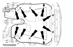
Remove the subframe rear retaining bolt and the subframe bracket retaining bolts on both sides. | | | -
Remove the subframe front retaining bolt on both sides. | | | -
CAUTION:To prevent damage to the lower arm hydro-bushing, make sure the subframe is lowered uniformly. | | | -
Remove the fender splash shield on both sides. | | | -
Using the special tool, detach the steering gear from the subframe. - Using cable ties, support the steering gear.
| | | -
CAUTION:Protect the ball joint seal using a soft cloth to prevent damage. Detach the lower arm ball joint from the wheel knuckle on both sides. | | | -
NOTE:If installing a new crossmember, remove the stabilizer bar. Remove the stabilizer bar (two bolts each side). | | | -
NOTE:If installing a new crossmember, remove the lower arms. Remove the lower arms (two bolts each side). | Installation All vehicles | | -
NOTE:If installing a new crossmember, install the lower arms. NOTE:Use new bolts and nuts. Install the lower arms. - Install the lower arm front retaining bolt in two stages.
- Install the lower arm rear retaining bolt in two stages.
| | | -
NOTE:If installing a new crossmember, install the stabilizer bar. Install the stabilizer bar (two bolts each side). | | | -
Using the transmission jack, position the subframe and lift it towards the body until the distance of the subframe to body is approximately 150 mm. | | | -
CAUTION:Make sure the heat shield is installed to prevent damage to the ball joint. Attach the lower arm ball joint to the wheel knuckle on both sides. | | | -
Using the special tool, attach the steering gear to the subframe. | | | -
Install the fender splash shield on both sides. | | | -
Using the special tool and a suitable washer, align the subframe. - Insert the washer, with inside diameter 22 mm, outside diameter 44 mm and height 5 mm, into the subframe above the lower alignment hole.
- Insert the alignment pin through the subframe alignment holes and the washer.
- Slide the locking plates on top of the washer and into the groove of the tool and tighten the alignment pin sleeve.
| | | -
CAUTION:While tightening the subframe retaining bolts, make sure the subframe does not move. Install the subframe rear retaining bolt and the subframe bracket retaining bolts on both sides. | | | -
CAUTION:While tightening the subframe retaining bolts, make sure the subframe does not move. Install the subframe front retaining bolt on both sides. | | | -
Remove the special tool and the washer. | Vehicles with electric booster heater | | -
Attach the electric booster heater to the subframe. | All vehicles | | -
NOTE:The lower arm pinch bolt must be installed from the rear. Install the lower arm ball joint to wheel knuckle pinch bolt and nut on both sides | | | -
Install the engine support insulator. | Vehicles with high intensity discharge headlamps | | -
Attach the headlamp leveling sensor wiring harness to the subframe. | | | -
Connect the headlamp leveling sensor electrical connector. | Vehicles with 1.8L, 2.0L or diesel engine | | -
Install the exhaust flexible pipe.
For additional information, refer to: Exhaust Flexible Pipe (309-00 Exhaust System, Removal and Installation).
| Vehicles with 2.5L engine | | -
Install the dual converter Y-pipe.
For additional information, refer to: Dual Catalytic Converter Y-Pipe (309-00 Exhaust System, Removal and Installation).
| Vehicles with 3.0L engine | | -
Install the exhaust flexible pipes.
For additional information, refer to: Exhaust Flexible Pipe (309-00 Exhaust System, Removal and Installation).
| All except vehicles with diesel engine | | -
Attach the catalyst monitor sensor wiring harness to the subframe. | | | -
Connect the catalyst monitor sensor electrical connector. | Vehicles with direct fuel injection | | -
Connect the heated oxygen sensor (HO2S) electrical connectors. | All vehicles | | -
Attach the radiator cooling fan wiring harness to the subframe. | | | -
Install the stabilizer bar connecting link to the suspension strut on both sides. | | | -
Install the radiator support bracket on both sides. - Install the radiator support bracket.
- Install the hose bracket (if equipped).
| | | -
Install the radiator splash shield. | | | -
Install the engine undershield (if equipped). | | | -
Install the front wheels and tires.
For additional information, refer to: Wheel and Tire (204-04 Wheels and Tires, Removal and Installation).
| | | -
Remove the cable ties, supporting the radiator. | | | -
Check the toe setting and adjust as necessary.
For additional information, refer to: Rear Toe Adjustment (204-00 Suspension System - General Information, General Procedures).
| |