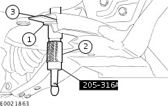
| Removal and Installation Special Tool(s) | | 205-316A Alignment Pins, Subframe | | | 211-020 Separator, Ball Joint | General Equipment Removal NOTE:Removal steps in this procedure may contain installation details. | | -
CAUTION:Make sure that the steering wheel lock is engaged. NOTE:Make sure that the road wheels are in the straight ahead position. | | | -
-
WARNING:Make sure the new steering column flexible coupling bolt is installed. Torque: 30 Nm | | | -
Remove the wheel and tire on both sides. | | | -
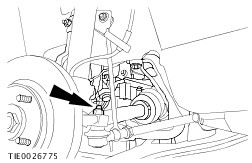
CAUTION:Make sure that the ball joint ball does not rotate. Loosen the tie-rod end nut, on both sides. | | | -
CAUTION:Use suitable packing material to prevent damage to the component. CAUTION:Make sure that the ball joint ball does not rotate. On both sides. Torque: 80 Nm | | | -
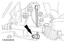
CAUTION:Make sure that the ball joint ball does not rotate. On both sides. Torque: 60 Nm | | | -
CAUTION:Make sure that the exhaust flexible pipe is not forcibly bent. | | | -
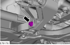
WARNING:Be prepared to collect escaping fluids. CAUTION:Make sure that all openings are sealed. Torque: 20 Nm | | | -
-
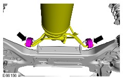
Torque: Stage 1: 150 Nm Stage 2: 90° | | | -
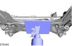
WARNING:This step requires the aid of another technician. Lower the front subframe and remove the steering gear on the driver side. Torque: Stage 1: 150 Nm Stage 2: 90° | Installation | | -
To install, reverse the removal procedure. | | | -
-
Insert the washer, with inside diameter 22mm, outside diameter 44mm and height 5mm, into the front frame above the alignment hole. -
Insert the alignment pin through the front subframe alignment holes and the washer. -
Slide the locking plates on top of the washer and into the groove of the special tool and tighten the alignment pin. | | | -
Fill the power steering system. | | | -
Bleed the power steering system. | | | -
Check the toe setting and adjust as necessary. | | |