| Diagnosis and Testing Principles of Operation The horn system consists of a relay, a steering wheel switch and either one or two horns. The horn(s) receives voltage from the switched side of the relay, and the relay switch is controlled on its ground side by the steering wheel switch. The horn relay, is located in the Battery junction box (BJB) and is supplied with a permanent voltage from the battery. The steering wheel horn switch shares the steering wheel clockspring circuit with the air-bag circuit. Each of these systems work completely independent of each other. Inspection and Verification - Verify the customer concern.
- Visually inspect for obvious signs of mechanical or electrical damage.
Visual Inspection Chart | Electrical | - Fuse(s)
- Wiring harness
- Electrical connector(s)
- Horn switch
- Horn
- Clockspring
- Horn relay
- BJB
| - If an obvious cause for an observed or reported concern is found, correct the cause (if possible) before proceeding to the next step.
- Retrieve the Diagnostic Trouble Code (DTC)s and refer to the DTC Index Chart.
Diagnostic Trouble Code (DTC) Index Chart | DTC | Description/Condition | Possible Source | Action | | 9C5512 | Horn relay- circuit short to battery | BJB | REFER to WDS. | | 9C5514 | Horn relay - circuit short to ground or open | BJB | REFER to WDS. | - If the cause is still evident, refer to the Symptom Chart.
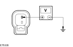
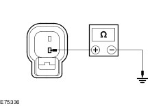
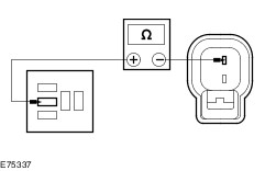
Symptom Chart | Symptom | Possible Sources | Action | | The horn is inoperative | * Circuit(s). * Horn. * Horn relay. * Clockspring. * Horn switch. * BJB | * | | The horn is always on | * Horn relay. * BJB * Horn switch. * Circuit(s). * Clockspring. | * REFER to WDS. | Pinpoint Tests | PINPOINT TEST A : THE HORN IS INOPERATIVE | | TEST CONDITIONS | DETAILS/RESULTS/ACTIONS | | A1: CHECK POWER TO THE HORN | | | 1 Disconnect Horn C1RH02. | | | 2 Measure the voltage between the horn C1RH02 pin 2, circuit GBB31B (BU/OG), harness side and ground while pressing the horn switch. | | | Is the voltage greater than 10 volts? Yes No | | A2: CHECK GROUND TO THE HORN | | | 1 Measure the resistance between the horn C1RH02 pin 1, circuit GD312G (BK/VT), harness side and ground. | | | Is the resistance less than 5 ohms? Yes INSTALL a new horn. TEST the system for normal operation. No REPAIR circuit GD312G (BK/VT). TEST the system for normal operation. | | A3: CHECK HORN POWER SUPPLY FOR OPEN | | | 1 Disconnect Horn Relay R9. | | | 2 Measure the resistance between the horn relay R9 pin 5, circuit CBB31B 9BU/OG) harness side and ground; and horn C1RH02 pin 2, circuit GBB31B (BU/OG), harness side and ground. | | | Is the resistance less than 5 ohms? Yes INSTALL a new horn relay R9. TEST the system for normal operation. If the concern persists, INSTALL a new horn. TEST the system for normal operation. No INSTALL a new BJB. TEST the system for normal operation. | |