| Diagnosis and Testing Principle of Operation For a detailed description of the parking aid system,
REFER to: Parking Aid (413-13, Description and Operation).
Inspection and Verification CAUTION:Diagnosis by substitution from a donor vehicle is NOT acceptable. Substitution of control modules does not guarantee confirmation of a fault, and may also cause additional faults in the vehicle being tested and/or the donor vehicle. - Verify the customer concern.
- Visually inspect for obvious signs of electrical damage.
NOTE:Particular attention should be paid to the following items where Diagnostic Trouble Codes (DTCs) may not be logged: - Check for contamination (e.g. foreign matter, grime, frosting, ice) around the parking aid sensors, if so clean as necessary.
- Check for the correct installation and alignment of the sensors to the bumper cover.
- Spurious detection of the ground may occur during front system operation on an up-slope.
Visual Inspection | Electrical | - Fuse(s)
- Relay(s)
- Wiring Harness
- Electrical connector(s)
- Front parking aid sensor(s) and retainers
- Rear parking aid sensor(s) and retainers
- Front parking aid speaker
- Rear parking aid speaker
- Parking aid switch and LED
- Reversing lamp switch
- Parking aid module
| - If an obvious cause for an observed or reported concern is found, correct the cause (if possible) before proceeding to the next step.
- If the cause is not visually evident, check for DTCs and refer to the DTC Index Chart.
DTC Index Chart NOTE:Generic scan tools may not read the DTCs listed, or may read only five digit codes. Match the five digits from the scan tool to the first five digits of the seven digit code listed to identify the concern (the last two digits give additional information read by the manufacturer approved diagnostic system). NOTE:When carrying out voltage or resistance tests, always use a digital multimeter (DMM) accurate to three decimal places, and with an up-to-date calibration certificate. When testing resistance always take the resistance of the DMM leads into account. NOTE:Check and rectify basic concerns before beginning diagnostic routines involving pinpoint tests. NOTE:Inspect electrical connectors for signs of water ingress, and pins for damage and/or corrosion. NOTE:If DTCs are recorded and, after carrying out the pinpoint tests, a fault is not present, an intermittent concern may be the cause. Always check for loose electrical connectors and corroded pins. | DTC | Description | Possible Cause | Action | | B1B3601 | Front outer right sensor | - Front outer right parking aid sensor signal circuit - short to ground, open circuit
- Front outer right parking aid sensor power supply circuit - open circuit
| Refer to the WDS to access pinpoint tests for this DTC. | | B1B3612 | Front outer right sensor | - Front outer right parking aid sensor signal circuit - short to power
| GO to Pinpoint Test A. | | B1B3696 | Front outer right sensor | - Front outer right parking aid sensor ground circuit open circuit
- Front outer right parking aid sensor internal failure
| GO to Pinpoint Test B. | | B1B3801 | Front inner right sensor | - Front inner right parking aid sensor signal circuit short to ground or open circuit
- Front inner right parking aid sensor power supply circuit open circuit
| Refer to the WDS to access pinpoint tests for this DTC. | | B1B3812 | Front inner right sensor | - Front inner right parking aid sensor signal circuit - short to power
| GO to Pinpoint Test C. | | B1B3896 | Front inner right sensor | - Front inner right parking aid sensor ground circuit - open circuit
- Front inner right parking aid sensor internal failure
| GO to Pinpoint Test D. | | B1B4001 | Front outer left sensor | - Front outer left parking aid sensor signal circuit - short to ground, open circuit
- Front outer left parking aid sensor power supply circuit - open circuit
| Refer to the WDS to access pinpoint tests for this DTC. | | B1B4012 | Front outer left sensor | - Front outer left parking aid sensor signal circuit - short to power
| GO to Pinpoint Test E. | | B1B4096 | Front outer left sensor | - Front outer left parking aid sensor ground circuit - open circuit
- Front outer left parking aid sensor internal failure
| GO to Pinpoint Test F. | | B1B4201 | Front inner left sensor | - Front inner left parking aid sensor signal circuit - short to ground, open circuit
- Front inner left parking aid sensor power supply circuit - open circuit
| Refer to the WDS to access pinpoint tests for this DTC. | | B1B4212 | Front inner left sensor | - Front inner left parking aid sensor signal circuit - short to power
| GO to Pinpoint Test G. | | B1B4296 | Front inner left sensor | - Front inner left parking aid sensor ground circuit - open circuit
- Front inner left parking aid sensor internal failure
| GO to Pinpoint Test H. | | B1B4401 | Rear outer right sensor | - Rear outer right parking aid sensor signal circuit - short to ground, open circuit
- Rear outer right parking aid sensor power supply circuit - open circuit
| Refer to the WDS to access pinpoint tests for this DTC. | | B1B4412 | Rear outer right sensor | - Rear outer right parking aid sensor signal circuit - short to power
| GO to Pinpoint Test I. | | B1B4496 | Rear outer right sensor | - Rear outer right parking aid sensor ground circuit - open circuit
- Rear outer right parking aid sensor internal failure
| GO to Pinpoint Test J. | | B1B4601 | Rear inner right sensor | - Rear inner right parking aid sensor signal circuit - short to ground, open circuit
- Rear inner right parking aid sensor power supply circuit - open circuit
| Refer to the WDS to access pinpoint tests for this DTC. | | B1B4612 | Rear inner right sensor | - Rear inner right parking aid sensor signal circuit - short to power
| GO to Pinpoint Test K. | | B1B4696 | Rear inner right sensor | - Rear inner right parking aid sensor ground circuit - open circuit
- Rear inner right parking aid sensor internal failure
| GO to Pinpoint Test L. | | B1B4801 | Rear outer left sensor | - Rear outer left parking aid sensor signal circuit - short to ground, open circuit
- Rear outer left parking aid sensor power supply circuit - open circuit
| Refer to the WDS to access pinpoint tests for this DTC. | | B1B4812 | Rear outer left sensor | - Rear outer left parking aid sensor signal circuit - short to power
| GO to Pinpoint Test M. | | B1B4896 | Rear outer left sensor | - Rear outer left parking aid sensor ground circuit - open circuit
- Rear outer left parking aid sensor internal failure
| GO to Pinpoint Test N. | | B1B5001 | Rear inner left sensor | - Rear inner left parking aid sensor signal circuit - short to ground, open circuit
- Rear inner left sensor power supply circuit - open circuit
| Refer to the WDS to access pinpoint tests for this DTC. | | B1B5012 | Rear inner left sensor | - Rear inner left parking aid sensor signal circuit - short to power
| GO to Pinpoint Test O. | | B1B5096 | Rear inner left sensor | - Rear inner left parking aid sensor ground circuit - open circuit
- Rear inner left parking aid sensor internal failure
| GO to Pinpoint Test P. | | B1B5201 | Rear parking aid speaker | - Rear parking aid speaker - internal fault
- Rear parking aid speaker circuit short to ground or open circuit
| GO to Pinpoint Test Q. | | B1B5212 | Rear parking aid speaker | - Rear parking aid speaker - short to power (detected if driven only)
| GO to Pinpoint Test R. | | B1B5301 | Front parking aid speaker | - Front parking aid speaker - internal fault
- Front parking aid speaker circuit short to ground or open circuit
| GO to Pinpoint Test S. | | B1B5312 | Front parking aid speaker | - Front parking aid speaker - short to power (detected if driven only)
| GO to Pinpoint Test T. | | B1B5411 | Parking aid status LED | - Parking aid status LED - short to ground (detected if driven only)
| GO to Pinpoint Test U. | | B1B5412 | Parking aid status LED | - Parking aid status LED - short to power (detected if not driven only)
| GO to Pinpoint Test V. | | B1B5711 | Front parking aid sensors power supply circuit | - Front parking aid sensors power supply circuit - short to ground
| GO to Pinpoint Test W. | | B1B5811 | Rear parking aid sensors power supply circuit | - Rear parking aid sensors power supply circuit - short to ground
| GO to Pinpoint Test X. | | B1C3073 | Parking aid switch | - Parking aid switch stuck closed
- Parking aid switch circuit - short circuit
| Refer to the WDS to access pinpoint tests for this DTC. | | U001000 | Medium speed CAN bus | | REFER to: Communications Network (418-00, Diagnosis and Testing). | | U007300 | Parking aid module bus "A" Off | - Parking aid module communication bus "A" Off
| REFER to: Communications Network (418-00, Diagnosis and Testing). | | U014000 | Communication lost with the CJB | - Logged when subscribed CAN message missing from the CJB
| REFER to: Communications Network (418-00, Diagnosis and Testing). | | U025200 | Communication lost with the lighting control module - rear "B" | CAN message missing from trailer module | REFER to: Communications Network (418-00, Diagnosis and Testing). | | U030000 | Internal parking aid module software incompatibility | - CJB car configuration data is not compatible with the parking aid module
| Re-configure the CJB using the WDS. Clear the DTC(s) and re-test. If DTC(s) still logged, install a new parking aid module.
REFER to: Parking Aid Module (413-13, Removal and Installation).
| | U042200 | Invalid data received from the CJB | - Logged when subscribed CAN message invalid from the CJB
| Check the CJB for DTC(s) and refer to the DTC Index.
REFER to: Communications Network (418-00, Diagnosis and Testing).
| | U048400 | Invalid data received from the lighting control module - rear "B" | CAN message invalid from trailer module | REFER to: Communications Network (418-00, Diagnosis and Testing). | | U210000 | Initial configuration not complete | - No configuration has been previously set
| Re-configure the CJB using the WDS. Clear the DTC(s) and re-test. If DTC(s) still logged, check the CAN network.
REFER to: Communications Network (418-00, Diagnosis and Testing).
| | U210100 | Parking aid module configuration incompatible | - Data sent from the CJB is invalid
| Re-configure the CJB using the WDS. Clear the DTC(s) and re-test. If DTC(s) still logged, check the CAN network.
REFER to: Communications Network (418-00, Diagnosis and Testing).
| | U300049 | Parking aid module | - Internal parking aid module failure
| Install a new parking aid control module.
REFER to: Parking Aid Module (413-13, Removal and Installation).
| | U300316 | Battery voltage | - Circuit voltage below threshold
| REFER to: Charging System (414-00, Diagnosis and Testing). | | U300317 | Battery voltage | - Circuit voltage above threshold
| REFER to: Charging System (414-00, Diagnosis and Testing). | | U300362 | Battery voltage | - Mis-match in battery voltage, of 2 volts or lower, between the parking aid module and the CJB
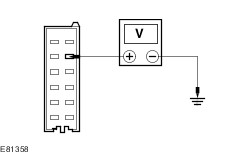
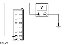
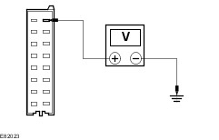
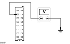
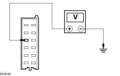
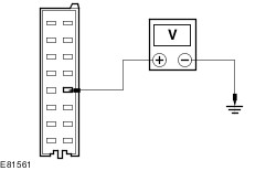
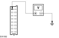
| GO to Pinpoint Test Y. | Pinpoint Tests | PINPOINT TEST A : DTC B1B3612 - FRONT OUTER RIGHT PARKING AID SENSOR SIGNAL - SHORT TO POWER | | TEST CONDITIONS | DETAILS/RESULTS/ACTIONS | | A1: CHECK CIRCUIT VMP13 (BU/OG) FOR SHORT TO POWER | | | 1 Disconnect Front outer right parking aid sensor C1MP13. | | | 2 Disconnect Parking aid module C4MP01B. | | | 3 Ignition switch in position II. | | | 4 Measure the voltage between the parking aid module C4MP01B pin 8, circuit VMP13A (BU/OG), harness side and ground. | | | Is a voltage present? Yes REPAIR the circuit. TEST the system for normal operation. No INSTALL a new front outer right parking aid sensor.
REFER to: Front Parking Aid Sensor (413-13, Removal and Installation).
TEST the system for normal operation. If the concern persists, INSTALL a new parking aid module.
REFER to: Parking Aid Module (413-13, Removal and Installation).
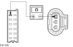
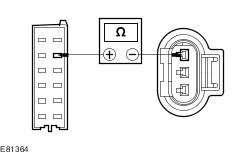
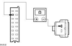
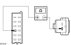
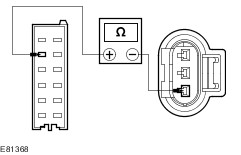
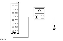
TEST the system for normal operation. | | PINPOINT TEST B : DTC B1B3696 - FRONT OUTER RIGHT PARKING AID SENSOR - GROUND CIRCUIT OPEN OR PARKING AID SENSOR INTERNAL FAILURE | | TEST CONDITIONS | DETAILS/RESULTS/ACTIONS | | B1: CHECK CIRCUIT RMP06 (YE/OG) FOR OPEN | | | 1 Disconnect Front outer right parking aid sensor C1MP13. | | | 2 Disconnect Parking aid module C4MP01B. | | | 3 Measure the resistance between the parking aid module C4MP01B pin 1, circuit RMP06A (YE/OG), harness side and the front outer right parking aid sensor C1MP13 pin 3, circuit RMP06C (YE/OG), harness side. | | | Is the resistance less than 1 Ohm? Yes INSTALL a new front outer right parking aid sensor.
REFER to: Front Parking Aid Sensor (413-13, Removal and Installation).
TEST the system for normal operation. If the concern persists, INSTALL a new parking aid module.
REFER to: Parking Aid Module (413-13, Removal and Installation).
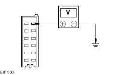
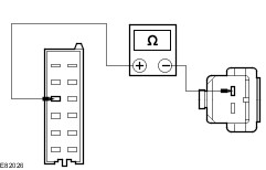
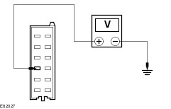
TEST the system for normal operation. No REPAIR the circuit. TEST the system for normal operation. | | PINPOINT TEST C : DTC B1B3812 - FRONT INNER RIGHT PARKING AID SENSOR SIGNAL - SHORT TO POWER | | TEST CONDITIONS | DETAILS/RESULTS/ACTIONS | | C1: CHECK CIRCUIT VMP12 (BU/GY) FOR SHORT TO POWER | | | 1 Disconnect Front inner right parking aid sensor C1MP12. | | | 2 Disconnect Parking aid module C4MP01B. | | | 3 Ignition switch in position II. | | | 4 Measure the voltage between the parking aid module C4MP01B pin 7, circuit VMP12A (BU/GY), harness side and ground. | | | Is a voltage present? Yes REPAIR the circuit. TEST the system for normal operation. No INSTALL a new front inner right parking aid sensor.
REFER to: Front Parking Aid Sensor (413-13, Removal and Installation).
TEST the system for normal operation. If the concern persists, INSTALL a new parking aid module.
REFER to: Parking Aid Module (413-13, Removal and Installation).
TEST the system for normal operation. | | PINPOINT TEST D : DTC B1B3896 - FRONT INNER RIGHT PARKING AID SENSOR - GROUND CIRCUIT OPEN OR PARKING AID SENSOR INTERNAL FAILURE | | TEST CONDITIONS | DETAILS/RESULTS/ACTIONS | | D1: CHECK CIRCUIT RMP06 (YE/OG) FOR OPEN | | | 1 Disconnect Front inner right parking aid sensor C1MP12. | | | 2 Disconnect Parking aid module C4MP01B. | | | 3 Measure the resistance between the parking aid module C4MP01B pin 1, circuit RMP06A (YE/OG), harness side and the front inner right parking aid sensor C1MP12 pin 3, circuit RMP06E (YE/OG), harness side. | | | Is the resistance less than 1 Ohm? Yes INSTALL a new front inner right parking aid sensor.
REFER to: Front Parking Aid Sensor (413-13, Removal and Installation).
TEST the system for normal operation. If the concern persists, INSTALL a new parking aid module.
REFER to: Parking Aid Module (413-13, Removal and Installation).
TEST the system for normal operation. No REPAIR the circuit. TEST the system for normal operation. | | PINPOINT TEST E : DTC B1B4012 - FRONT OUTER LEFT PARKING AID SENSOR SIGNAL - SHORT TO POWER | | TEST CONDITIONS | DETAILS/RESULTS/ACTIONS | | E1: CHECK CIRCUIT VMP11 (BU/GN) FOR SHORT TO POWER | | | 1 Disconnect Front outer left parking aid sensor C1MP11. | | | 2 Disconnect Parking aid module C4MP01B. | | | 3 Ignition switch in position II. | | | 4 Measure the voltage between the parking aid module C4MP01B pin 7, circuit VMP11A (BU/GN), harness side and ground. | | | Is a voltage present? Yes REPAIR the circuit. TEST the system for normal operation. No INSTALL a new front outer left parking aid sensor.
REFER to: Front Parking Aid Sensor (413-13, Removal and Installation).
TEST the system for normal operation. If the concern persists, INSTALL a new parking aid module.
REFER to: Parking Aid Module (413-13, Removal and Installation).
TEST the system for normal operation. | | PINPOINT TEST F : DTC B1B4096 - FRONT OUTER LEFT PARKING AID SENSOR - GROUND CIRCUIT OPEN OR PARKING AID SENSOR INTERNAL FAILURE | | TEST CONDITIONS | DETAILS/RESULTS/ACTIONS | | F1: CHECK CIRCUIT RMP06 (YE/OG) FOR OPEN | | | 1 Disconnect Front outer left parking aid sensor C1MP11. | | | 2 Disconnect Parking aid module C4MP01B. | | | 3 Measure the resistance between the parking aid module C4MP01B pin 1, circuit RMP06A (YE/OG), harness side and the front outer left parking aid sensor C1MP11 pin 3, circuit RMP06F (YE/OG), harness side. | | | Is the resistance less than 1 Ohm? Yes INSTALL a new front outer left parking aid sensor.
REFER to: Front Parking Aid Sensor (413-13, Removal and Installation).
TEST the system for normal operation. If the concern persists, INSTALL a new parking aid module.
REFER to: Parking Aid Module (413-13, Removal and Installation).
TEST the system for normal operation. No REPAIR the circuit. TEST the system for normal operation. | | PINPOINT TEST G : DTC B1B4212 - FRONT INNER LEFT PARKING AID SENSOR SIGNAL - SHORT TO POWER | | TEST CONDITIONS | DETAILS/RESULTS/ACTIONS | | G1: CHECK CIRCUIT VMP10 (WH/BU) FOR SHORT TO POWER | | | 1 Disconnect Front inner left parking aid sensor C1MP10. | | | 2 Disconnect Parking aid module C4MP01B. | | | 3 Ignition switch in position II. | | | 4 Measure the voltage between the parking aid module C4MP01B pin 6, circuit VMP10A (WH/BU), harness side and ground. | | | Is a voltage present? Yes REPAIR the circuit. TEST the system for normal operation. No INSTALL a new front inner left parking aid sensor.
REFER to: Front Parking Aid Sensor (413-13, Removal and Installation).
TEST the system for normal operation. If the concern persists, INSTALL a new parking aid module.
REFER to: Parking Aid Module (413-13, Removal and Installation).
TEST the system for normal operation. | | PINPOINT TEST H : DTC B1B4296 - FRONT INNER LEFT PARKING AID SENSOR - GROUND CIRCUIT OPEN OR PARKING AID SENSOR INTERNAL FAILURE | | TEST CONDITIONS | DETAILS/RESULTS/ACTIONS | | H1: CHECK CIRCUIT RMP06 (YE/OG) FOR OPEN | | | 1 Disconnect Front inner left parking aid sensor C1MP10. | | | 2 Disconnect Parking aid module C4MP01B. | | | 3 Measure the resistance between the parking aid module C4MP01B pin 1, circuit RMP06A (YE/OG), harness side and the front inner left parking aid sensor C1MP10 pin 3, circuit RMP06G (YE/OG), harness side. | | | Is the resistance less than 1 Ohm? Yes INSTALL a new front inner left parking aid sensor.
REFER to: Front Parking Aid Sensor (413-13, Removal and Installation).
TEST the system for normal operation. If the concern persists, INSTALL a new parking aid module.
REFER to: Parking Aid Module (413-13, Removal and Installation).
TEST the system for normal operation. No REPAIR the circuit. TEST the system for normal operation. | | PINPOINT TEST I : DTC B1B4412 - REAR OUTER RIGHT PARKING AID SENSOR SIGNAL - SHORT TO POWER | | TEST CONDITIONS | DETAILS/RESULTS/ACTIONS | | I1: CHECK CIRCUIT VMP17 (YE/OG) FOR SHORT TO POWER | | | 1 Disconnect Rear outer right parking aid sensor C4MP17. | | | 2 Disconnect Parking aid module C4MP01C. | | | 3 Ignition switch in position II. | | | 4 Measure the voltage between the parking aid module C4MP01C pin 4, circuit VMP17A (YE/OG), harness side and ground. | | | Is a voltage present? Yes REPAIR the circuit. TEST the system for normal operation. No INSTALL a new rear outer right parking aid sensor.
REFER to: Rear Parking Aid Sensor (413-13, Removal and Installation).
TEST the system for normal operation. If the concern persists, INSTALL a new parking aid module.
REFER to: Parking Aid Module (413-13, Removal and Installation).
TEST the system for normal operation. | | PINPOINT TEST J : DTC B1B4496 - REAR OUTER RIGHT PARKING AID SENSOR - GROUND CIRCUIT OPEN OR PARKING AID SENSOR INTERNAL FAILURE | | TEST CONDITIONS | DETAILS/RESULTS/ACTIONS | | J1: CHECK CIRCUIT RMP07 (GN/WH) FOR OPEN | | | 1 Disconnect Rear outer right parking aid sensor C4MP17. | | | 2 Disconnect Parking aid module C4MP01C. | | | 3 Measure the resistance between the parking aid module C4MP01C pin 8, circuit RMP07A (GN/WH), harness side and the rear outer right parking aid sensor C4MP17 pin 3, circuit RMP07E (GN/WH), harness side. | | | Is the resistance less than 1 Ohm? Yes INSTALL a new rear outer right parking aid sensor.
REFER to: Rear Parking Aid Sensor (413-13, Removal and Installation).
TEST the system for normal operation. If the concern persists, INSTALL a new parking aid module.
REFER to: Parking Aid Module (413-13, Removal and Installation).
TEST the system for normal operation. No REPAIR the circuit. TEST the system for normal operation. | | PINPOINT TEST K : DTC B1B4612 - REAR INNER RIGHT PARKING AID SENSOR SIGNAL - SHORT TO POWER | | TEST CONDITIONS | DETAILS/RESULTS/ACTIONS | | K1: CHECK CIRCUIT VMP16 (YE/GY) FOR SHORT TO POWER | | | 1 Disconnect Rear inner right parking aid sensor C4MP16. | | | 2 Disconnect Parking aid module C4MP01C. | | | 3 Ignition switch in position II. | | | 4 Measure the voltage between the parking aid module C4MP01C pin 2, circuit VMP16A (YE/GY), harness side and ground. | | | Is a voltage present? Yes REPAIR the circuit. TEST the system for normal operation. No INSTALL a new rear inner right parking aid sensor.
REFER to: Rear Parking Aid Sensor (413-13, Removal and Installation).
TEST the system for normal operation. If the concern persists, INSTALL a new parking aid module.
REFER to: Parking Aid Module (413-13, Removal and Installation).
TEST the system for normal operation. | | PINPOINT TEST L : DTC B1B4696 - REAR INNER RIGHT PARKING AID SENSOR - GROUND CIRCUIT OPEN OR PARKING AID SENSOR INTERNAL FAILURE | | TEST CONDITIONS | DETAILS/RESULTS/ACTIONS | | L1: CHECK CIRCUIT RMP07 (GN/WH) FOR OPEN | | | 1 Disconnect Rear inner right parking aid sensor C4MP16. | | | 2 Disconnect Parking aid module C4MP01C. | | | 3 Measure the resistance between the parking aid module C4MP01C pin 8, circuit RMP07A (GN/WH), harness side and the rear inner right parking aid sensor C4MP16 pin 3, circuit RMP07D (GN/WH), harness side. | | | Is the resistance less than 1 Ohm? Yes INSTALL a new rear inner right parking aid sensor.
REFER to: Rear Parking Aid Sensor (413-13, Removal and Installation).
TEST the system for normal operation. If the concern persists, INSTALL a new parking aid module.
REFER to: Parking Aid Module (413-13, Removal and Installation).
TEST the system for normal operation. No REPAIR the circuit. TEST the system for normal operation. | | PINPOINT TEST M : DTC B1B4812 - REAR OUTER LEFT PARKING AID SENSOR SIGNAL - SHORT TO POWER | | TEST CONDITIONS | DETAILS/RESULTS/ACTIONS | | M1: CHECK CIRCUIT VMP15 (YE/GN) FOR SHORT TO POWER | | | 1 Disconnect Rear outer left parking aid sensor C4MP15. | | | 2 Disconnect Parking aid module C4MP01C. | | | 3 Ignition switch in position II. | | | 4 Measure the voltage between the parking aid module C4MP01C pin 5, circuit VMP15A (YE/GN), harness side and ground. | | | Is a voltage present? Yes REPAIR the circuit. TEST the system for normal operation. No INSTALL a new rear outer left parking aid sensor.
REFER to: Rear Parking Aid Sensor (413-13, Removal and Installation).
TEST the system for normal operation. If the concern persists, INSTALL a new parking aid module.
REFER to: Parking Aid Module (413-13, Removal and Installation).
TEST the system for normal operation. | | PINPOINT TEST N : DTC B1B4896 - REAR OUTER LEFT PARKING AID SENSOR - GROUND CIRCUIT OPEN OR PARKING AID SENSOR INTERNAL FAILURE | | TEST CONDITIONS | DETAILS/RESULTS/ACTIONS | | N1: CHECK CIRCUIT RMP07 (GN/WH) FOR OPEN | | | 1 Disconnect Rear outer left parking aid sensor C4MP15. | | | 2 Disconnect Parking aid module C4MP01C. | | | 3 Measure the resistance between the parking aid module C4MP01C pin 8, circuit RMP07A (GN/WH), harness side and the rear outer left parking aid sensor C4MP15 pin 3, circuit RMP07B (GN/WH), harness side. | | | Is the resistance less than 1 Ohm? Yes INSTALL a new rear outer left parking aid sensor.
REFER to: Rear Parking Aid Sensor (413-13, Removal and Installation).
TEST the system for normal operation. If the concern persists, INSTALL a new parking aid module.
REFER to: Parking Aid Module (413-13, Removal and Installation).
TEST the system for normal operation. No REPAIR the circuit. TEST the system for normal operation. | | PINPOINT TEST O : DTC B1B5012 - REAR INNER LEFT PARKING AID SENSOR SIGNAL - SHORT TO POWER | | TEST CONDITIONS | DETAILS/RESULTS/ACTIONS | | O1: CHECK CIRCUIT VMP14 (WH/OG) FOR SHORT TO POWER | | | 1 Disconnect Rear inner left parking aid sensor C4MP14. | | | 2 Disconnect Parking aid module C4MP01C. | | | 3 Ignition switch in position II. | | | 4 Measure the voltage between the parking aid module C4MP01C pin 3, circuit VMP14A (WH/OG), harness side and ground. | | | Is a voltage present? Yes REPAIR the circuit. TEST the system for normal operation. No INSTALL a new rear inner left parking aid sensor.
REFER to: Rear Parking Aid Sensor (413-13, Removal and Installation).
TEST the system for normal operation. If the concern persists, INSTALL a new parking aid module.
REFER to: Parking Aid Module (413-13, Removal and Installation).
TEST the system for normal operation. | | PINPOINT TEST P : DTC B1B5096 - REAR INNER LEFT PARKING AID SENSOR - GROUND CIRCUIT OPEN OR PARKING AID SENSOR INTERNAL FAILURE | | TEST CONDITIONS | DETAILS/RESULTS/ACTIONS | | P1: CHECK CIRCUIT RMP07 (GN/WH) FOR OPEN | | | 1 Disconnect Rear inner left parking aid sensor C4MP14. | | | 2 Disconnect Parking aid module C4MP01C. | | | 3 Measure the resistance between the parking aid module C4MP01C pin 8, circuit RMP07A (GN/WH), harness side and the rear inner left parking aid sensor C4MP14 pin 3, circuit RMP07F (GN/WH), harness side. | | | Is the resistance less than 1 Ohm? Yes INSTALL a new rear inner left parking aid sensor.
REFER to: Rear Parking Aid Sensor (413-13, Removal and Installation).
TEST the system for normal operation. If the concern persists, INSTALL a new parking aid module.
REFER to: Parking Aid Module (413-13, Removal and Installation).
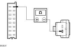
TEST the system for normal operation. No REPAIR the circuit. TEST the system for normal operation. | | PINPOINT TEST Q : DTC B1B5201 - REAR PARKING AID SPEAKER - INTERNAL FAULT, SHORT TO GROUND OR OPEN CIRCUIT | | TEST CONDITIONS | DETAILS/RESULTS/ACTIONS | | Q1: CHECK CIRCUIT CMP09A (BN/BU) FOR OPEN | | | 1 Disconnect Parking aid module C4MP01A. | | | 2 Disconnect Rear parking aid speaker C4MP09. | | | 3 Measure the resistance between the parking aid module C4MP01A pin 10, circuit CMP09A (BN/BU), harness side and the rear parking aid speaker C4MP09 pin 1, circuit CMP09A (BN/BU), harness side. | | | Is the resistance less than 1 Ohm? Yes No REPAIR the circuit. TEST the system for normal operation. | | Q2: CHECK CIRCUIT RMP09A (BU/GN) FOR OPEN | | | 1 Measure the resistance between the parking aid module C4MP01A pin 2, circuit RMP09A (BU/GN), harness side and the rear parking aid speaker C4MP09 pin 2, circuit RMP09A (BU/GN), harness side. | | | Is the resistance less than 1 Ohm? Yes INSTALL a new rear parking aid speaker. TEST the system for normal operation. If the concern persists, INSTALL a new parking aid module.
REFER to: Parking Aid Module (413-13, Removal and Installation).
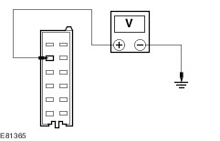
TEST the system for normal operation. No REPAIR the circuit. TEST the system for normal operation. | | PINPOINT TEST R : DTC B1B5212 - REAR PARKING AID SPEAKER - SHORT TO POWER | | TEST CONDITIONS | DETAILS/RESULTS/ACTIONS | | R1: CHECK CIRCUIT CMP09A (BN/BU) FOR SHORT TO POWER | | | 1 Disconnect Parking aid module C4MP01A. | | | 2 Disconnect Rear parking aid speaker C4MP09. | | | 3 Ignition switch in position II. | | | 4 Measure the voltage between the parking aid module C4MP01A pin 10, circuit CMP09A (BN/BU), harness side and ground. | | | Is a voltage present? Yes REPAIR the circuit. TEST the system for normal operation. No | | R2: CHECK CIRCUIT RMP09A (BU/GN) FOR SHORT TO POWER | | | 1 Measure the voltage between the parking aid module C4MP01A pin 2, circuit RMP09A (BU/GN), harness side and ground. | | | Is a voltage present? Yes REPAIR the circuit. TEST the system for normal operation. No INSTALL a new rear parking aid speaker. TEST the system for normal operation. If the concern persists, INSTALL a new parking aid module.
REFER to: Parking Aid Module (413-13, Removal and Installation).
TEST the system for normal operation. | | PINPOINT TEST S : DTC B1B5301 - FRONT PARKING AID SPEAKER - INTERNAL FAULT, SHORT TO GROUND OR OPEN CIRCUIT | | TEST CONDITIONS | DETAILS/RESULTS/ACTIONS | | S1: CHECK CIRCUIT CMP08 (GY/BN) FOR OPEN | | | 1 Disconnect Parking aid module C4MP01B. | | | 2 Disconnect Front parking aid speaker C2MP08. | | | 3 Measure the resistance between the parking aid module C4MP01B pin 4, circuit CMP08A (GY/BN), harness side and the front parking aid speaker C2MP08 pin 1, circuit CMP08B (GY/BN), harness side. | | | Is the resistance less than 1 Ohm? Yes No REPAIR the circuit. TEST the system for normal operation. | | S2: CHECK CIRCUIT RMP08 (VT/OG) FOR OPEN | | | 1 Measure the resistance between the parking aid module C4MP01B pin 3, circuit RMP08A (VT/OG), harness side and the front parking aid speaker C2MP08 pin 2, circuit RMP08B (VT/OG), harness side. | | | Is the resistance less than 1 Ohm? Yes INSTALL a new front parking aid speaker. TEST the system for normal operation. If the concern persists, INSTALL a new parking aid module.
REFER to: Parking Aid Module (413-13, Removal and Installation).
TEST the system for normal operation. No REPAIR the circuit. TEST the system for normal operation. | | PINPOINT TEST T : DTC B1B5312 - FRONT PARKING AID SPEAKER - SHORT TO POWER | | TEST CONDITIONS | DETAILS/RESULTS/ACTIONS | | T1: CHECK CIRCUIT CMP08 (GY/BN) FOR SHORT TO POWER | | | 1 Disconnect Parking aid module C4MP01B. | | | 2 Disconnect Front parking aid speaker C2MP08. | | | 3 Ignition switch in position II. | | | 4 Measure the voltage between the parking aid module C4MP01B pin 4, circuit CMP08B (GY/BN), harness side and ground. | | | Is a voltage present? Yes REPAIR the circuit. TEST the system for normal operation. No | | T2: CHECK CIRCUIT RMP08 (VT/OG) FOR SHORT TO POWER | | | 1 Measure the voltage between the parking aid module C4MP01B pin 3, circuit RMP08A (VT/OG), harness side and ground. | | | Is a voltage present? Yes REPAIR the circuit. TEST the system for normal operation. No INSTALL a new front parking aid speaker. TEST the system for normal operation. If the concern persists, INSTALL a new parking aid module.
REFER to: Parking Aid Module (413-13, Removal and Installation).
TEST the system for normal operation. | | PINPOINT TEST U : DTC B1B5411 - PARKING AID STATUS LED - SHORT TO GROUND | | TEST CONDITIONS | DETAILS/RESULTS/ACTIONS | | U1: CHECK CIRCUIT CMP02 (GN/BU) FOR OPEN | | | 1 Disconnect Parking aid module C4MP01A. | | | 2 Disconnect Parking aid switch C2CA1S. | | | 3 Measure the resistance between the parking aid module C4MP01A pin 13, circuit CMP02A (GN/BU), harness side and ground. | | | Is the resistance greater than 10,000 Ohms? Yes INSTALL a new parking aid switch. TEST the system for normal operation. If the concern persists, INSTALL a new parking aid module.
REFER to: Parking Aid Module (413-13, Removal and Installation).
TEST the system for normal operation. No REPAIR the circuit. TEST the system for normal operation. | | PINPOINT TEST V : B1B5412 - PARKING AID STATUS LED - SHORT TO POWER | | TEST CONDITIONS | DETAILS/RESULTS/ACTIONS | | V1: CHECK CIRCUIT CMP02 (GN/BU) FOR SHORT TO POWER | | | 1 Disconnect Parking aid module C4MP01A. | | | 2 Disconnect Parking aid switch C2CA1S. | | | 3 Ignition switch in position II. | | | 4 Measure the voltage between the parking aid module C4MP01A pin 13, circuit CMP02A (GN/BU), harness side and ground. | | | Is a voltage present? Yes REPAIR the circuit. TEST the system for normal operation. No INSTALL a new parking aid switch. TEST the system for normal operation. If the concern persists, INSTALL a new parking aid module.
REFER to: Parking Aid Module (413-13, Removal and Installation).
TEST the system for normal operation. | | PINPOINT TEST W : DTC B1B5711 - FRONT PARKING AID SENSORS - POWER SUPPLY CIRCUIT SHORT TO GROUND | | TEST CONDITIONS | DETAILS/RESULTS/ACTIONS | | W1: CHECK CIRCUIT LMP06 (VT/GY) FOR OPEN | | | 1 Disconnect Front outer right parking aid sensor C1MP13. | | | 2 Disconnect Front inner right parking aid sensor C1MP12. | | | 3 Disconnect Front outer left parking aid sensor C1MP11. | | | 4 Disconnect Front inner left parking aid sensor C1MP10. | | | 5 Disconnect Parking aid module C4MP01B. | | | 6 Measure the resistance between the parking aid module C4MP01B pin 2, circuit LMP06A (VT/GY), harness side and the following electrical connectors. - Front outer right parking aid sensor C1MP13 pin 1, circuit LMP06C (VT/GY), harness side.
- Front inner right parking aid sensor C1MP12 pin 1, circuit LMP06F (VT/GY), harness side.
- Front outer left parking aid sensor C1MP11 pin 1, circuit LMP06E (VT/GY), harness side.
- Front inner left parking aid sensor C1MP10 pin 1, circuit LMP06G (VT/GY), harness side.
| | | Are the resistances less than 1 Ohm? Yes REPAIR the circuit(s). TEST the system for normal operation. No INSTALL a new parking aid sensor(s) as required.
REFER to: Front Parking Aid Sensor (413-13, Removal and Installation).
TEST the system for normal operation. If the concern persists, INSTALL a new parking aid module.
REFER to: Parking Aid Module (413-13, Removal and Installation).
TEST the system for normal operation. | | PINPOINT TEST X : DTC B1B5811 - REAR PARKING AID SENSORS - POWER SUPPLY CIRCUIT SHORT TO GROUND | | TEST CONDITIONS | DETAILS/RESULTS/ACTIONS | | X1: CHECK CIRCUIT LMP07 (BU/WH) FOR OPEN | | | 1 Disconnect Rear outer right parking aid sensor C1MP17. | | | 2 Disconnect Rear inner right parking aid sensor C1MP16. | | | 3 Disconnect Rear outer left parking aid sensor C1MP15. | | | 4 Disconnect Rear inner left parking aid sensor C1MP14. | | | 5 Disconnect Parking aid module C4MP01C. | | | 6 Measure the resistance between the parking aid module C4MP01C pin 11, circuit LMP07A (BU/WH), harness side and the following electrical connectors. - Rear outer right parking aid sensor C1MP17 pin 1, circuit LMP07F (BU/WH), harness side.
- Rear inner right parking aid sensor C1MP16 pin 1, circuit LMP07E (BU/WH), harness side.
- Rear outer left parking aid sensor C1MP15 pin 1, circuit LMP07B (BU/WH), harness side.
- Rear inner left parking aid sensor C1MP14 pin 1, circuit LMP07D (BU/WH), harness side.
| | | Are the resistances less than 1 Ohm? Yes REPAIR the circuit(s). TEST the system for normal operation. No INSTALL a new parking aid sensor(s) as required.
REFER to: Rear Parking Aid Sensor (413-13, Removal and Installation).
TEST the system for normal operation. If the concern persists, INSTALL a new parking aid module.
REFER to: Parking Aid Module (413-13, Removal and Installation).
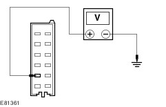
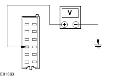
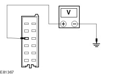
TEST the system for normal operation. | | PINPOINT TEST Y : DTC U300362 - MIS-MATCH IN BATTERY VOLTAGE BETWEEN THE PARKING AID MODULE AND THE CJB | | TEST CONDITIONS | DETAILS/RESULTS/ACTIONS | | Y1: CHECK CIRCUIT CBR01AWA (BU) FOR POWER | | | 1 Disconnect Parking aid module C4MP01A. | | | 2 Ignition switch in position II. | | | 3 Measure the voltage between the parking aid module C4MP01A pin 1, circuit CBR01AWA (BU), harness side and ground. | | | Is the voltage greater than 10 volts? Yes No REPAIR the circuit. TEST the system for normal operation. If the concern persists,
REFER to: Communications Network (418-00, Diagnosis and Testing).
| | Y2: CHECK CIRCUIT GD152 (BK/BU) FOR OPEN | | | 1 Ignition switch in position 0. | | | 2 Measure the resistance between the parking aid module C4MP01A pin 8, circuit GD152 (BK/BU), harness side and ground. | | | Is the resistance less than 1 Ohm? Yes INSTALL a new parking aid module.
REFER to: Parking Aid Module (413-13, Removal and Installation).
TEST the system for normal operation. No CLEAN and TIGHTEN the ground connection. TEST the system for normal operation. If the concern persists, REPAIR the circuit. TEST the system for normal operation. | |