| PINPOINT TEST A : TRAILER LAMPS INOPERATIVE, LAMPS ON VEHICLE OK |
| TEST CONDITIONS | DETAILS/RESULTS/ACTIONS |
| A1: DETERMINE THE CAUSE OF THE FAULT |
| | 1 Ignition switch in position II. |
| | 2 CHECK the trailer lamps after every step. |
| | 3 APPLY the brakes. |
| | 4 SWITCH ON the dipped beam. |
| | 5 SWITCH ON the rear fog lamps. |
| | 6 SWITCH ON the left-hand turn signal. |
| | 7 SWITCH ON the right-hand turn signal. |
| | 8 ENGAGE reverse gear. |
| | Are all trailer lamps inoperative? Yes No - Both trailer stoplamps inoperative: GO to A7. - Both trailer rear lamps inoperative: GO to A17. - Trailer rear fog lamp inoperative: GO to A11. - Both trailer turn signal lamps inoperative: RENEW trailer module. CHECK system operates correctly - Trailer backup lamp inoperative: GO to A14. - Stoplamps functioning and parking lamps permanently lit:
REFER to: Communications Network (418-00 Module Communications Network, Diagnosis and Testing).
|
| A2: CHECK GROUND CONNECTION OF TRAILER SOCKET FOR OPEN CIRCUIT |
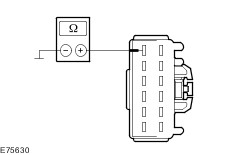
| | 1 Measure the resistance between the trailer socket, connector C4AT23-D, pin 3, circuit GD160A(B) (BR/WH) and ground. |
| | Is a resistance of less than 2 Ohms registered? Yes No LOCATE and RECTIFY the break in the circuit GD160A(B) (BR/WH) between the trailer socket and ground connection G4D151-A with the aid of the Wiring Diagrams. CHECK system operates correctly If necessary RENEW the trailer socket. CHECK system operates correctly |
| A3: CHECK FUSE FA11 (40 A) (RJB) |
| | 1 Ignition switch in position 0. |
| | 2 Disconnect Fuse FA11 (40 A) (RJB). |
| | 3 CHECK Fuse FA11 (40 A) (RJB). |
| | Is the fuse in order? Yes No RENEW fuse FA11 (40 A) (RJB) and CHECK the operation of the system. If the fuse blows again, LOCATE and RECTIFY the short using the Wiring Diagrams. CHECK system operates correctly |
| A4: CHECK THE VOLTAGE SUPPLY TO FUSE FA11 (40 A) (RJB) FOR OPEN CIRCUIT |
| | 1 Connect Fuse FA11 (40 A) (RJB). |
| | 2 Ignition switch in position II. |
| | 3 Measure the voltage between fuse FA11 (40 A) (RJB) and ground. |
| | Does meter display battery voltage? Yes No LOCATE and RECTIFY the break in the voltage supply of fuse FA11 (40 A) (RJB) with the aid of the Wiring Diagrams. CHECK system operates correctly |
| A5: CHECK VOLTAGE SUPPLY OF TRAILER MODULE FOR OPEN CIRCUIT |
| | 1 Ignition switch in position 0. |
| | 2 Disconnect Trailer module from connector C4AT23-B. |
| | 3 Ignition switch in position II. |
| | 4 Measure the voltage between the trailer module, connector C4AT23-B, pin 2, circuit SBR11A (BU/RD), wiring harness side and ground. |
| | Does the meter display battery voltage? Yes No LOCATE and RECTIFY break in circuit SBR11A (BU/RD) between fuse FA11 (40 A) (RJB) and trailer module. CHECK system operates correctly INSTALL A NEW RJB if required. CHECK system operates correctly |
| A6: CHECK GROUND SUPPLY OF TRAILER MODULE FOR OPEN CIRCUIT |
| | 1 Ignition switch in position 0. |
| | 2 Disconnect Trailer module from connector C4AT23-C. |
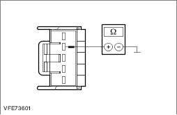
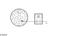
| | 3 Measure the resistance between trailer module, connector C4AT23-C, pin 4, circuit GD152C (BK/BU), wiring harness side and ground. |
| | Is a resistance of less than 2 Ohms registered? Yes RENEW trailer module. CHECK system operates correctly No LOCATE and RECTIFY break in circuit GD152C (BK/BU) between trailer module and soldered connection SP600 using the Wiring Diagrams. CHECK system operates correctly |
| A7: CHECK THE VOLTAGE AT THE TRAILER SOCKET WITH THE STOP LAMPS SWITCHED ON |
NOTE:Keep the brake pedal depressed during the following measurement. |
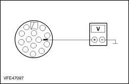
| | 1 Ignition switch in position II. |
| | 2 APPLY the brakes. |
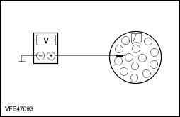
| | 3 Measure the voltage between the trailer socket, connector C4AT23-D, pin 6, circuit CAT19A (VT) and ground. |
| | Does the meter display battery voltage? Yes Continue fault finding on the trailer. No |
| A8: CHECK CIRCUIT CAT19A (VT) BETWEEN TRAILER MODULE AND TRAILER SOCKET FOR OPEN CIRCUIT |
| | 1 Ignition switch in position 0. |
| | 2 Disconnect Trailer module from connector C4AT23-A. |
| | 3 Measure resistance between trailer module, connector C4AT23-A, pin 3, circuit CAT19A (VT), wiring harness side and trailer socket, connector C4AT23-D, pin 6, circuit CAT19A (VT), wiring harness side. |
| | Is a resistance of less than 2 Ohms registered? Yes No LOCATE and RECTIFY break in circuit CAT19A (VT) between trailer module and trailer socket using the Wiring Diagrams. CHECK system operates correctly If necessary RENEW the trailer socket. CHECK system operates correctly |
| A9: CHECK CIRCUIT CAT19A (VT) BETWEEN TRAILER MODULE AND TRAILER SOCKET FOR SHORT TO GROUND |
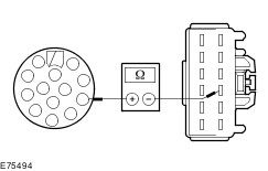
| | 1 Measure the resistance between the trailer socket, connector C4AT23-D, pin 6, circuit CAT19A (VT), wiring harness side and ground. |
| | Is a resistance of more than 10,000 Ohm measured? Yes No LOCATE and RECTIFY the short to ground in the circuit between trailer module and trailer socket with the aid of the wiring diagrams. CHECK system operates correctly If necessary RENEW the trailer socket. CHECK system operates correctly |
| A10: CHECK CIRCUIT BETWEEN GEM AND TRAILER MODULE FOR OPEN CIRCUIT |
NOTE:Keep the brake pedal depressed during the following measurement. |
| | 1 Disconnect Trailer module from connector C4AT23-C. |
| | 2 Ignition switch in position II. |
| | 3 APPLY the brakes. |
| | 4 Measure the voltage between trailer module, connector C4AT23-C, pin 3, circuit CLS44E (VT/BN), wiring harness side and ground. |
| | Does the meter display battery voltage? Yes RENEW trailer module. CHECK system operates correctly No LOCATE and RECTIFY break in circuit CLS44E (VT/BN) between soldered connection SP451 and trailer module using the Wiring Diagrams. CHECK system operates correctly |
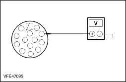
| A11: CHECK THE VOLTAGE AT THE TRAILER SOCKET WITH THE REAR FOG LAMPS SWITCHED ON |
| | 1 Ignition switch in position II. |
| | 2 Switch on the REAR FOG LAMPS. |
| | 3 SWITCH ON the dipped beam. |
| | 4 Measure the voltage between the trailer socket, connector C4AT23-D, pin 2, circuit CAT07A (RD/YE) and ground. |
| | Does the meter display battery voltage? Yes Continue fault finding on the trailer. No |
| A12: CHECK CIRCUIT CAT07A (RD/YE) BETWEEN TRAILER MODULE AND TRAILER SOCKET FOR OPEN CIRCUIT |
| | 1 Ignition switch in position 0. |
| | 2 Disconnect Trailer module from connector C4AT23-A. |
| | 3 Measure the resistance between the trailer module, connector C4AT23-A, pin 8, circuit CAT07A (RD/YE), wiring harness side and the trailer socket, connector C4AT23-D, pin 2, circuit CAT07A (RD/YE), wiring harness side. |
| | Is a resistance of less than 2 Ohms registered? Yes No LOCATE and RECTIFY break in circuit CAT07A (RD/YE) between trailer module and trailer socket using the Wiring Diagrams. CHECK system operates correctly If necessary RENEW the trailer socket. CHECK system operates correctly |
| A13: CHECK CIRCUIT CAT07A (RD/YE) BETWEEN THE TRAILER MODULE AND THE TRAILER SOCKET FOR SHORT TO GROUND |
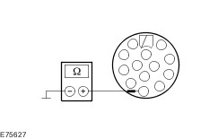
| | 1 Measure the resistance between the trailer socket, connector C4AT23-D, pin 2, circuit CAT07A (RD/YE), wiring harness side and ground. |
| | Is a resistance of more than 10,000 Ohm measured? Yes RENEW trailer module. CHECK system operates correctly No LOCATE and RECTIFY the short to ground in the circuit between trailer module and trailer socket with the aid of the wiring diagrams. CHECK system operates correctly If necessary RENEW the trailer socket. CHECK system operates correctly |
| A14: CHECK THE VOLTAGE AT THE TRAILER SOCKET WITH THE REVERSING LAMPS SWITCHED ON |
| | 1 Ignition switch in position II. |
| | 2 ENGAGE reverse gear. |
| | 3 Measure the voltage between the trailer socket C4AT23-D, pin 8, circuit CAT03A (VT/OG) and ground. |
| | Does the meter display battery voltage? Yes Continue fault finding on the trailer. No |
| A15: CHECK CIRCUIT CAT03A (VT/OG) BETWEEN THE TRAILER MODULE AND THE TRAILER SOCKET FOR OPEN CIRCUIT |
| | 1 Ignition switch in position 0. |
| | 2 Disconnect Trailer module from connector C4AT23-A. |
| | 3 Measure the resistance between the trailer module, connector C4AT23-A, pin 6, circuit CAT03A (VT/OG), wiring harness side and the trailer socket, connector C4AT23-D, pin 8, circuit CAT03A (VT/OG), wiring harness side. |
| | Is a resistance of less than 2 Ohms registered? Yes No LOCATE and RECTIFY break in circuit CAT03A (VT/OG) between trailer module and trailer socket using the Wiring Diagrams. CHECK system operates correctly If necessary RENEW the trailer socket. CHECK system operates correctly |
| A16: CHECK CIRCUIT CAT03A (VT/OG) BETWEEN THE TRAILER MODULE AND THE TRAILER SOCKET FOR SHORT TO GROUND |
| | 1 Measure the resistance between the trailer socket, connector C4AT23-D, pin 8, circuit CAT03A (VT/OG), wiring harness side and ground. |
| | Is a resistance of more than 10,000 Ohm measured? Yes RENEW trailer module. CHECK system operates correctly No LOCATE and RECTIFY the short to ground in the circuit between trailer module and trailer socket with the aid of the wiring diagrams. CHECK system operates correctly If necessary RENEW the trailer socket. CHECK system operates correctly |
| A17: CHECK CIRCUITS CAT11A/B (OG) BETWEEN THE TRAILER MODULE AND THE TRAILER SOCKET FOR SHORT TO GROUND |
| | 1 Ignition switch in position 0. |
| | 2 Disconnect Trailer module from connector C4AT23-A. |
| | 3 Measure the resistance between the trailer module, connector C4AT23-A, pin 12, circuit CAT11A/B (OG), wiring harness side and ground. |
| | Is a resistance of more than 10,000 Ohm measured? Yes RENEW trailer module. CHECK system operates correctly No LOCATE and RECTIFY the short to ground in the circuits connected to the trailer module, connector C4AT23-A, pin 12 with the aid of the Wiring Diagrams. CHECK system operates correctly If necessary RENEW the trailer socket. CHECK system operates correctly |