| Diagnosis and Testing Refer to Wiring Diagrams Section 417-02, for schematic and connector information. Ford approved diagnostic tool Inspection and Verification - Verify the customer concern.
- Visually inspect for obvious signs of electrical damage.
Visual Inspection Chart | Electrical | - Bulb(s)
- Fuse(s)
- Switch(es)
- Wiring harness
- Electrical connector(s)
- Interior lamp(s)
- Battery saver relay
- Central junction box (CJB)
| - If an obvious cause for an observed or reported concern is found, correct the cause (if possible) before proceeding to the next step.
- If the cause is not visually evident, verify the symptom and refer to the Symptom Chart.
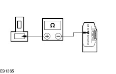
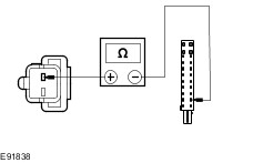
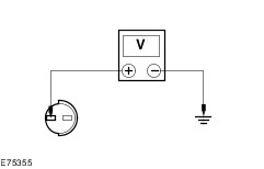
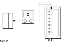
Symptom Chart | Symptom | Possible Sources | Action | | The front interior lamp is inoperative | * Fuse(s). * Bulb(s). * Circuit(s). * Front interior lamp. * Battery saver relay. * CJB. | * | | The rear interior lamp is inoperative | * Fuse(s). * Bulb(s). * Circuit(s). * Middle interior lamp. * Battery saver relay. * CJB. | * | | The luggage compartment roof lamp is inoperative - wagon | * Fuse(s). * Bulb(s). * Circuit(s). * Rear interior lamp. * Battery saver relay. * CJB. | * | | The luggage compartment lamp is inoperative - 4-door and 5-door | * Fuse(s). * Bulb(s). * Circuit(s). * Luggage compartment lamp. * Liftgate latch motor. * CJB. | * | | The glove compartment lamp is inoperative | * Fuse(s). * Bulb(s). * Circuit(s). * Glove compartment lamp. * Battery saver relay. * CJB. | * | | The front footwell lamp(s) are inoperative | * Fuse(s). * Bulb(s). * Circuit(s). * Front footwell lamp(s). * Battery saver relay. * CJB. | * | | The vanity mirror lamp(s) are inoperative | * Fuse(s). * Bulb(s). * Circuit(s). * Vanity mirror lamp(s). * Battery saver relay. * CJB. | * | | The instrument panel auxiliary lighting is inoperative | * Fuse(s). * Bulb(s). * Circuit(s). * Front interior lamp. * Battery saver relay. * CJB. | * | | The battery saver is inoperative/does not operate correctly | * Circuit(s). * Door module(s). * Door ajar switch(es). * CJB. | * Refer to the Ford approved diagnostic tool. | Pinpoint Tests NOTE:Use a digital multimeter for all electrical measurements. | PINPOINT TEST A : THE FRONT INTERIOR LAMP IS INOPERATIVE | | TEST CONDITIONS | DETAILS/RESULTS/ACTIONS | | A1: CHECK OPERATION OF THE INTERIOR LAMP | | | 1 Check for operation of the interior lamp in both the ON and DOOR OPEN positions. | | | Is the interior lamp inoperative in both positions? Yes No If the interior lamp is inoperative in the ON position. GO to A5. If the interior lamp is inoperative in the DOOR OPEN position. GO to A2. | | A2: CHECK CIRCUIT CLN27G (WH/BN) AND CIRCUIT CLN27B (WH/BN) FOR OPEN CIRCUIT | | | 1 Disconnect Front Interior Lamp C9LN28-B. | | | 2 Disconnect CJB C1BP02-H. | | | 3 Measure the resistance between the front interior lamp C9LN28-B pin 1, circuit CLN27G (WH/BN), harness side and the CJB C1BP02-H pin 20, circuit CLN27B (WH/BN), harness side . | | | Is the resistance less than 1 ohm? Yes INSTALL a new front interior lamp. TEST the system for normal operation. No REPAIR the circuit(s) as necessary. TEST the system for normal operation. If the concern persists, INSTALL a new CJB. TEST the system for normal operation. | | A3: CHECK CIRCUIT CBP17A (BN/GN) FOR VOLTAGE | | | 1 Disconnect Front Interior Lamp C9LN28-A. | | | 2 Measure the voltage between the front interior lamp C9LN28-A pin 1, circuit CBP17A (BN/GN), harness side and ground. | | | Is the voltage greater than 10 volts? Yes INSTALL a new front interior lamp. TEST the system for normal operation. If the concern persists, GO to Pinpoint Test I. No | | A4: CHECK FRONT INTERIOR LAMP POWER CIRCUIT FOR OPEN CIRCUIT | | | 1 Disconnect CJB C1BP02-C. | | | 2 Measure the resistance between the front interior lamp C9LN28-A pin 1, circuit CBP17A (BN/GN), harness side and the CJB C1BP02-C pin 67, circuit CBP17R (BN/GN), harness side. | | | Is the resistance less than 1 ohm? Yes No REPAIR circuit CBP17A (BN/GN) or circuit CBP17R (BN/GN) as necessary . TEST the system for normal operation. | | A5: CHECK CIRCUIT GD138R (BK/WH) FOR GROUND | | | 1 Disconnect the battery ground cable.
REFER to: Battery Disconnect and Connect (414-01 Battery, Mounting and Cables, General Procedures).
| | | 2 Disconnect Front Interior Lamp C9LN28-B. | | | 3 Measure the resistance between the front interior lamp C9LN28-B pin 2, circuit GD138R (BK/WH), harness side and ground. | | | Is the resistance less than 1 ohm? Yes INSTALL a new front interior lamp. TEST the system for normal operation. No REPAIR the circuit. TEST the system for normal operation. | | PINPOINT TEST B : THE REAR INTERIOR LAMP IS INOPERATIVE | | TEST CONDITIONS | DETAILS/RESULTS/ACTIONS | | B1: CHECK OPERATION OF THE REAR INTERIOR LAMP | | | 1 Check for operation of the rear interior lamp in both the ON and DOOR OPEN positions. | | | Is the rear interior lamp inoperative in both positions? Yes No If the rear interior lamp is inoperative in the ON position. GO to B5. If the rear interior lamp is inoperative in the DOOR OPEN position. GO to B2. | | B2: CHECK CIRCUIT CLN27H (WH/BN) AND CIRCUIT CLN27B (WH/BN) FOR OPEN CIRCUIT | | | 1 Disconnect Rear Interior Lamp C9LN14-B. | | | 2 Disconnect CJB C1BP02-H. | | | 3 Measure the resistance between the rear interior lamp C9LN14-B pin 1, circuit CLN27H (WH/BN), harness side and the CJB C1BP02-H pin 20, circuit CLN27B (WH/BN), harness side . | | | Is the resistance less than 1 ohm? Yes INSTALL a new rear interior lamp. TEST the system for normal operation. No REPAIR the circuit(s) as necessary. TEST the system for normal operation. If the concern persists, INSTALL a new CJB. TEST the system for normal operation. | | B3: CHECK CIRCUIT CBP17B (BN/GN) FOR VOLTAGE | | | 1 Disconnect Rear Interior Lamp C9LN14-A. | | | 2 Measure the voltage between the rear interior lamp C9LN14-A pin 1, circuit CBP17B (BN/GN), harness side and ground. | | | Is the voltage greater than 10 volts? Yes INSTALL a new rear interior lamp. TEST the system for normal operation. If the concern persists, GO to Pinpoint Test I. No | | B4: CHECK REAR INTERIOR LAMP POWER CIRCUIT FOR OPEN CIRCUIT | | | 1 Disconnect CJB C1BP02-C. | | | 2 Measure the resistance between the rear interior lamp C9LN14-A pin 1, circuit CBP17B (BN/GN), harness side and the CJB C1BP02-C pin 67, circuit CBP17R (BN/GN), harness side. | | | Is the resistance less than 1 ohm? Yes No REPAIR circuit CBP17B (BN/GN) or circuit CBP17R (BN/GN) as necessary . TEST the system for normal operation. | | B5: CHECK CIRCUIT GD138X (BK/WH) FOR GROUND | | | 1 Disconnect the battery ground cable.
REFER to: Battery Disconnect and Connect (414-01 Battery, Mounting and Cables, General Procedures).
| | | 2 Disconnect Rear Interior Lamp C9LN14-B. | | | 3 Measure the resistance between the rear interior lamp C9LN14-B pin 2, circuit GD138X (BK/WH), harness side and ground. | | | Is the resistance less than 1 ohm? Yes INSTALL a new rear interior lamp. TEST the system for normal operation. No REPAIR the circuit. TEST the system for normal operation. | | PINPOINT TEST C : THE LUGGAGE COMPARTMENT LAMP IS INOPERATIVE - WAGON | | TEST CONDITIONS | DETAILS/RESULTS/ACTIONS | | C1: CHECK OPERATION OF THE LUGGAGE COMPARTMENT LAMP | | | 1 Check for operation of the luggage compartment lamp in both the ON and LIFTGATE OPEN positions. | | | Is the luggage compartment lamp inoperative in both positions? Yes No If the luggage compartment lamp is inoperative in the ON position. GO to C5. If the luggage compartment lamp is inoperative in the LIFTGATE OPEN position. GO to C2. | | C2: CHECK THE SWITCHED SIGNAL TO THE LUGGAGE COMPARTMENT LAMP | | | 1 Disconnect Luggage Compartment Lamp C4LN13-G. | | | 2 Disconnect Liftgate Latch Motor C4PL17. | | | 3 Measure the resistance between the luggage compartment lamp C4LN13-G pin 1, circuit CLN13F (WH/BU), harness side and the liftgate latch motor C4PL17 pin 4, circuit CLN13C (BK), harness side . | | | Is the resistance less than 1 ohm? Yes INSTALL a new rear interior lamp. TEST the system for normal operation. No REPAIR the circuit(s) as necessary. TEST the system for normal operation. If the concern persists, INSTALL a new CJB. TEST the system for normal operation. | | C3: CHECK CIRCUIT CBP17C (BN/GN) FOR VOLTAGE | | | 1 Disconnect Luggage Compartment Lamp C4LN13-F. | | | 2 Measure the voltage between the luggage compartment lamp C9LN13-F pin 1, circuit CBP17E (BN/GN), harness side and ground. | | | Is the voltage greater than 10 volts? Yes INSTALL a new luggage compartment lamp. TEST the system for normal operation. If the concern persists, GO to Pinpoint Test I. No | | C4: CHECK LUGGAGE COMPARTMENT LAMP POWER CIRCUIT FOR OPEN CIRCUIT | | | 1 Disconnect CJB C1BP02-C. | | | 2 Measure the resistance between the luggage compartment lamp C9LN13-F pin 1, circuit CBP17E (BN/GN), harness side and the CJB C1BP02-C pin 67, circuit CBP17R (BN/GN), harness side. | | | Is the resistance less than 1 ohm? Yes No REPAIR circuit CBP17C (BN/GN) or circuit CBP17R (BN/GN) as necessary. TEST the system for normal operation. | | C5: CHECK CIRCUIT GD138U (BK/WH) FOR GROUND | | | 1 Disconnect the battery ground cable.
REFER to: Battery Disconnect and Connect (414-01 Battery, Mounting and Cables, General Procedures).
| | | 2 Disconnect Luggage Compartment Lamp C4LN13-G. | | | 3 Measure the resistance between the luggage compartment lamp C4LN13-G pin 2, circuit GD138U (BK/WH), harness side and ground. | | | Is the resistance less than 1 ohm? Yes INSTALL a new luggage compartment lamp. TEST the system for normal operation. No REPAIR the circuit. TEST the system for normal operation. | | PINPOINT TEST D : THE LUGGAGE COMPARTMENT LAMP IS INOPERATIVE - 4-DOOR AND 5-DOOR | | TEST CONDITIONS | DETAILS/RESULTS/ACTIONS | | D1: CHECK CIRCUIT CBP17B (BN/GN) FOR VOLTAGE | | | 1 Ignition switch in position 0. | | | 2 Disconnect Luggage Compartment Lamp C4LN13-H. | | | 3 Measure the voltage between the luggage compartment lamp C4LN13-H pin 1, circuit CBP17B (BN/GN), harness side and ground. | | | Is the voltage greater than 10 volts? Yes No | | D2: CHECK LUGGAGE COMPARTMENT LAMP POWER CIRCUIT FOR OPEN CIRCUIT | | | 1 Disconnect CJB C1BP02-B. | | | 2 Measure the resistance between the luggage compartment lamp C4LN13-H pin 1, circuit CBP17B (BN/GN), harness side and the CJB C1BP02-B pin 56, circuit A_CBP17A (BN/GN), harness side. | | | Is the resistance less than 1 ohm? Yes No REPAIR circuit CBP17B (BN/GN) or circuit A_CBP17A (BN/GN) as necessary . TEST the system for normal operation. | | D3: CHECK THE SWITCHED SIGNAL TO THE LUGGAGE COMPARTMENT LAMP | | | 1 Disconnect Liftgate Latch Motor C4PL17. | | | 2 Measure the resistance between the luggage compartment lamp C4LN13-H pin 2, circuit CLN13B (WH/BU), harness side and the liftgate latch motor C4PL17 pin 4, circuit CLN13C (WH/BU), harness side. | | | Is the resistance less than 1 ohm? Yes INSTALL a new luggage compartment lamp. TEST the system for normal operation. If the concern persists, GO to D4. No REPAIR circuit CLN13B (WH/BU) or circuit CLN13C (WH/BU) as necessary . TEST the system for normal operation. | | D4: CHECK THE LIFTGATE LATCH MOTOR FOR GROUND | | | 1 Measure the resistance between the liftgate latch motor C4PL17 pin 2, circuit GD150Y (BK/WH), harness side and ground. | | | Is the resistance less than 5 ohms? Yes INSTALL a new liftgate latch motor.
REFER to: Liftgate Latch (501-14 Handles, Locks, Latches and Entry Systems, Removal and Installation).
TEST the system for normal operation. No REPAIR the circuit GD150Y (BK/WH). TEST the system for normal operation. | | PINPOINT TEST E : THE GLOVE COMPARTMENT LAMP IS INOPERATIVE | | TEST CONDITIONS | DETAILS/RESULTS/ACTIONS | | E1: CHECK CIRCUIT CBP17N (BN/GN) FOR VOLTAGE | | | 1 Disconnect Glove Compartment Lamp C2LN15. | | | 2 Measure the voltage between the glove compartment lamp C2LN15 pin 1, circuit CBP17N (BN/GN), harness side and ground. | | | Is the voltage greater than 10 volts? Yes No | | E2: CHECK THE GLOVE COMPARTMENT LAMP POWER CIRCUIT FOR OPEN CIRCUIT | | | 1 Disconnect CJB C1BP02-C. | | | 2 Measure the resistance between the glove compartment lamp C2LN15 pin 1, circuit CBP17N (BN/GN), harness side and the CJB C1BP02-C pin 67, circuit CBP17R (BN/GN), harness side. | | | Is the resistance less than 1 ohm? Yes No REPAIR circuit CLN15 pin 1, circuit CBP17N (BN/GN) or circuit CBP17R (BN/GN) as necessary. TEST the system for normal operation. | | E3: CHECK CIRCUIT GD138AU (BK/WH) FOR GROUND | | | 1 Measure the resistance between the glove compartment lamp C2LN15 pin 2, circuit GD138AU (BK/WH), harness side and ground. | | | Is the resistance less than 1 ohm? Yes INSTALL a new glove compartment lamp. TEST the system for normal operation. No REPAIR the circuit. TEST the system for normal operation. | | PINPOINT TEST F : THE FRONT FOOTWELL LAMP(S) ARE INOPERATIVE | | TEST CONDITIONS | DETAILS/RESULTS/ACTIONS | | F1: CHECK OPERATION OF THE FOOTWELL LAMPS | | | 1 Check for operation of the front footwell lamp(s). | | | Are both the front footwell lamp(s) inoperative? Yes No If the right-hand side front footwell lamp is inoperative. GO to F5. If the left-hand side front footwell lamp is inoperative. GO to F2. | | F2: CHECK CIRCUIT CBP17H (BN/WH) FOR VOLTAGE | | | 1 Disconnect Left-hand Front Footwell Lamp C3LN38. | | | 2 Measure the voltage between the left-hand front footwell lamp C3LN38 pin 1, circuit CBP17H (BN/GN), harness side and ground. | | | Is the voltage greater than 10 volts? Yes No | | F3: CHECK THE LEFT-HAND FRONT FOOTWELL LAMP POWER CIRCUIT FOR OPEN CIRCUIT | | | 1 Disconnect CJB C1BP02-C. | | | 2 Measure the resistance between the left-hand front footwell lamp C3LN38 pin 1, circuit CBP17H (BN/GN), harness side and the CJB C1BP02-C pin 67, circuit CBP17R (BN/GN), harness side. | | | Is the resistance less than 1 ohm? Yes No REPAIR circuit CBP17H (BN/GN) or circuit CBP17R (BN/GN) as necessary. TEST the system for normal operation. If the concern persists, INSTALL a new left-hand front footwell lamp. TEST the system for normal operation. | | F4: CHECK CIRCUIT CLN38A (BU/GY) FOR OPEN CIRCUIT | | | 1 Disconnect CJB C1BP02-C. | | | 2 Measure the resistance between the left-hand front footwell lamp C3LN38 pin 2, circuit CLN38A (BU/GY), harness side and the CJB C1BP02-C pin 19, circuit CLN38A (BU/GY), harness side. | | | Is the resistance less than 1 ohm? Yes REFER to the Ford approved diagnostic tool. No REPAIR the circuit. TEST the system for normal operation. If the concern persists, INSTALL a new left-hand front footwell lamp. TEST the system for normal operation. | | F5: CHECK CIRCUIT CBP17L (BN/GN) FOR VOLTAGE | | | 1 Disconnect Right-hand Front Footwell Lamp C3LN39. | | | 2 Measure the voltage between the right-hand front footwell lamp C3LN39 pin 1, circuit CBP17L (BN/GN), harness side and ground. | | | Is the voltage greater than 10 volts? Yes No | | F6: CHECK THE RIGHT-HAND FRONT FOOTWELL LAMP POWER CIRCUIT FOR OPEN CIRCUIT | | | 1 Disconnect CJB C1BP02-C. | | | 2 Measure the resistance between the right-hand front footwell lamp C3LN39 pin 1, circuit CBP17L (BN/GN), harness side and the CJB C1BP02-C pin 67, circuit CBP17R (BN/GN), harness side. | | | Is the resistance less than 1 ohm? Yes REFER to the Ford approved diagnostic tool. No REPAIR circuit CBP17L (BN/GN) or circuit CBP17R (BN/GN) as necessary. TEST the system for normal operation. If the concern persists, INSTALL a new right-hand front footwell lamp. TEST the system for normal operation. | | F7: CHECK CIRCUIT CLN38C (BU/WH) FOR OPEN CIRCUIT | | | 1 Disconnect CJB C1BP02-C. | | | 2 Measure the resistance between the right-hand front footwell lamp C3LN39 pin 2, circuit CLN38C (BU/WH), harness side and the CJB C1BP02-C pin 37, circuit CLN38C (BU/WH), harness side. | | | Is the resistance less than 1 ohm? Yes REFER to the Ford approved diagnostic tool. No REPAIR the circuit. TEST the system for normal operation. If the concern persists, INSTALL a new right-hand front footwell lamp. TEST the system for normal operation. | | PINPOINT TEST G : THE VANITY MIRROR LAMP(S) ARE INOPERATIVE | | TEST CONDITIONS | DETAILS/RESULTS/ACTIONS | | G1: CHECK OPERATION OF THE VANITY MIRROR LAMP | | | 1 Check for operation of the vanity mirror lamp(s). | | | Are both the vanity mirror lamp(s) inoperative? Yes No If the driver side vanity mirror lamp is inoperative. GO to G2. If the passenger side vanity mirror lamp is inoperative. GO to G5. | | G2: CHECK CIRCUIT CBP17D (BN/GN) FOR VOLTAGE | | | 1 Disconnect Driver Side Vanity Mirror Lamp C5LN23. | | | 2 Measure the voltage between the driver side vanity mirror lamp C5LN23 pin 1, circuit CBP17D (BN/GN), harness side and ground. | | | Is the voltage greater than 10 volts? Yes No | | G3: CHECK THE DRIVER SIDE VANITY MIRROR LAMP POWER CIRCUIT FOR OPEN CIRCUIT | | | 1 Disconnect CJB C1BP02-C. | | | 2 Measure the resistance between the driver side vanity mirror lamp C5LN23 pin 1, circuit CBP17D (BN/GN), harness side and the CJB C1BP02-C pin 67, circuit CBP17R (BN/GN), harness side. | | | Is the resistance less than 1 ohm? Yes No REPAIR circuit CBP17D (BN/GN) or circuit CBP17R (BN/GN) as necessary. TEST the system for normal operation. If the concern persists, INSTALL a new driver side vanity mirror lamp. TEST the system for normal operation. | | G4: CHECK CIRCUIT GD138AF (BK/WH) FOR GROUND | | | 1 Measure the resistance between the driver side vanity mirror lamp C5LN23 pin 3, circuit GD138AF (BK/WH), harness side and ground. | | | Is the resistance less than 1 ohm? Yes INSTALL a new driver side vanity mirror lamp. TEST the system for normal operation No REPAIR the circuit. TEST the system for normal operation. | | G5: CHECK CIRCUIT CBP17F (BN/GN) FOR VOLTAGE | | | 1 Disconnect Passenger Side Vanity Mirror Lamp C6LN24. | | | 2 Measure the voltage between the passenger side vanity mirror lamp C6LN24 pin 1, circuit CBP17F (BN/GN), harness side and ground. | | | Is the voltage greater than 10 volts? Yes No | | G6: CHECK THE PASSENGER SIDE VANITY MIRROR LAMP POWER CIRCUIT FOR OPEN CIRCUIT | | | 1 Disconnect CJB C1BP02-C. | | | 2 Measure the resistance between the passenger side vanity mirror lamp C6LN24 pin 1, circuit CBP17F (BN/GN), harness side and the CJB C1BP02-C pin 67, circuit CBP17R (BN/GN), harness side. | | | Is the resistance less than 1 ohm? Yes No REPAIR the circuit CBP17F (BN/GN) or circuit CBP17R (BN/GN) as necessary. TEST the system for normal operation. If the concern persists, INSTALL a new passenger side vanity mirror lamp. TEST the system for normal operation. | | G7: CHECK CIRCUIT GD138AH (BK/WH) FOR GROUND | | | 1 Measure the resistance between the passenger side vanity mirror lamp C6LN24 pin 3, circuit GD138AH (BK/WH), harness side and ground. | | | Is the resistance less than 1 ohm? Yes INSTALL a new passenger side vanity mirror lamp. TEST the system for normal operation No REPAIR the circuit. TEST the system for normal operation. | | PINPOINT TEST H : THE INSTRUMENT PANEL AUXILIARY LIGHTING IS INOPERATIVE | | TEST CONDITIONS | DETAILS/RESULTS/ACTIONS | | H1: CHECK CIRCUIT CLN27G (WH/BN) AND CIRCUIT CLN27B (WH/BN) FOR OPEN CIRCUIT | | | 1 Disconnect Front Interior Lamp C9LN28-A. | | | 2 Measure the voltage between the front interior lamp C9LN28-A pin 1, circuit CBP17A (BN/GN), harness side and ground. | | | Is the voltage greater than 10 volts? Yes INSTALL a new front interior lamp. TEST the system for normal operation. If the concern persists, GO to Pinpoint Test I. No | | H2: CHECK CIRCUIT CLN17E (BN) AND CIRCUIT CLN17G (BN) FOR OPEN CIRCUIT | | | 1 Disconnect Front Interior Lamp C9LN28-C. | | | 2 Disconnect CJB C1BP02-C. | | | 3 Measure the resistance between the front interior lamp C9LN28-C pin 1, circuit CLN17-E (BN), harness side and the CJB C1BP02-C pin 54, circuit CLN17G (BN), harness side. | | | Is the resistance less than 1 ohm? Yes INSTALL a new front interior lamp. TEST the system for normal operation. If the concern persists, GO to Pinpoint Test I. No REPAIR the circuit(s) as necessary. TEST the system for normal operation. | | PINPOINT TEST I : BATTERY SAVER RELAY TEST | | TEST CONDITIONS | DETAILS/RESULTS/ACTIONS | | I1: CHECK THE BATTERY SAVER RELAY | | | 1 Disconnect CJB C1BP02-C. | | | 2 Ignition switch in position II. | | | 3 Measure the voltage between the CJB C1BP02-C pin 67, component side and ground. | | | Is the voltage greater than 10 volts? Yes No INSTALL a new CJB. TEST the system for normal operation. | | I2: CHECK THE BATTERY SAVER RELAY DISCHARGE | | | 1 Ignition switch in position 0. | | | 2 WAIT for 35 minutes. | | | 3 Measure the voltage between the CJB C1BP02-C pin 67, component side and ground. | | | Is the voltage 0 volts? Yes CONNECT the CJB C1BP02-C. TEST the system for normal operation. If the concern persists, INSTALL a new CJB. TEST the system for normal operation. No INSTALL a new CJB. TEST the system for normal operation. | |