| Diagnosis and Testing Special Tool(s) | | Terminal Probe Kit 418-S035 | General Equipment Digital multimeter Diagnostic Tool Inspection and Testing - VERIFY the customer concern.
- Visually CHECK for any obvious mechanical or electrical damage.
NOTE:Ensure correct locking of wiring harness connector. Visual Inspection | Electrical | | Fuses. | | Wiring harness. | | Electrical connectors. | - RECTIFY any obvious causes for a concern found during the visual inspection before performing any further tests. CHECK the operation of the system.
- If the concern persists after the visual inspection, PERFORM a fault diagnosis with the diagnostic unit, RECTIFY any displayed faults in accordance with the displayed fault description and then DELETE the displayed fault(s). CHECK the operation of the system.
- For vehicles with no stored fault(s), PROCEED in accordance with the Symptom Chart according to the fault symptom.
- Following checking or elimination of the fault and after completion of operations, the fault memories of all vehicle modules must be READ OUT and any stored faults must be DELETED. READ OUT all fault memories again following a road test.
DTC Index | DTC | Description | Action | | B118929 | Signal error, position sensor for the front electric window regulator | REFER to: Fenster, Rahmen und Betätigungsmechanismen (501-11, Diagnosis and Testing). | | B118A29 | Signal error, position sensor for the rear electric window regulator | REFER to: Fenster, Rahmen und Betätigungsmechanismen (501-11, Diagnosis and Testing). | | C1B1415 | Circuit of the position sensor for the front electric window regulator defective (short to voltage or open circuit). | REFER to: Fenster, Rahmen und Betätigungsmechanismen (501-11, Diagnosis and Testing). | | C1B1411 | Circuit of the position sensor for the front electric window regulator defective (short to ground). | REFER to: Fenster, Rahmen und Betätigungsmechanismen (501-11, Diagnosis and Testing). | | C1B1515 | Circuit of the position sensor for the front electric window regulator defective (short to voltage or open circuit). | REFER to: Fenster, Rahmen und Betätigungsmechanismen (501-11, Diagnosis and Testing). | | C1B1511 | Circuit of the position sensor for the front electric window regulator defective (short to ground). | REFER to: Fenster, Rahmen und Betätigungsmechanismen (501-11, Diagnosis and Testing). | | B1C1315 | Circuit for up/down adjustment of the motor for the electrically adjustable exterior mirror on the driver's side faulty (short to ground). | REFER to: Außenspiegel (501-09, Diagnosis and Testing). | | B1C1311 | Circuit for up/down adjustment of the motor for the electrically adjustable exterior mirror on the driver's side faulty (short to voltage or open circuit). | REFER to: Außenspiegel (501-09, Diagnosis and Testing). | | B1C1415 | Circuit for left/right adjustment of the motor for the electrically adjustable exterior mirror on the driver's side faulty (short to ground). | REFER to: Außenspiegel (501-09, Diagnosis and Testing). | | B1C1411 | Circuit for left/right adjustment of the motor for the electrically adjustable exterior mirror on the driver's side faulty (short to voltage or open circuit). | REFER to: Außenspiegel (501-09, Diagnosis and Testing). | | B1C1515 | Circuit for up/down adjustment of the motor for the electrically adjustable exterior mirror on the passenger side faulty (short to ground). | REFER to: Außenspiegel (501-09, Diagnosis and Testing). | | B1C1511 | Circuit for up/down adjustment of the motor for the electrically adjustable exterior mirror on the passenger side faulty (short to voltage or open circuit). | REFER to: Außenspiegel (501-09, Diagnosis and Testing). | | B1C1615 | Circuit for left/right adjustment of the motor for the electrically adjustable exterior mirror on the passenger side faulty (short to ground). | REFER to: Außenspiegel (501-09, Diagnosis and Testing). | | B1C1611 | Circuit for left/right adjustment of the motor for the electrically adjustable exterior mirror on the passenger side faulty (short to voltage or open circuit). | REFER to: Außenspiegel (501-09, Diagnosis and Testing). | | U210000, U201208,U300281 | Module configuration faulty. | Make sure that the latest release of the software is loaded in the diagnostic unit and that the correct variant is installed. CONFIGURE the driver's door module again using the diagnostic unit. If the fault occurs again, RENEW driver's door module. | | U201444, U300049, U030000 | Internal control unit fault. | Make sure that the latest release of the software is loaded in the diagnostic unit and that the correct variant is installed. CONFIGURE the driver's door module again using the diagnostic unit. If the fault occurs again, RENEW driver's door module. | | B117E73 | Circuit of the front electric window regulator faulty (window cannot be closed). | REFER to: Fenster, Rahmen und Betätigungsmechanismen (501-11, Diagnosis and Testing). | | B117E72 | Circuit of the front electric window regulator faulty (window cannot be closed). | REFER to: Fenster, Rahmen und Betätigungsmechanismen (501-11, Diagnosis and Testing). | | B117E07 | Circuit of the front electric window regulator faulty (mechanical fault). | REFER to: Fenster, Rahmen und Betätigungsmechanismen (501-11, Diagnosis and Testing). | | B117F73 | Circuit of the front electric window regulator faulty (window cannot be opened). | REFER to: Fenster, Rahmen und Betätigungsmechanismen (501-11, Diagnosis and Testing). | | B117F72 | Circuit of the front electric window regulator faulty (window cannot be opened). | REFER to: Fenster, Rahmen und Betätigungsmechanismen (501-11, Diagnosis and Testing). | | B117C73 | Circuit of the rear electric window regulator faulty (window cannot be closed). | REFER to: Fenster, Rahmen und Betätigungsmechanismen (501-11, Diagnosis and Testing). | | B117C72 | Circuit of the rear electric window regulator faulty (window cannot be closed). | REFER to: Fenster, Rahmen und Betätigungsmechanismen (501-11, Diagnosis and Testing). | | B117C07 | Circuit of the rear electric window regulator faulty (mechanical fault). | REFER to: Fenster, Rahmen und Betätigungsmechanismen (501-11, Diagnosis and Testing). | | B117D73 | Circuit of the rear electric window regulator faulty (window cannot be opened). | REFER to: Fenster, Rahmen und Betätigungsmechanismen (501-11, Diagnosis and Testing). | | B117D72 | Circuit of the rear electric window regulator faulty (window cannot be opened). | REFER to: Fenster, Rahmen und Betätigungsmechanismen (501-11, Diagnosis and Testing). | | B110811 | Circuit of left-hand central locking motor faulty (short to ground). | GO to Pinpoint Test D. | | B110815 | Circuit of left-hand central locking motor faulty (short to voltage or open circuit). | GO to Pinpoint Test D. | | B10EB11 | Circuit of left-hand central locking motor with double locking faulty (short to ground). | GO to Pinpoint Test E. | | B10EB15 | Circuit of left-hand central locking motor with double locking faulty (short to voltage or open circuit). | GO to Pinpoint Test E. | | U201324 | Driver's door switch unit faulty. | REFER to: Fenster, Rahmen und Betätigungsmechanismen (501-11, Diagnosis and Testing). | | U200224 | Passenger door switch unit faulty. | REFER to: Fenster, Rahmen und Betätigungsmechanismen (501-11, Diagnosis and Testing). | | U200424 | Rear door switch unit faulty, driver's side/passenger side | REFER to: Fenster, Rahmen und Betätigungsmechanismen (501-11, Diagnosis and Testing). | | B110911 | Circuit of right-hand central locking motor faulty (short to ground). | GO to Pinpoint Test C. | | B110915 | Circuit of right-hand central locking motor faulty (short to voltage or open circuit). | GO to Pinpoint Test C. | | B10EC11 | Circuit of right-hand central locking motor with double locking faulty (short to ground). | GO to Pinpoint Test F. | | B10EC15 | Circuit of right-hand central locking motor with double locking faulty (short to voltage or open circuit). | GO to Pinpoint Test F. | | B110A11 | Circuit of left-hand rear central locking motor faulty (short to ground). | GO to Pinpoint Test H. | | B110A15 | Circuit of left-hand rear central locking motor faulty (short to voltage or open circuit). | GO to Pinpoint Test H. | | B11ED11 | Circuit of left-hand rear central locking motor with double locking faulty (short to ground). | GO to Pinpoint Test I. | | B11ED15 | Circuit of central locking motor with double locking faulty, driver's side rear left (short to voltage or open circuit). | GO to Pinpoint Test I. | | B110B11 | Circuit of right-hand rear central locking motor faulty (short to ground). | GO to Pinpoint Test G. | | B110B15 | Circuit of right-hand rear central locking motor faulty (short to voltage or open circuit). | GO to Pinpoint Test G. | | B11EE11 | Circuit of right-hand rear central locking motor with double locking faulty (short to ground). | GO to Pinpoint Test J. | | B11EE15 | Circuit of right-hand rear central locking motor with double locking faulty (short to voltage or open circuit). | GO to Pinpoint Test J. | | B108F23 | Circuit of the passenger compartment locking switch faulty. | GO to Pinpoint Test K. | | B1C1011 | Circuit of the motor for the electrically adjustable exterior mirror on the drivers's side faulty (short to ground). | REFER to: Außenspiegel (501-09, Diagnosis and Testing). | | B1C0911 | Circuit of the motor for the electrically adjustable exterior mirror on the drivers's side faulty (short to ground). | REFER to: Außenspiegel (501-09, Diagnosis and Testing). | | B1C1111 | Circuit of the motor for the electrically adjustable exterior mirror on the passenger side faulty (short to ground). | REFER to: Außenspiegel (501-09, Diagnosis and Testing). | | B1C1211 | Circuit of the motor for the electrically adjustable exterior mirror on the passenger side faulty (short to ground). | REFER to: Außenspiegel (501-09, Diagnosis and Testing). | | B116311 | Circuit of left-hand heated exterior mirror faulty (short to ground). | REFER to: Außenspiegel (501-09, Diagnosis and Testing). | | B116315 | Circuit of left-hand heated exterior mirror faulty (short to voltage or open circuit). | REFER to: Außenspiegel (501-09, Diagnosis and Testing). | | B116411 | Circuit of right-hand heated exterior mirror faulty (short to ground). | REFER to: Außenspiegel (501-09, Diagnosis and Testing). | | B116415 | Circuit of right-hand heated exterior mirror faulty (short to voltage or open circuit). | REFER to: Außenspiegel (501-09, Diagnosis and Testing). | | B116515 | Circuit of courtesy lamps integrated in the left-hand exterior mirror faulty (short to voltage or open circuit). | REFER to: Parkleuchten, Rückleuchten, Kennzeichenleuchten (417-01, Diagnosis and Testing). | | B116511 | Circuit of courtesy lamps integrated in the left-hand exterior mirror faulty (short to ground). | REFER to: Parkleuchten, Rückleuchten, Kennzeichenleuchten (417-01, Diagnosis and Testing). | | B116515 | Circuit of courtesy lamps integrated in the right-hand exterior mirror faulty (short to voltage or open circuit). | REFER to: Parkleuchten, Rückleuchten, Kennzeichenleuchten (417-01, Diagnosis and Testing). | | B116511 | Circuit of courtesy lamps integrated in the right-hand exterior mirror faulty (short to ground). | REFER to: Parkleuchten, Rückleuchten, Kennzeichenleuchten (417-01, Diagnosis and Testing). | | B109C15 | Circuit of interior lighting activation switch faulty (short to ground or open circuit). | REFER to: Innenbeleuchtung (417-02, Diagnosis and Testing). | | B109C11 | Circuit of interior lighting activation switch faulty (short to ground). | REFER to: Innenbeleuchtung (417-02, Diagnosis and Testing). | | B116115 | Circuit of rear left-hand side window anti-trap protection switch faulty (short to voltage or open circuit). | REFER to: Fenster, Rahmen und Betätigungsmechanismen (501-11, Diagnosis and Testing). | | B116123 | Circuit of rear left-hand side window anti-trap protection switch faulty (signal error). | REFER to: Fenster, Rahmen und Betätigungsmechanismen (501-11, Diagnosis and Testing). | | B116215 | Circuit of rear right-hand side window anti-trap protection switch faulty (short to voltage or open circuit). | REFER to: Fenster, Rahmen und Betätigungsmechanismen (501-11, Diagnosis and Testing). | | B116223 | Circuit of rear right-hand side window anti-trap protection switch faulty (signal error). | REFER to: Fenster, Rahmen und Betätigungsmechanismen (501-11, Diagnosis and Testing). | | B1D0615 | Circuit of turn signal lamp integrated in the left-hand exterior mirror faulty (short to voltage or open circuit). | REFER to: Blinkleuchten/seitliche Blinkleuchten/Warnblinkleuchten (417-01, Diagnosis and Testing). | | B1D0611 | Circuit of turn signal lamp integrated in the left-hand exterior mirror faulty (short to ground). | REFER to: Blinkleuchten/seitliche Blinkleuchten/Warnblinkleuchten (417-01, Diagnosis and Testing). | | B1D0715 | Circuit of turn signal lamp integrated in the right-hand exterior mirror faulty (short to voltage or open circuit). | REFER to: Blinkleuchten/seitliche Blinkleuchten/Warnblinkleuchten (417-01, Diagnosis and Testing). | | B1D0711 | Circuit of turn signal lamp integrated in the right-hand exterior mirror faulty (short to ground). | REFER to: Blinkleuchten/seitliche Blinkleuchten/Warnblinkleuchten (417-01, Diagnosis and Testing). | | B1A9411 | Circuit of driver's side exterior mirror faulty (short to ground). | REFER to: Außenspiegel (501-09, Diagnosis and Testing). | | B1A9415 | Circuit of driver's side exterior mirror faulty (short to voltage or open circuit). | REFER to: Außenspiegel (501-09, Diagnosis and Testing). | | B1A9515 | Circuit of passenger side exterior mirror faulty (short to voltage or open circuit). | REFER to: Außenspiegel (501-09, Diagnosis and Testing). | | B1A9511 | Circuit of passenger side exterior mirror faulty (short to ground). | REFER to: Außenspiegel (501-09, Diagnosis and Testing). | | U300362 | Voltage supply (term. 30) faulty. | GO to Pinpoint Test A. | | B1A9886, B1A9883, B1A9887, B1B7086, B1B7083, B1B7087 | No communications possible via the LIN bus | REFER to: Kommunikations-Netzwerk (418-00, Diagnosis and Testing). | | U001000 | No communications possible via the MS CAN bus. | REFER to: Kommunikations-Netzwerk (418-00, Diagnosis and Testing). | Symptom chart Symptom chart | Symptom | Possible Sources | Action | | Driver's door module not communicating with the diagnostic unit. | * Fuse(s). * Circuit(s). * Driver's door module. | * REFER to: Kommunikations-Netzwerk (418-00, Diagnosis and Testing). | | Passenger's door module not communicating with the diagnostic unit. | * Fuse(s). * Circuit(s). * Passenger door module. | * REFER to: Kommunikations-Netzwerk (418-00, Diagnosis and Testing). | | Voltage supply (terminal 30) at the driver's door module faulty. | * Fuse(s). * Circuit(s). * Driver's door module. | * | | Voltage supply (terminal 30) at the passenger's door module faulty. | * Fuse(s). * Circuit(s). * Passenger door module. | * | Pinpoint test | PINPOINT TEST A : VOLTAGE SUPPLY (TERMINAL 30) AT THE DRIVER'S DOOR MODULE FAULTY. | WARNING:The window anti-trap function will not operate during the window motor initialization procedure. | NOTE:If the power to a window regulator motor has been disconnected, it is necessary to initialize that window regulator motor.
REFER to: Fensterhebermotor initialisieren (501-11, General Procedures).
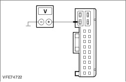
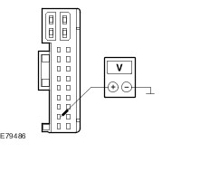
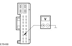
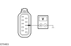
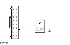
| | TEST CONDITIONS | DETAILS/RESULTS/ACTIONS | | A1: DETERMINE THE VEHICLE VARIANT. | | | 1 Determine the vehicle variant. | | | Is the vehicle LHD? Yes No | | A2: CHECK FUSE FA1 | | | 1 Ignition switch in position 0. | | | 2 CHECK Fuse FA1 (RJB). | | | Is the fuse OK? Yes No RENEW fuse FA1 (25 A). CHECK the operation of the system. If the fuse blows again, LOCATE and REPAIR the short using the Wiring Diagrams. | | A3: CHECK THE VOLTAGE AT FUSE FA1 | | | 1 Connect Fuse FA1 (RJB). | | | 2 Measure the voltage between fuse FA1 (25 A) and ground. | | | Does the meter display battery voltage? Yes No REPAIR the voltage supply to fuse FA1 with the aid of the wiring diagrams. CHECK the operation of the system. | | A4: CHECK FUSE FA2 | | | 1 CHECK Fuse FA2 (RJB). | | | Is the fuse OK? Yes No RENEW fuse FA2 (25 A). CHECK the operation of the system. If the fuse blows again, LOCATE and REPAIR the short using the Wiring Diagrams. | | A5: CHECK THE VOLTAGE AT FUSE FA2 | | | 1 Connect Fuse FA2 (RJB). | | | 2 Measure the voltage between fuse FA2 (25 A) and ground. | | | Does the meter display battery voltage? Yes No REPAIR the voltage supply to fuse FA2 with the aid of the wiring diagrams. CHECK the operation of the system. | | A6: CHECK THE VOLTAGE AT THE DRIVER'S DOOR MODULE. | | | 1 Disconnect Connector C5PL01-A from the driver's door module. | | | 2 Measure the voltage between the driver's door module, connector C5PL01-A, pin 2, circuit SBR01A (RD), wiring harness side and ground. | | | Does the meter display battery voltage? Yes CHECK the driver's door module and RENEW if necessary. CHECK the operation of the system. No LOCATE and RECTIFY the break in the circuit between the driver's door module and fuse FA1 (RHD vehicles: fuse FA2) with the aid of the Wiring Diagrams. CHECK the operation of the system. | | PINPOINT TEST B : VOLTAGE SUPPLY (TERMINAL 30) AT THE PASSENGER'S DOOR MODULE FAULTY. | WARNING:The window anti-trap function will not operate during the window motor initialization procedure. | NOTE:If the power to a window regulator motor has been disconnected, it is necessary to initialize that window regulator motor.
REFER to: Fensterhebermotor initialisieren (501-11, General Procedures).
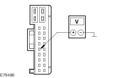
| | TEST CONDITIONS | DETAILS/RESULTS/ACTIONS | | B1: DETERMINE THE VEHICLE VARIANT. | | | 1 Determine the vehicle variant. | | | Is the vehicle LHD? Yes No | | B2: CHECK FUSE FA1 | | | 1 Ignition switch in position 0. | | | 2 CHECK Fuse FA1 (RJB). | | | Is the fuse OK? Yes No RENEW fuse FA1 (25 A). CHECK the operation of the system. If the fuse blows again, LOCATE and REPAIR the short using the Wiring Diagrams. | | B3: CHECK THE VOLTAGE AT FUSE FA1 | | | 1 Connect Fuse FA1 (RJB). | | | 2 Measure the voltage between fuse FA1 (25 A) and ground. | | | Does the meter display battery voltage? Yes No REPAIR the voltage supply to fuse FA1 with the aid of the wiring diagrams. CHECK the operation of the system. | | B4: CHECK FUSE FA2 | | | 1 CHECK Fuse FA2 (RJB). | | | Is the fuse OK? Yes No RENEW fuse FA2 (25 A). CHECK the operation of the system. If the fuse blows again, LOCATE and REPAIR the short using the Wiring Diagrams. | | B5: CHECK THE VOLTAGE AT FUSE FA2 | | | 1 Connect Fuse FA2 (RJB). | | | 2 Measure the voltage between fuse FA2 (25 A) and ground. | | | Does the meter display battery voltage? Yes No REPAIR the voltage supply to fuse FA2 with the aid of the wiring diagrams. CHECK the operation of the system. | | B6: CHECK THE VOLTAGE AT THE PASSENGER'S DOOR MODULE | | | 1 Disconnect Connector C6PL01-A from the passenger's door module. | | | 2 Measure the voltage between the passenger's door module, connector C6PL01-A, pin 2, circuit SBR02A (RD), wiring harness side and ground. | | | Does the meter display battery voltage? Yes CHECK the passenger's door module and RENEW if necessary. CHECK the operation of the system. No LOCATE and RECTIFY the break in the circuit between the passenger's door module and fuse FA2 (RHD vehicles: fuse FA1) with the aid of the Wiring Diagrams. CHECK the operation of the system. | | PINPOINT TEST C : CIRCUIT OF THE RIGHT-HAND CENTRAL LOCKING MOTOR FAULTY. | WARNING:The window anti-trap function will not operate during the window motor initialization procedure. | NOTE:If the power to a window regulator motor has been disconnected, it is necessary to initialize that window regulator motor.
REFER to: Fensterhebermotor initialisieren (501-11, General Procedures).
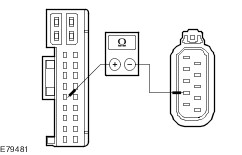
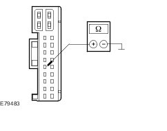
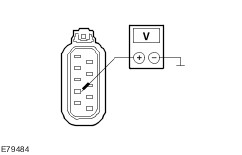
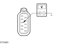
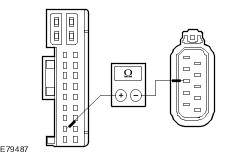
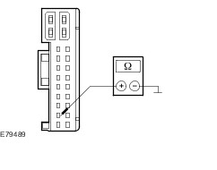
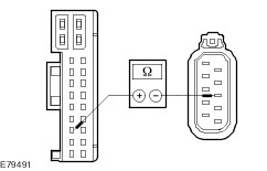
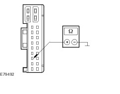
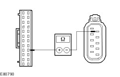
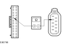
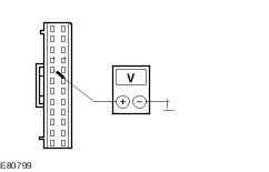
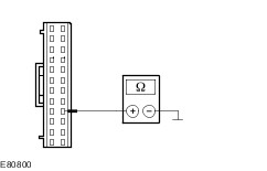
| | TEST CONDITIONS | DETAILS/RESULTS/ACTIONS | | C1: CHECK FOR SHORT TO VOLTAGE IN THE CIRCUIT BETWEEN THE RIGHT-HAND DOOR MODULE AND THE DLC (SCP BUS) | | | 1 Disconnect Connector C6PL01-A from the right-hand door module. | | | 2 Disconnect Connector C6PL64 from the right-hand door lock. | | | 3 Ignition switch in position II. | | | 4 Measure the voltage between the right-hand door module, connector C6PL01-A, pin 7, circuit CPL66A (BK)(RHD vehicles: circuit CPL66AA (BK)), wiring harness side and ground. | | | Is a voltage measured? Yes LOCATE and REPAIR the short to voltage in the circuit between the right-hand door module and the right-hand door lock with the aid of the Wiring Diagrams. CHECK the operation of the system. No | | C2: CHECK FOR A BREAK IN THE CIRCUIT BETWEEN THE RIGHT-HAND DOOR MODULE AND THE RIGHT-HAND DOOR LOCK | | | 1 Ignition switch in position 0. | | | 2 Measure the resistance between the right-hand door module, connector C6PL01-A, pin 7, circuit CPL66A (BK), wiring harness side and the right-hand door lock, connector C6PL64, pin 7, circuit CPL66A (BK), wiring harness side. | | | Is a resistance of less than 2 Ohm measured? Yes No LOCATE and REPAIR the break in circuit CPL66A (BK) between the right-hand door module and the right-hand door lock with the aid of the Wiring Diagrams. CHECK the operation of the system. | | C3: CHECK FOR A BREAK IN THE CIRCUIT BETWEEN THE RIGHT-HAND DOOR MODULE AND THE RIGHT-HAND DOOR LOCK | | | 1 Ignition switch in position 0. | | | 2 Measure the resistance between the right-hand door module, connector C6PL01-A, pin 7, circuit CPL66AA (BK), wiring harness side and the right-hand door lock, connector C6PL64, pin 5, circuit CPL66AA (BK), wiring harness side. | | | Is a resistance of less than 2 Ohm measured? Yes No LOCATE and REPAIR the break in circuit CPL66AA (BK) between the right-hand door module and the right-hand door lock with the aid of the Wiring Diagrams. CHECK the operation of the system. | | C4: CHECK FOR SHORT TO GROUND BETWEEN THE RIGHT-HAND DOOR MODULE AND THE RIGHT-HAND DOOR LOCK | | | 1 Ignition switch in position 0. | | | 2 Measure the resistance between the right-hand door module, connector C6PL01-A, pin 7, circuit CPL66A (BK)(RHD vehicles: circuit CPL66AA (BK)), wiring harness side and ground. | | | Is a resistance of more than 10,000 ohms measured? Yes No LOCATE and REPAIR the short to ground in the circuit between the right-hand door module and the right-hand door lock with the aid of the Wiring Diagrams. CHECK the operation of the system. | | C5: CHECK THE VOLTAGE AT THE RIGHT-HAND DOOR LOCK | | | 1 Connect Connector C6PL01-A from the right-hand door module. | | | 2 Measure the voltage between the right-hand door lock, connector C6PL64, pin 7, circuit CPL66A (BK), wiring harness side and ground. | | | 3 Lock and unlock the vehicle with the key in the left-hand lock cylinder. | | | Is battery voltage measured during unlocking? Yes No CHECK and if necessary RENEW the right-hand door module. CHECK the operation of the system. | | C6: CHECK THE VOLTAGE AT THE RIGHT-HAND DOOR LOCK | | | 1 Measure the voltage between the right-hand door lock, connector C6PL64, pin 7, circuit CPL66A (BK), wiring harness side and ground. | | | 2 Double lock and unlock the vehicle with the key in the left-hand lock cylinder. | | | Is battery voltage measured during unlocking? Yes CHECK and if necessary RENEW the right-hand door lock. CHECK the operation of the system. No CHECK and if necessary RENEW the right-hand door module. CHECK the operation of the system. | | C7: CHECK THE VOLTAGE AT THE RIGHT-HAND DOOR MODULE | | | 1 Connect Connector C6PL01-A from the right-hand door module. | | | 2 Measure the voltage between the right-hand door lock, connector C6PL64, pin 5, circuit CPL66AA (BK), wiring harness side and ground. | | | 3 Lock and unlock the vehicle with the key in the left-hand lock cylinder. | | | Is battery voltage measured during unlocking? Yes No CHECK and if necessary RENEW the right-hand door module. CHECK the operation of the system. | | C8: CHECK THE VOLTAGE AT THE RIGHT-HAND DOOR LOCK | | | 1 Measure the voltage between the right-hand door lock, connector C6PL64, pin 7, circuit CPL66A (BK), wiring harness side and ground. | | | 2 Double lock and unlock the vehicle with the key in the left-hand lock cylinder. | | | Is battery voltage measured during unlocking? Yes CHECK and if necessary RENEW the right-hand door lock. CHECK the operation of the system. No CHECK and if necessary RENEW the right-hand door module. CHECK the operation of the system. | | PINPOINT TEST D : CIRCUIT OF THE LEFT-HAND CENTRAL LOCKING MOTOR FAULTY. | WARNING:The window anti-trap function will not operate during the window motor initialization procedure. | NOTE:If the power to a window regulator motor has been disconnected, it is necessary to initialize that window regulator motor.
REFER to: Fensterhebermotor initialisieren (501-11, General Procedures).
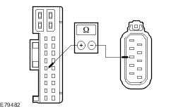
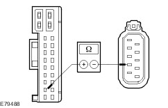
| | TEST CONDITIONS | DETAILS/RESULTS/ACTIONS | | D1: CHECK FOR SHORT TO VOLTAGE BETWEEN THE LEFT-HAND DOOR MODULE AND THE LEFT-HAND DOOR LOCK | | | 1 Disconnect Connector C5PL01-A from the left-hand door module. | | | 2 Disconnect Connector C5PL63 from the left-hand door lock. | | | 3 Ignition switch in position II. | | | 4 Measure the voltage between the left-hand door module, connector C5PL01-A, pin 7, circuit CPL51A (BK)(RHD vehicles: circuit CPL51AA (BK)), wiring harness side and ground. | | | Is a voltage measured? Yes LOCATE and REPAIR the short to voltage in the circuit between the left-hand door module and the left-hand door lock with the aid of the Wiring Diagrams. CHECK the operation of the system. No | | D2: CHECK FOR A BREAK IN THE CIRCUIT BETWEEN THE LEFT-HAND DOOR MODULE AND THE LEFT-HAND DOOR LOCK | | | 1 Ignition switch in position 0. | | | 2 Measure resistance between left-hand door module, connector C5PL01-A, pin 7, circuit CPL51AA (BK), wiring harness side and left-hand door lock, connector C5PL63, pin 7, circuit CPL51AA (BK), wiring harness side. | | | Is a resistance of less than 2 Ohm measured? Yes No LOCATE and REPAIR the break in circuit CPL51AA (BK) between the left-hand door module and the left-hand door lock with the aid of the Wiring Diagrams. CHECK the operation of the system. | | D3: CHECK FOR A BREAK IN THE CIRCUIT BETWEEN THE LEFT-HAND DOOR MODULE AND THE LEFT-HAND DOOR LOCK | | | 1 Ignition switch in position 0. | | | 2 Measure the resistance between the left-hand door module, connector C5PL01-A, pin 7, circuit CPL51A (BK), wiring harness side and the left-hand door lock, connector C5PL63, pin 5, circuit CPL51A (BK), wiring harness side. | | | Is a resistance of less than 2 Ohm measured? Yes No LOCATE and REPAIR the break in circuit CPL51A (BK) between the left-hand door module and the left-hand door lock with the aid of the Wiring Diagrams. CHECK the operation of the system. | | D4: CHECK FOR SHORT TO GROUND BETWEEN THE LEFT-HAND DOOR MODULE AND THE LEFT-HAND DOOR LOCK | | | 1 Ignition switch in position 0. | | | 2 Measure the resistance between the left-hand door module, connector C5PL01-A, pin 7, circuit CPL51A (BK)(RHD vehicles: circuit CPL51AA (BK)), wiring harness side and ground. | | | Is a resistance of more than 10,000 ohms measured? Yes No LOCATE and REPAIR the short to ground in the circuit between the left-hand door module and the left-hand door lock with the aid of the Wiring Diagrams. CHECK the operation of the system. | | D5: CHECK THE VOLTAGE AT THE LEFT-HAND DOOR LOCK | | | 1 Connect Connector C5PL01-A from the left-hand door module. | | | 2 Measure voltage between left-hand door lock, connector C5PL63, pin 7, circuit CPL51AA (BK), wiring harness side and ground. | | | 3 Lock and unlock the vehicle with the key in the right-hand lock cylinder. | | | Is battery voltage measured during unlocking? Yes No CHECK and if necessary RENEW the left-hand door module. CHECK the operation of the system. | | D6: CHECK THE VOLTAGE AT THE LEFT-HAND DOOR LOCK | | | 1 Measure the voltage between the left-hand door lock, connector C6PL63, pin 7, circuit CPL51AA (BK), wiring harness side and ground. | | | 2 Double lock and unlock the vehicle with the key in the right-hand lock cylinder. | | | Is battery voltage measured during unlocking? Yes CHECK and if necessary RENEW the left-hand door lock. CHECK the operation of the system. No CHECK and if necessary RENEW the left-hand door module. CHECK the operation of the system. | | D7: CHECK THE VOLTAGE AT THE LEFT-HAND DOOR MODULE | | | 1 Connect Connector C5PL01-A from the left-hand door module. | | | 2 Measure voltage between left-hand door lock, connector C5PL63, pin 5, circuit CPL51A (BK), wiring harness side and ground. | | | 3 Lock and unlock the vehicle with the key in the right-hand lock cylinder. | | | Is battery voltage measured during unlocking? Yes No CHECK and if necessary RENEW the left-hand door module. CHECK the operation of the system. | | D8: CHECK THE VOLTAGE AT THE LEFT-HAND DOOR LOCK | | | 1 Measure voltage between left-hand door lock, connector C5PL63, pin 5, circuit CPL51A (BK), wiring harness side and ground. | | | 2 Double lock and unlock the vehicle with the key in the right-hand lock cylinder. | | | Is battery voltage measured during unlocking? Yes CHECK and if necessary RENEW the left-hand door lock. CHECK the operation of the system. No CHECK and if necessary RENEW the left-hand door module. CHECK the operation of the system. | | PINPOINT TEST E : CIRCUIT OF THE LEFT-HAND CENTRAL LOCKING MOTOR WITH DOUBLE LOCKING FAULTY. | WARNING:The window anti-trap function will not operate during the window motor initialization procedure. | NOTE:If the power to a window regulator motor has been disconnected, it is necessary to initialize that window regulator motor.
REFER to: Fensterhebermotor initialisieren (501-11, General Procedures).
| | TEST CONDITIONS | DETAILS/RESULTS/ACTIONS | | E1: CHECK FOR SHORT TO VOLTAGE BETWEEN THE LEFT-HAND DOOR MODULE AND THE LEFT-HAND DOOR LOCK | | | 1 Disconnect Connector C5PL01-A from the left-hand door module. | | | 2 Disconnect Connector C5PL63 from the left-hand door lock. | | | 3 Ignition switch in position II. | | | 4 Measure the voltage between the left-hand door module, connector C5PL01-A, pin 10, circuit CPL02A (BK)(RHD vehicles: circuit CPL02AA (BK)), wiring harness side and ground. | | | Is a voltage measured? Yes LOCATE and REPAIR the short to voltage in the circuit between the left-hand door module and the left-hand door lock with the aid of the Wiring Diagrams. CHECK the operation of the system. No | | E2: CHECK FOR A BREAK IN THE CIRCUIT BETWEEN THE LEFT-HAND DOOR MODULE AND THE LEFT-HAND DOOR LOCK | | | 1 Ignition switch in position 0. | | | 2 Measure resistance between left-hand door module, connector C5PL01-A, pin 10, circuit CPL02A (BK), wiring harness side and left-hand door lock, connector C5PL63, pin 7, circuit CPL02A (BK), wiring harness side. | | | Is a resistance of less than 2 Ohm measured? Yes No LOCATE and REPAIR the break in circuit CPL02A (BK) between the left-hand door module and the left-hand door lock with the aid of the Wiring Diagrams. CHECK the operation of the system. | | E3: CHECK FOR A BREAK IN THE CIRCUIT BETWEEN THE LEFT-HAND DOOR MODULE AND THE LEFT-HAND DOOR LOCK | | | 1 Ignition switch in position 0. | | | 2 Measure resistance between left-hand door module, connector C5PL01-A, pin 10, circuit CPL02AA (BK), wiring harness side and left-hand door lock, connector C5PL63, pin 5, circuit CPL02AA (BK), wiring harness side. | | | Is a resistance of less than 2 Ohm measured? Yes No LOCATE and REPAIR the break in circuit CPL02AA (BK) between the left-hand door module and the left-hand door lock with the aid of the Wiring Diagrams. CHECK the operation of the system. | | E4: CHECK FOR SHORT TO GROUND BETWEEN THE LEFT-HAND DOOR MODULE AND THE LEFT-HAND DOOR LOCK | | | 1 Measure the resistance between the left-hand door module, connector C5PL01-A, pin 10, circuit CPL02A (BK)(RHD vehicles: circuit CPL02AA (BK)), wiring harness side and ground. | | | Is a resistance of more than 10,000 ohms measured? Yes No LOCATE and REPAIR the short to ground in the circuit between the left-hand door module and the left-hand door lock with the aid of the Wiring Diagrams. CHECK the operation of the system. | | E5: CHECK THE VOLTAGE AT THE LEFT-HAND DOOR LOCK | | | 1 Connect Connector C5PL01-A from the left-hand door module. | | | 2 Measure voltage between left-hand door lock, connector C5PL63, pin 7, circuit CPL02A (BK), wiring harness side and ground. | | | 3 Lock and unlock the vehicle with the key in the right-hand lock cylinder. | | | Is battery voltage measured during unlocking? Yes No CHECK and if necessary RENEW the left-hand door module. CHECK the operation of the system. | | E6: CHECK THE VOLTAGE AT THE LEFT-HAND DOOR LOCK | | | 1 Measure voltage between left-hand door lock, connector C6PL63, pin 7, circuit CPL02A (BK), wiring harness side and ground. | | | 2 Double lock and unlock the vehicle with the key in the right-hand lock cylinder. | | | Is battery voltage measured during unlocking? Yes CHECK and if necessary RENEW the left-hand door lock. CHECK the operation of the system. No CHECK and if necessary RENEW the left-hand door module. CHECK the operation of the system. | | E7: CHECK THE VOLTAGE AT THE LEFT-HAND DOOR MODULE | | | 1 Connect Connector C5PL01-A from the left-hand door module. | | | 2 Measure the voltage between the left-hand door lock, connector C5PL63, pin 5, circuit CPL02AA (BK), wiring harness side and ground. | | | 3 Lock and unlock the vehicle with the key in the right-hand lock cylinder. | | | Is battery voltage measured during unlocking? Yes No CHECK and if necessary RENEW the left-hand door module. CHECK the operation of the system. | | E8: CHECK THE VOLTAGE AT THE LEFT-HAND DOOR LOCK | | | 1 Measure the voltage between the left-hand door lock, connector C5PL63, pin 5, circuit CPL02AA (BK), wiring harness side and ground. | | | 2 Double lock and unlock the vehicle with the key in the right-hand lock cylinder. | | | Is battery voltage measured during unlocking? Yes CHECK and if necessary RENEW the left-hand door lock. CHECK the operation of the system. No CHECK and if necessary RENEW the left-hand door module. CHECK the operation of the system. | | PINPOINT TEST F : CIRCUIT OF THE RIGHT-HAND CENTRAL LOCKING MOTOR WITH DOUBLE LOCKING FAULTY. | WARNING:The window anti-trap function will not operate during the window motor initialization procedure. | NOTE:If the power to a window regulator motor has been disconnected, it is necessary to initialize that window regulator motor.
REFER to: Fensterhebermotor initialisieren (501-11, General Procedures).
| | TEST CONDITIONS | DETAILS/RESULTS/ACTIONS | | F1: CHECK FOR SHORT TO VOLTAGE BETWEEN THE RIGHT-HAND DOOR MODULE AND THE RIGHT-HAND DOOR LOCK | | | 1 Disconnect Connector C6PL01-A from the right-hand door module. | | | 2 Disconnect Connector C6PL64 from the right-hand door lock. | | | 3 Ignition switch in position II. | | | 4 Measure the voltage between the right-hand door module, connector C6PL01-A, pin 10, circuit CPL65A (BK)(RHD vehicles: circuit CPL65AA (BK)), wiring harness side and ground. | | | Is a voltage measured? Yes LOCATE and REPAIR the short to voltage in the circuit between the right-hand door module and the right-hand door lock with the aid of the Wiring Diagrams. CHECK the operation of the system. No | | F2: CHECK FOR A BREAK IN THE CIRCUIT BETWEEN THE RIGHT-HAND DOOR MODULE AND THE RIGHT-HAND DOOR LOCK | | | 1 Ignition switch in position 0. | | | 2 Measure the resistance between the right-hand door module, connector C6PL01-A, pin 10, circuit CPL65A (BK), wiring harness side and the right-hand door lock, connector C6PL64, pin 5, circuit CPL65A (BK), wiring harness side. | | | Is a resistance of less than 2 Ohm measured? Yes No LOCATE and REPAIR the break in circuit CPL65A (BK) between the right-hand door module and the right-hand door lock with the aid of the Wiring Diagrams. CHECK the operation of the system. | | F3: CHECK FOR A BREAK IN THE CIRCUIT BETWEEN THE RIGHT-HAND DOOR MODULE AND THE RIGHT-HAND DOOR LOCK | | | 1 Ignition switch in position 0. | | | 2 Measure the resistance between the right-hand door module, connector C6PL01-A, pin 10, circuit CPL65AA (BK), wiring harness side and the right-hand door lock, connector C6PL64, pin 7, circuit CPL65AA (BK), wiring harness side. | | | Is a resistance of less than 2 Ohm measured? Yes No LOCATE and REPAIR the break in circuit CPL65AA (BK) between the right-hand door module and the right-hand door lock with the aid of the Wiring Diagrams. CHECK the operation of the system. | | F4: CHECK FOR SHORT TO GROUND BETWEEN THE RIGHT-HAND DOOR MODULE AND THE RIGHT-HAND DOOR LOCK | | | 1 Ignition switch in position 0. | | | 2 Measure the resistance between the right-hand door module, connector C6PL01-A, pin 10, circuit CPL65A (BK)(RHD vehicles: circuit CPL65AA (BK)), wiring harness side and ground. | | | Is a resistance of more than 10,000 ohms measured? Yes No LOCATE and REPAIR the short to ground in the circuit between the right-hand door module and the right-hand door lock with the aid of the Wiring Diagrams. CHECK the operation of the system. | | F5: CHECK THE VOLTAGE AT THE RIGHT-HAND DOOR LOCK | | | 1 Connect Connector C6PL01-A from the right-hand door module. | | | 2 Measure the voltage between the right-hand door lock, connector C6PL64, pin 5, circuit CPL65A (BK), wiring harness side and ground. | | | 3 Lock and unlock the vehicle with the key in the left-hand lock cylinder. | | | Is battery voltage measured during unlocking? Yes No CHECK and if necessary RENEW the right-hand door module. CHECK the operation of the system. | | F6: CHECK THE VOLTAGE AT THE RIGHT-HAND DOOR LOCK | | | 1 Measure the voltage between the right-hand door lock, connector C6PL64, pin 5, circuit CPL65A (BK), wiring harness side and ground. | | | 2 Double lock and unlock the vehicle with the key in the left-hand lock cylinder. | | | Is battery voltage measured during unlocking? Yes CHECK and if necessary RENEW the right-hand door lock. CHECK the operation of the system. No CHECK and if necessary RENEW the right-hand door module. CHECK the operation of the system. | | F7: CHECK THE VOLTAGE AT THE RIGHT-HAND DOOR LOCK | | | 1 Connect Connector C6PL01-A from the right-hand door module. | | | 2 Measure the voltage between the right-hand door lock, connector C6PL64, pin 7, circuit CPL66A (BK), wiring harness side and ground. | | | 3 Double lock and unlock the vehicle with the key in the left-hand lock cylinder. | | | Is battery voltage measured during unlocking? Yes No CHECK and if necessary RENEW the right-hand door module. CHECK the operation of the system. | | F8: CHECK THE VOLTAGE AT THE RIGHT-HAND DOOR MODULE | | | 1 Measure the voltage between the right-hand door lock, connector C6PL64, pin 7, circuit CPL66A (BK), wiring harness side and ground. | | | 2 Lock and unlock the vehicle with the key in the left-hand lock cylinder. | | | Is battery voltage measured during unlocking? Yes CHECK and if necessary RENEW the right-hand door lock. CHECK the operation of the system. No CHECK and if necessary RENEW the right-hand door module. CHECK the operation of the system. | | PINPOINT TEST G : CIRCUIT OF THE REAR RIGHT-HAND CENTRAL LOCKING MOTOR FAULTY. | WARNING:The window anti-trap function will not operate during the window motor initialization procedure. | NOTE:If the power to a window regulator motor has been disconnected, it is necessary to initialize that window regulator motor.
REFER to: Fensterhebermotor initialisieren (501-11, General Procedures).
| | TEST CONDITIONS | DETAILS/RESULTS/ACTIONS | | G1: CHECK FOR SHORT TO VOLTAGE BETWEEN THE REAR RIGHT-HAND DOOR MODULE AND THE REAR RIGHT-HAND DOOR LOCK | | | 1 Disconnect Connector C8PL01 from the rear right-hand door module. | | | 2 Disconnect Connector C8PL72 from the rear right-hand door lock. | | | 3 Ignition switch in position II. | | | 4 Measure voltage between rear right-hand door module, connector C8PL01, pin 10, circuit CPL11A (BK), wiring harness side and ground. | | | Is a voltage measured? Yes LOCATE and REPAIR the short to voltage in circuit CPL11A (BK) between the right-hand rear door module and the right-hand rear door lock with the aid of the Wiring Diagrams. CHECK the operation of the system. No | | G2: CHECK FOR A BREAK IN THE CIRCUIT BETWEEN THE RIGHT-HAND REAR DOOR MODULE AND THE RIGHT-HAND REAR DOOR LOCK | | | 1 Ignition switch in position 0. | | | 2 Measure the resistance between the right-hand rear door module, connector C8PL01, pin 10, circuit CPL11A (BK), wiring harness side and the right-hand rear door lock, connector C8PL72, pin 5, circuit CPL11A (BK), wiring harness side. | | | Is a resistance of less than 2 Ohm measured? Yes No LOCATE and REPAIR the break in circuit CPL11A (BK) between the right-hand rear door module and the right-hand rear door lock with the aid of the Wiring Diagrams. CHECK the operation of the system. | | G3: CHECK FOR SHORT TO GROUND IN THE CIRCUIT BETWEEN THE REAR RIGHT-HAND DOOR MODULE AND THE REAR RIGHT-HAND DOOR LOCK | | | 1 Ignition switch in position 0. | | | 2 Measure the resistance between the right-hand rear door module, connector C8PL01, pin 10, circuit CPL11A (BK), wiring harness side and ground. | | | Is a resistance of more than 10,000 ohms measured? Yes No LOCATE and REPAIR the short to ground in circuit CPL11A (BK) between the right-hand rear door module and the right-hand rear door lock with the aid of the Wiring Diagrams. CHECK the operation of the system. | | G4: CHECK THE VOLTAGE AT THE RIGHT-HAND REAR DOOR MODULE | | | 1 Connect Connector C8PL01 from the rear right-hand door module. | | | 2 Measure the voltage between the rear right-hand door lock, connector C8PL72, pin 5, circuit CPL11A (BK), wiring harness side and ground. | | | 3 Lock and unlock the vehicle with the key in the left-hand lock cylinder. | | | Is battery voltage measured during unlocking? Yes No CHECK and if necessary RENEW the right-hand rear door module. CHECK the operation of the system. | | G5: CHECK THE VOLTAGE AT THE RIGHT-HAND REAR DOOR LOCK | | | 1 Measure the voltage between the rear right-hand door lock, connector C8PL72, pin 5, circuit CPL11A (BK), wiring harness side and ground. | | | 2 Double lock and unlock the vehicle with the key in the left-hand lock cylinder. | | | Is battery voltage measured during unlocking? Yes CHECK and if necessary RENEW the right-hand rear door lock. CHECK the operation of the system. No CHECK and if necessary RENEW the right-hand rear door module. CHECK the operation of the system. | | PINPOINT TEST H : CIRCUIT OF THE LEFT-HAND REAR CENTRAL LOCKING MOTOR FAULTY. | WARNING:The window anti-trap function will not operate during the window motor initialization procedure. | NOTE:If the power to a window regulator motor has been disconnected, it is necessary to initialize that window regulator motor.
REFER to: Fensterhebermotor initialisieren (501-11, General Procedures).
| | TEST CONDITIONS | DETAILS/RESULTS/ACTIONS | | H1: CHECK FOR SHORT TO VOLTAGE BETWEEN THE LEFT-HAND REAR DOOR MODULE AND THE LEFT-HAND REAR DOOR LOCK | | | 1 Disconnect Connector C7PL01 from the left-hand rear door module. | | | 2 Disconnect Connector C7PL71 from the left-hand rear door lock. | | | 3 Ignition switch in position II. | | | 4 Measure voltage between rear left-hand door module, connector C7PL01, pin 10, circuit CPL04A (BK), wiring harness side and ground. | | | Is a voltage measured? Yes LOCATE and REPAIR the short to voltage in circuit CPL04A (BK) between the left-hand rear door module and the left-hand door lock with the aid of the Wiring Diagrams. CHECK the operation of the system. No | | H2: CHECK FOR A BREAK IN THE CIRCUIT BETWEEN THE LEFT-HAND REAR DOOR MODULE AND THE LEFT-HAND REAR DOOR LOCK | | | 1 Ignition switch in position 0. | | | 2 Measure resistance between rear left-hand door module, connector C7PL01, pin 10, circuit CPL04A (BK), wiring harness side and rear left-hand door lock, connector C7PL71, pin 7, circuit CPL04A (BK), wiring harness side. | | | Is a resistance of less than 2 Ohm measured? Yes No LOCATE and REPAIR the break in circuit CPL04A (BK) between the left-hand rear door module and the left-hand rear door lock with the aid of the Wiring Diagrams. CHECK the operation of the system. | | H3: CHECK FOR SHORT TO GROUND BETWEEN THE LEFT-HAND REAR DOOR MODULE AND THE LEFT-HAND REAR DOOR LOCK | | | 1 Ignition switch in position 0. | | | 2 Measure the resistance between the left-hand rear door module, connector C7PL01, pin 10, circuit CPL04A (BK), wiring harness side and ground. | | | Is a resistance of more than 10,000 ohms measured? Yes No LOCATE and REPAIR the short to ground in circuit CPL04A (BK) between the left-hand rear door module and the left-hand rear door lock with the aid of the Wiring Diagrams. CHECK the operation of the system. | | H4: CHECK THE VOLTAGE AT THE LEFT-HAND REAR DOOR LOCK | | | 1 Connect Connector C7PL01 from the left-hand rear door module. | | | 2 Measure voltage between rear left-hand door lock, connector C7PL71, pin 7, circuit CPL04A (BK), wiring harness side and ground. | | | 3 Lock and unlock the vehicle with the key in the left-hand lock cylinder. | | | Is battery voltage measured during unlocking? Yes No CHECK and if necessary RENEW the left-hand rear door module. CHECK the operation of the system. | | H5: CHECK THE VOLTAGE AT THE LEFT-HAND REAR DOOR LOCK | | | 1 Measure voltage between rear left-hand door lock, connector C7PL71, pin 7, circuit CPL04A (BK), wiring harness side and ground. | | | 2 Double lock and unlock the vehicle with the key in the left-hand lock cylinder. | | | Is battery voltage measured during unlocking? Yes CHECK and if necessary RENEW the left-hand rear door lock. CHECK the operation of the system. No CHECK and if necessary RENEW the left-hand rear door lock. CHECK the operation of the system. | | PINPOINT TEST I : CIRCUIT OF THE DRIVER'S SIDE LEFT-HAND REAR CENTRAL LOCKING MOTOR WITH DOUBLE LOCKING FAULTY. | WARNING:The window anti-trap function will not operate during the window motor initialization procedure. | NOTE:If the power to a window regulator motor has been disconnected, it is necessary to initialize that window regulator motor.
REFER to: Fensterhebermotor initialisieren (501-11, General Procedures).
| | TEST CONDITIONS | DETAILS/RESULTS/ACTIONS | | I1: CHECK FOR SHORT TO VOLTAGE BETWEEN THE LEFT-HAND REAR DOOR MODULE AND THE LEFT-HAND REAR DOOR LOCK | | | 1 Disconnect Connector C7PL01 from the left-hand rear door module. | | | 2 Disconnect Connector C7PL71 from the left-hand rear door lock. | | | 3 Ignition switch in position II. | | | 4 Measure voltage between rear left-hand door module, connector C7PL01, pin 9, circuit CPL08A (BK), wiring harness side and ground. | | | Is a voltage measured? Yes LOCATE and REPAIR the short to voltage in circuit CPL08A (BK) between the left-hand rear door module and the left-hand door lock with the aid of the Wiring Diagrams. CHECK the operation of the system. No | | I2: CHECK FOR A BREAK IN THE CIRCUIT BETWEEN THE LEFT-HAND REAR DOOR MODULE AND THE LEFT-HAND REAR DOOR LOCK | | | 1 Ignition switch in position 0. | | | 2 Measure resistance between rear left-hand door module, connector C7PL01, pin 9, circuit CPL08A (BK), wiring harness side and rear left-hand door lock, connector C7PL71, pin 6, circuit CPL08A (BK), wiring harness side. | | | Is a resistance of less than 2 Ohm measured? Yes No LOCATE and REPAIR the break in circuit CPL08A (BK) between the left-hand rear door module and the left-hand rear door lock with the aid of the Wiring Diagrams. CHECK the operation of the system. | | I3: CHECK FOR SHORT TO GROUND BETWEEN THE LEFT-HAND REAR DOOR MODULE AND THE LEFT-HAND REAR DOOR LOCK | | | 1 Ignition switch in position 0. | | | 2 Measure the resistance between the left-hand rear door module, connector C7PL01, pin 9, circuit CPL08A (BK), wiring harness side and ground. | | | Is a resistance of more than 10,000 ohms measured? Yes No LOCATE and REPAIR the short to ground in circuit CPL08A (BK) between the left-hand rear door module and the left-hand rear door lock with the aid of the Wiring Diagrams. CHECK the operation of the system. | | I4: CHECK THE VOLTAGE AT THE LEFT-HAND REAR DOOR LOCK | | | 1 Connect Connector C7PL01 from the left-hand rear door module. | | | 2 Measure voltage between rear left-hand door lock, connector C7PL71, pin 6, circuit CPL08A (BK), wiring harness side and ground. | | | 3 Lock and unlock the vehicle with the key in the left-hand lock cylinder. | | | Is battery voltage measured during unlocking? Yes No CHECK and if necessary RENEW the left-hand rear door module. CHECK the operation of the system. | | I5: CHECK THE VOLTAGE AT THE LEFT-HAND REAR DOOR LOCK | | | 1 Measure voltage between rear left-hand door lock, connector C7PL71, pin 6, circuit CPL08A (BK), wiring harness side and ground. | | | 2 Double lock and unlock the vehicle with the key in the left-hand lock cylinder. | | | Is battery voltage measured during unlocking? Yes CHECK and if necessary RENEW the left-hand rear door lock. CHECK the operation of the system. No CHECK and if necessary RENEW the left-hand rear door lock. CHECK the operation of the system. | | PINPOINT TEST J : CIRCUIT OF THE RIGHT-HAND REAR CENTRAL LOCKING MOTOR WITH DOUBLE LOCKING FAULTY. | WARNING:The window anti-trap function will not operate during the window motor initialization procedure. | NOTE:If the power to a window regulator motor has been disconnected, it is necessary to initialize that window regulator motor.
REFER to: Fensterhebermotor initialisieren (501-11, General Procedures).
| | TEST CONDITIONS | DETAILS/RESULTS/ACTIONS | | J1: CHECK FOR SHORT TO VOLTAGE BETWEEN THE REAR RIGHT-HAND DOOR MODULE AND THE REAR RIGHT-HAND DOOR LOCK | | | 1 Disconnect Connector C8PL01 from the rear right-hand door module. | | | 2 Disconnect Connector C8PL72 from the rear right-hand door lock. | | | 3 Ignition switch in position II. | | | 4 Measure voltage between rear right-hand door module, connector C8PL01, pin 9, circuit CPL12A (BK), wiring harness side and ground. | | | Is a voltage measured? Yes LOCATE and REPAIR the short to voltage in circuit CPL12A (BK) between the right-hand rear door module and the right-hand rear door lock with the aid of the Wiring Diagrams. CHECK the operation of the system. No | | J2: CHECK FOR A BREAK IN THE CIRCUIT BETWEEN THE RIGHT-HAND REAR DOOR MODULE AND THE RIGHT-HAND REAR DOOR LOCK | | | 1 Ignition switch in position 0. | | | 2 Measure resistance between rear right-hand door module, connector C8PL01, pin 9, circuit CPL12A (BK), wiring harness side and rear right-hand door lock, connector C8PL72, pin 6, circuit CPL12A (BK), wiring harness side. | | | Is a resistance of less than 2 Ohm measured? Yes No LOCATE and REPAIR the break in circuit CPL12A (BK) between the right-hand rear door module and the right-hand rear door lock with the aid of the Wiring Diagrams. CHECK the operation of the system. | | J3: CHECK FOR SHORT TO GROUND IN THE CIRCUIT BETWEEN THE REAR RIGHT-HAND DOOR MODULE AND THE REAR RIGHT-HAND DOOR LOCK | | | 1 Ignition switch in position 0. | | | 2 Measure the resistance between the right-hand rear door module, connector C8PL01, pin 9, circuit CPL12A (BK), wiring harness side and ground. | | | Is a resistance of more than 10,000 ohms measured? Yes No LOCATE and REPAIR the short to ground in circuit CPL12A (BK) between the right-hand rear door module and the right-hand rear door lock with the aid of the Wiring Diagrams. CHECK the operation of the system. | | J4: CHECK THE VOLTAGE AT THE RIGHT-HAND REAR DOOR LOCK | | | 1 Connect Connector C8PL01 from the rear right-hand door module. | | | 2 Measure the voltage between the right-hand rear door lock, connector C8PL72, pin 6, circuit CPL12A (BK), wiring harness side and ground. | | | 3 Lock and unlock the vehicle with the key in the left-hand lock cylinder. | | | Is battery voltage measured during unlocking? Yes No CHECK and if necessary RENEW the right-hand rear door module. CHECK the operation of the system. | | J5: CHECK THE VOLTAGE AT THE RIGHT-HAND REAR DOOR LOCK | | | 1 Measure the voltage between the right-hand rear door lock, connector C8PL72, pin 6, circuit CPL12A (BK), wiring harness side and ground. | | | 2 Double lock and unlock the vehicle with the key in the left-hand lock cylinder. | | | Is battery voltage measured during unlocking? Yes CHECK and if necessary RENEW the right-hand rear door lock. CHECK the operation of the system. No CHECK and if necessary RENEW the right-hand rear door lock. CHECK the operation of the system. | | PINPOINT TEST K : CIRCUIT OF THE PASSENGER COMPARTMENT LOCKING SWITCH FAULTY. | WARNING:The window anti-trap function will not operate during the window motor initialization procedure. | NOTE:If the power to a window regulator motor has been disconnected, it is necessary to initialize that window regulator motor.
REFER to: Fensterhebermotor initialisieren (501-11, General Procedures).
| | TEST CONDITIONS | DETAILS/RESULTS/ACTIONS | | K1: CHECK FOR A BREAK IN THE CIRCUIT BETWEEN THE FRONT DOOR MODULE AND THE FRONT DOOR LOCK | | | 1 Ignition switch in position 0. | | | 2 Disconnect Connector C5PL01-B from the front door module. | | | 3 Disconnect Connector C5PL63 from the front door lock. | | | 4 Measure the resistance between the front door module, connector C5PL01-B, pin 21, circuit CPL42A (BK), wiring harness side and the front door lock, connector C5PL63, pin 2, circuit CPL42A (BK), wiring harness side. | | | Is a resistance of less than 2 Ohm measured? Yes No LOCATE and REPAIR the break in circuit CPL42A (BK) between the front door module and the front door lock with the aid of the Wiring Diagrams. CHECK the operation of the system. | | K2: CHECK FOR A BREAK IN THE CIRCUIT BETWEEN THE FRONT DOOR MODULE AND THE FRONT DOOR LOCK | | | 1 Measure resistance between front door module, connector C5PL01-B, pin 5, circuit CPL43A (BK), wiring harness side and front door lock, connector C5PL63, pin 3, circuit CPL43A (BK), wiring harness side. | | | Is a resistance of less than 2 Ohm measured? Yes No LOCATE and REPAIR the break in circuit CPL43A (BK) between the front door module and the front door lock with the aid of the Wiring Diagrams. CHECK the operation of the system. | | K3: CHECK FOR SHORT TO VOLTAGE BETWEEN THE FRONT DOOR MODULE AND THE FRONT DOOR LOCK | | | 1 Ignition switch in position II. | | | 2 Measure the voltage between the front door module, connector C5PL01-B, pin 21, circuit CPL42A (BK), wiring harness side and ground. | | | Is a voltage measured? Yes LOCATE and REPAIR the short to voltage in circuit CPL42A (BK) between the front door module and the front door lock with the aid of the Wiring Diagrams. CHECK the operation of the system. No | | K4: CHECK FOR SHORT TO VOLTAGE BETWEEN THE FRONT DOOR MODULE AND THE FRONT DOOR LOCK | | | 1 Measure voltage between front door module, connector C5PL01-B, pin 5, circuit CPL43A (BK), wiring harness side and ground. | | | Is a voltage measured? Yes LOCATE and REPAIR the short to voltage in circuit CPL43A (BK) between the front door module and the front door lock with the aid of the Wiring Diagrams. CHECK the operation of the system. No | | K5: CHECK FOR SHORT TO GROUND BETWEEN THE FRONT DOOR MODULE AND THE FRONT DOOR LOCK | | | 1 Ignition switch in position 0. | | | 2 Measure the resistance between the front door module, connector C5PL01-B, pin 21, circuit CPL42A (BK), wiring harness side and ground. | | | Is a resistance of more than 10,000 ohms measured? Yes No LOCATE and REPAIR the short to ground in circuit CPL42A (BK) between the front door module and the front door lock with the aid of the Wiring Diagrams. CHECK the operation of the system. | | K6: CHECK FOR SHORT TO GROUND BETWEEN THE FRONT DOOR MODULE AND THE FRONT DOOR LOCK | | | 1 Measure the resistance between the front door module, connector C5PL01-B, pin 5, circuit CPL43A (BK), wiring harness side and ground. | | | Is a resistance of more than 10,000 ohms measured? Yes No LOCATE and REPAIR the short to ground in circuit CPL43A (BK) between the front door module and the front door lock with the aid of the Wiring Diagrams. CHECK the operation of the system. | | K7: CHECK THE VOLTAGE AT THE FRONT DOOR LOCK | | | 1 Connect Connector C5PL01-B from the front door module. | | | 2 Measure the voltage between the front door lock, connector C5PL63, pin 3, circuit CPL43A (BK), wiring harness side and pin 2, circuit CPL42A (BK), wiring harness side. | | | 3 Lock the vehicle using the passenger compartment locking switch. | | | Is a voltage of more than 3.5 V measured? Yes No CHECK and if necessary RENEW the front door module. CHECK the operation of the system. | | K8: CHECK THE VOLTAGE AT THE FRONT DOOR LOCK | | | 1 Measure the voltage between the front door lock, connector C5PL63, pin 3, circuit CPL43A (BK), wiring harness side and pin 2, circuit CPL42A (BK), wiring harness side. | | | 2 Unlock the vehicle using the passenger compartment locking switch. | | | Is a voltage of less than 1.5 V measured? Yes CHECK and if necessary RENEW the front door lock. CHECK the operation of the system. No CHECK and if necessary RENEW the front door module. CHECK the operation of the system. | | |