| Removal and Installation Special Tool(s) | | 205-316A Alignment Pins, Subframe | General Equipment Removal | | - Remove the following items:
-
Remove the stabilizer bar link, on both sides. Refer to: Rear Stabilizer Bar Link (204-02 Rear Suspension, Removal and Installation). -
Remove the spring, on both sides. Refer to: Spring (204-02 Rear Suspension, Removal and Installation). | | | -
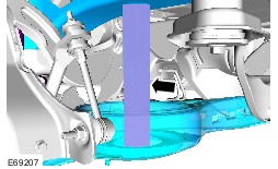
Install the spacer. Make sure that the spacer is in a vertical plane and raise the suspension to the design height setting on both sides. | | | -
NOTE:Note the position of each component before removal. | | | -
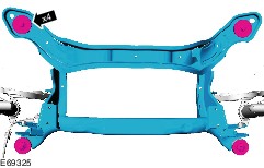
Support the rear subframe and remove the rear subframe bolts. | Installation | | -
Support the rear subframe and install the rear subframe bolts. Torque: 110 Nm | | | -
Install the spacer. Make sure that the spacer is in a vertical plane and raise the suspension to the design height setting on both sides. | | | -
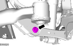
On both sides. Torque: 130 Nm | | | -
On both sides. Torque: 130 Nm | | | -
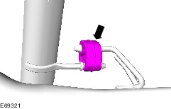
NOTE:Make sure that these components are installed to the noted removal position. Torque: 8 Nm | | | - Install the following items:
-
Install the spring, on both sides. Refer to: Spring (204-02 Rear Suspension, Removal and Installation). -
Install the stabilzer bar link, on both sides. Refer to: Rear Stabilizer Bar Link (204-02 Rear Suspension, Removal and Installation). | | | -
Check the toe setting and adjust as necessary. Refer to: Rear Toe Adjustment (204-00 Suspension System - General Information, General Procedures). Refer to: Specifications (204-00 Suspension System - General Information, Specifications). | | |