
Mustang V6-4.0L (2008)
Driver/Vehicle Information Display: Initial Inspection and Diagnostic Overview
Inspection and Verification
INSPECTION AND VERIFICATION
1. Verify the customer concern.
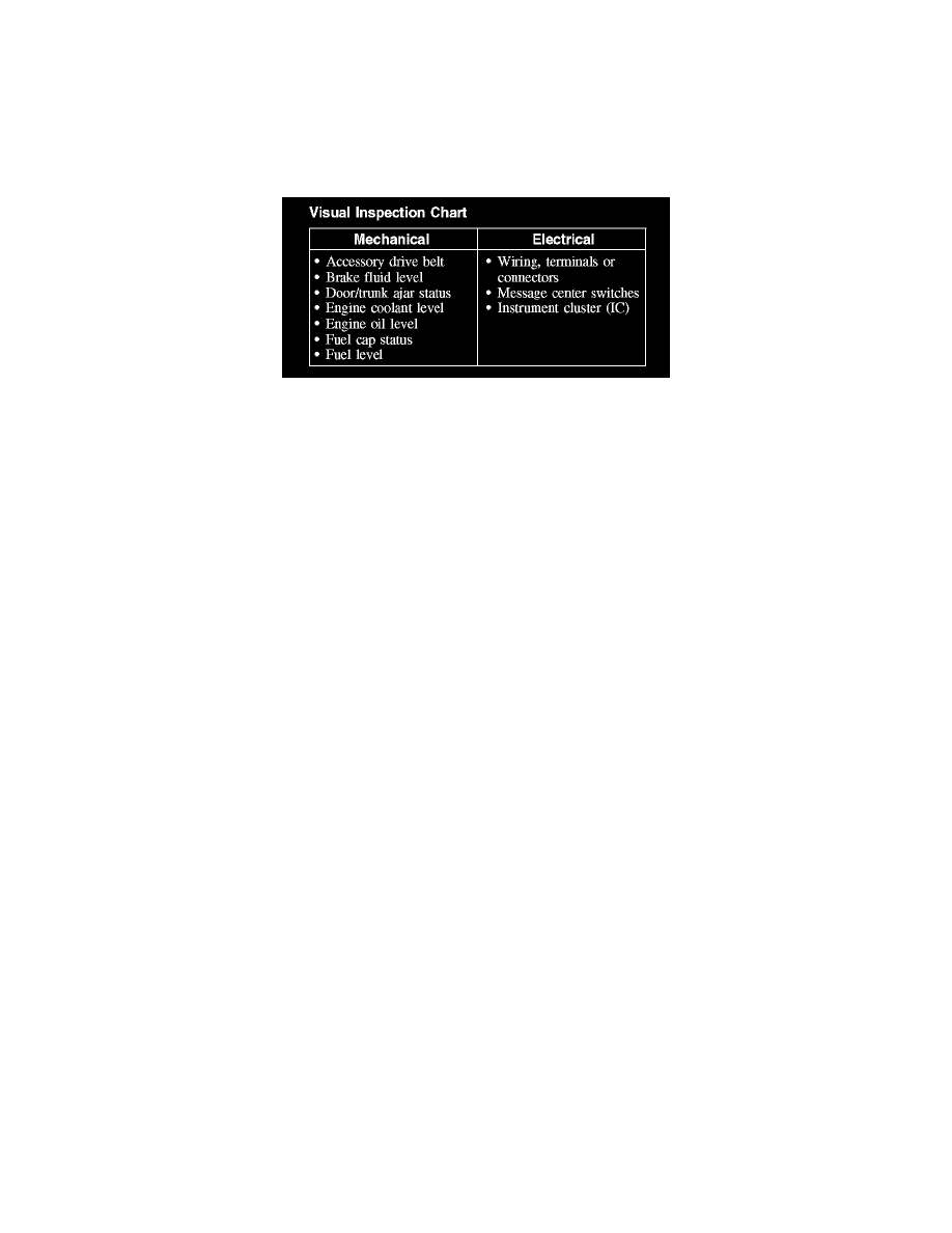
2. Visually inspect for obvious signs of mechanical or electrical damage.
Visual Inspection Chart
3. If an obvious cause for an observed or reported concern is found, correct the cause (if possible) before proceeding to the next step.
4. NOTE: Make sure to use the latest scan tool software release.
If the cause is not visually evident, connect the scan tool to the data link connector (DLC).
5. NOTE: The vehicle communication module (VCM) LED prove-out confirms power and ground from the DLC are provided to the VCM.
If the scan tool does not communicate with the VCM:
-
Check the VCM connection to the vehicle.
-
Check the scan tool connection to the VCM.
-
Refer to Information Bus (Module Communications Network), No Power To The Scan Tool, to diagnose no communication with the scan tool.
6. If the scan tool does not communicate with the vehicle:
-
Verify the ignition key is in the ON position.
-
Verify the scan tool operation with a known good vehicle.
-
Refer to Information Bus (Module Communications Network) to diagnose no response from the PCM.
7. Carry out the network test.
-
If the scan tool responds with no communication for one or more modules, refer to Information Bus (Module Communications Network).
-
If the network test passes, retrieve and record the continuous memory DTCs.
8. Clear the continuous DTCs and carry out the self-test diagnostics for the instrument cluster (IC).
9. If the DTCs retrieved are related to the concern, go to DTC Charts. See: Instrument Panel, Gauges and Warning Indicators/Testing and
Inspection/Diagnostic Trouble Code Descriptions/Information and Message Center
10. If no DTCs related to the concern are retrieved, GO to Symptom Chart. See: Symptom Related Diagnostic Procedures
Principles of Operation
PRINCIPLES OF OPERATION
The message center is a vacuum fluorescent display, which is part of the instrument cluster (IC). The message center electronic functions use both
hardwired and controller area network (CAN) circuits to transmit and receive information.
As a technician it is very important to understand:
-
where the input (command) originates from.
-
all the information (messages) necessary in order for a feature to operate.
-
which module(s) receive(s) the input or command message.
-
does the module which received the input (message) control the output of the feature, or does it output a message over the communication network
circuits to another module.
-
which module controls the output of the feature.
Instrument Cluster (IC) Network Messages
NOTE: Whenever a network message is suspected as missing, confirmed by a missing message DTC, it is important to look for other symptoms that