
Mustang V6-4.0L (2008)
Parking Lamp: Initial Inspection and Diagnostic Overview
Inspection and Verification
INSPECTION AND VERIFICATION
1. Verify the customer concern.
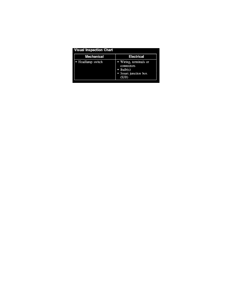
2. Visually inspect for obvious signs of mechanical or electrical damage.
Visual Inspection Chart
3. If an obvious cause for an observed or reported concern is found, correct the cause (if possible) before proceeding to the next step.
NOTE:
-
Make sure the headlamp switch is in the OFF position.
-
Make sure the multifunction switch is in the LOW BEAM position.
4. NOTE: Make sure to use the latest scan tool software release.
If the cause is not visually evident, connect the scan tool to the data link connector (DLC).
5. NOTE: The vehicle communication module (VCM) LED prove-out confirms power and ground from the DLC are provided to the VCM.
If the scan tool does not communicate with the VCM:
-
Check the VCM connection to the vehicle.
-
Check the scan tool connection to the VCM.
-
Refer to Information Bus (Module Communications Network), No Power To The Scan Tool, to diagnose no communication with the scan tool.
6. If the scan tool does not communicate with the vehicle:
-
Verify the ignition key is in the ON position.
-
Verify the scan tool operation with a known good vehicle.
-
Refer to Information Bus (Module Communications Network) to diagnose no response from the PCM.
7. Carry out the network test:
-
If the scan tool responds with no communication for one or more modules, refer to Information Bus (Module Communications Network).
-
If the network test passes, retrieve and record the continuous memory DTCs.
8. Clear the continuous DTCs and carry out the self-test diagnostics for the SJB.
9. If the DTCs retrieved are related to the concern, go to DTC Charts. For all other DTCs, refer to Body Control Systems (Multifunction Electronic
Control Module). See: Diagnostic Trouble Code Descriptions
10. If no DTCs related to the concern are retrieved, GO to Symptom Chart. See: Symptom Related Diagnostic Procedures
Principles of Operation
PRINCIPLES OF OPERATION
NOTE: The smart junction box (SJB) is also known as the generic electronic module (GEM).
When the SJB receives an input from the headlamp switch indicating a request for the parking lamps, the SJB supplies voltage to the parking lamps.
The battery saver feature does not turn the parking lamps off when the headlamp switch is in the PARKING LAMPS ON position.
The SJB monitors the headlamp switch position by sending voltage reference signals on multiple circuits to the headlamp switch. At any given time, one
of the signal circuits is routed to ground. If the SJB does not detect any of the inputs to the headlamp switch is active (routed to ground) for 5 seconds,
the SJB turns on the exterior lights and keeps them on for 10 minutes after the ignition switch is turned off (or 10 minutes from the time the SJB does
not detect any headlamp switch input if the ignition switch was already off). If the SJB detects multiple circuits short to ground, the SJB implements a
planned strategy depending on the multiple inputs received. If either of these situations occur, the SJB should NOT be ruled immediately as being at
fault. This is normal behavior of the SJB design as it has detected a fault with the inputs from the headlamp switch.