
Mustang Cobra V8-281 4.6L DOHC VIN V MFI (1997)
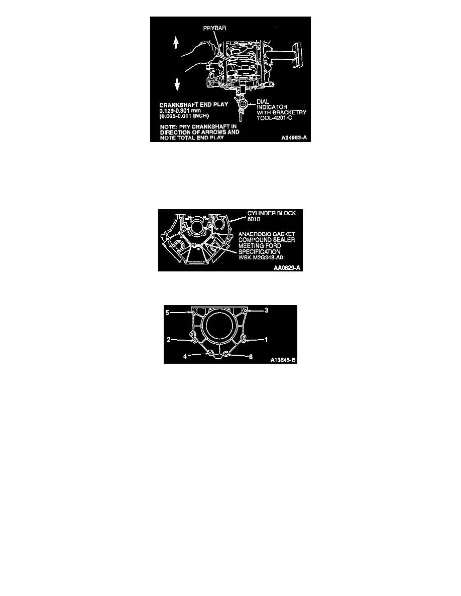
17. Check crankshaft end play in both directions as shown.
18. Remove all traces of oil, dirt and sealant from the cylinder block and retainer sealing surfaces. Sealing surfaces must be clean and dry before
applying sealant.
NOTE: Crankshaft rear oil seal retainer (6335) must be installed and the retaining bolts tightened to specification within five minutes of Sealer
application.
19. Apply a 2.0 mm (0.08 inch) continuous bead of Anaerobic Gasket Compound Sealer or equivalent meeting Ford specification WSK-M2G348-A9
to cylinder block as shown.
20. Install crankshaft rear oil seal and retainer to cylinder block and tighten six bolts in sequence to 8-12 Nm (71-106 inch lbs.) no more than four
minutes after applying sealant.
21. If removed, install crankshaft rear oil seal (6701) using Rear Crankshaft Adapter T95P-6701-DH and Rear Crankshaft Seal Replacer
T95P-6701-BH.
22. Install crankshaft oil slinger (6310) using Rear Crankshaft Slinger Replacer T95P-6701-CH.
23. Install flywheel (6375).
24. Turn crankshaft until the crank throw is at bottom of stroke. Install upper connecting rod bearing onto connecting rod. Lubricate connecting rod
bearing and crankshaft with clean engine oil.
CAUTION: Be sure not to scratch cylinder wall or crankshaft journal with connecting rod or damage to engine may occur.
25. Pull piston (6108) down until connecting rod bearing seats on crankshaft journal.
NOTE: Due to the use of a cracked connecting rod joint face surface, it is imperative that the connecting rod cap be properly aligned to the
connecting rod. The connecting rod bearing tangs should be located on the same side of the connecting rod.
26. Alternately tighten new connecting rod bolts in several passes to obtain 25-35 Nm (19-25 ft. lbs.) and rotate connecting rod bolts an additional
85-95°. After installation, rotate crankshaft to make sure of sure smooth operation.
27. Check connecting rod side clearance using Dial Indicator with Bracketry TOOL-4201-C or equivalent. Clearance should be 0.15-0.45 mm
(0.006-0.0177 inch). If side clearance is greater than maximum service limit of 0.50 mm (0.020 inch), replace connecting rods and/or crankshaft.
28. Install oil pan baffle. Tighten nuts to 20-30 Nm (15-22 ft. lbs.).
NOTE: Install new O-ring on oil pump screen cover and tube. Then start all bolts on oil pump and oil pump screen cover and tube before
tightening.