
Mustang Cobra V8-281 4.6L DOHC VIN V MFI (1997)
to avoid scratches and dents on cylinder head face sealing surfaces.
45. Remove rocker arms from intake valves (6507) and exhaust valves (6505) on cylinder heads.
46. Remove timing chains.
47. Rotate crankshaft counterclockwise 45° before top dead center (TDC). This will position all pistons (6108) below top of block deck face.
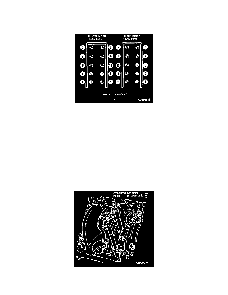
48. Using bolt removal sequence, loosen and remove 10 cylinder heads to cylinder block retaining bolts on cylinder head to be removed. Repeat
process on opposite side if both cylinder heads are to be removed. Remove cylinder heads.
49. Discard all cylinder head bolts removed.
50. Remove head casket (6051) and discard.
51. If cylinder head is to be replaced and/or serviced, refer to Cylinder Head for disassembly and assembly. See: Cylinder Head Assembly/Service and
Repair/Disassembly and Assembly
52. Remove 12 oil pan retaining bolts. Remove oil pan and oil pan gasket (6710).
53. Remove three oil pump screen cover and tube retaining bolts. Remove oil pump screen cover and tube (6622) and oil pump inlet tube gasket
(6626).
54. Remove oil pump screen cover and tube spacer from main bearing cap stud.
NOTE:
^
Pistons, connecting rods (6200) and connecting rod bearings (6211) should be numbered to make sure they are assembled in their original
positions.
^
Before removing pistons, inspect the top of the cylinder bores. If necessary, remove the ridge and/or carbon deposits from each cylinder using
Cylinder Ridge Reamer T64L-6011-EA following manufacturer's instructions.
55. Turn crankshaft until piston to be removed is at the high point of its travel.
56. If more than one piston is being removed, identify the pistons, connecting rods and connecting rod caps for cylinder position.
57. Remove the connecting rod cap and lower connecting rod bearing. Keep cap and lower connecting rod bearing together. Using Connecting Rod
Guides T93P-6136-A inserted into the bottom of connecting rod bolt holes, push the piston, connecting rod and upper connecting rod bearing
through the top of the cylinder bore. Use care to prevent damage to the crankshaft bearing and cylinder bore surfaces. Keep upper bearing and