
Probe V6-153 2.5L DOHC (1994)
Diagnostic Connector - ABS: Diagrams
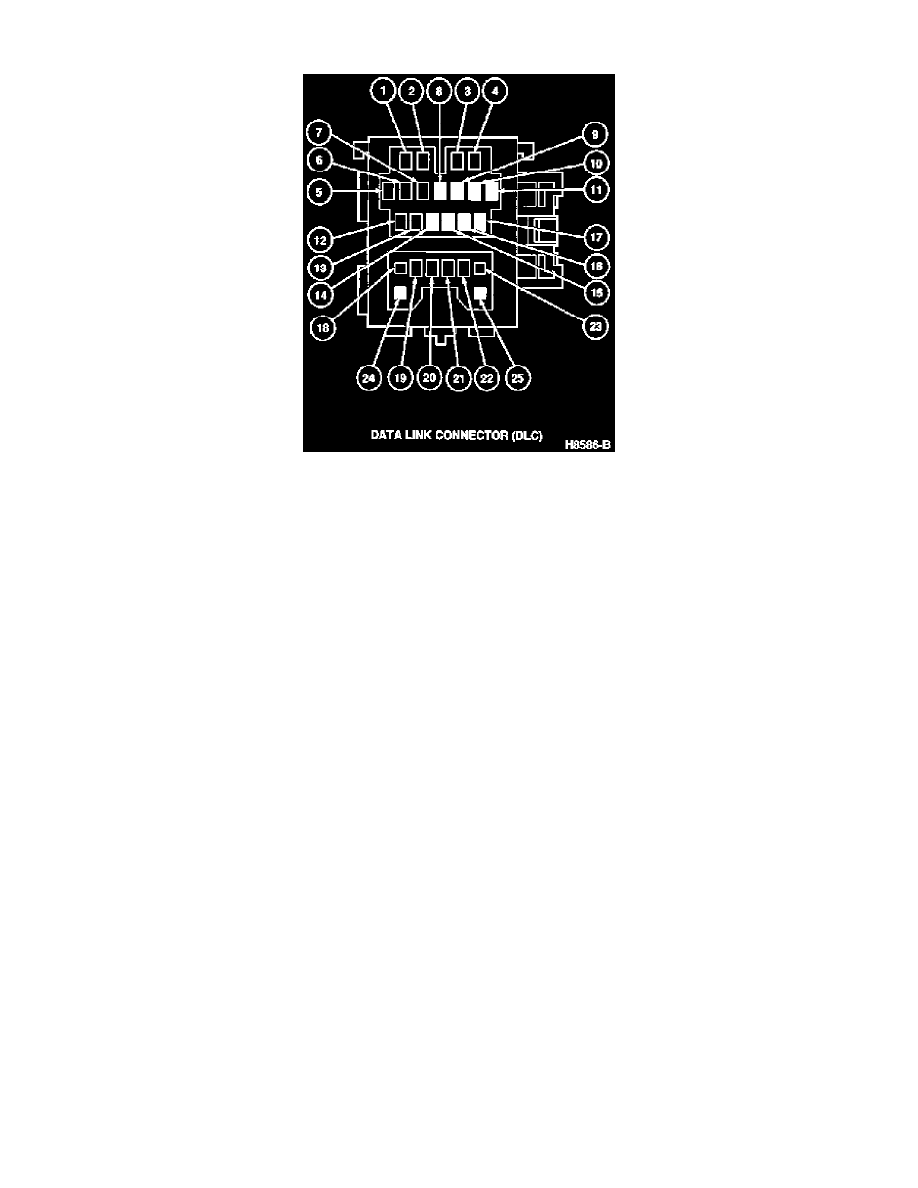
Pin
Circuit
Circuit Function
1
711 (LG/R)
(FEN) PCM Self-Test Output (2.5L Only)
2
712 (W/R)
(MEN) Switch Monitor Lamp (2.5L Only)
3
715 (R/W)
(TEN) PCM Self-Test Input (2.5L Only)
4
41S (BK/Y)
(+B) Battery Voltage
5
60 (BK)
(GND) Ground
6
(*)835 (R)
(FAT) TCM Self-Test Output
7
409 (O/BL)
(FBS) Anti-Lock Brakes Self-Test Output
8
NOT USED
9
NOT USED
10
NOT USED
11
NOT USED
12
(*) 836 (R/BK)
(TAT) TCM Self-Test Input
13
418 (PK/BK)
(TBS) Anti-Lock Brakes Self-Test Input
14
NOT USED
15
NOT USED
16
NOT USED
17
NOT USED
18
952A (R/GN)
(TAB) Air Bag Diagnostic Monitor Output
19
732 (Y/GN)
(IG-) Tachometer Signal (2.5L Only)
20
52Z (BK)
(GND) Ground (2.0L)
54D (BK)
(GND) Ground (2.5L)
21
173A (BL/GN)
(TFA) High Cooling Fan Relay (2.5L Only)
22
704A (LG)
(F/P) Fuel Pump Relay (2.5L Only)
23
323B (GN/O)
(FAB) Horn Relay
24
NOT USED
25
NOT USED
(*) - 2.5L ATX Only