| Diagnosis and Testing Inspection and Verification - Verify the customer concern.
- Visually inspect for the following mechanical and electrical causes for the concern.
Visual Inspection Chart | Mechanical | Electrical | - Refrigerant lines
- Drive belt
- Coolant level
- Blanking cap of coolant system reservoir
- Coolant hoses
| | - Repair any faults found during the visual inspection before proceeding to the next steps.
- If the concern is still present after this check refer to the Symptom Chart and proceed in accordance with the fault symptom.
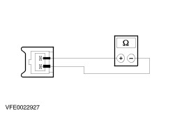
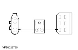
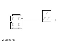
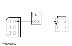
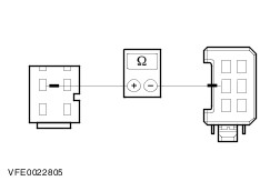
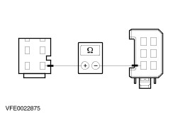
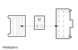
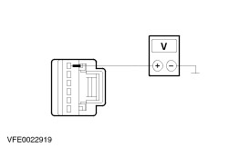
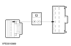
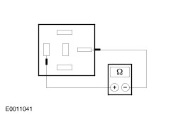
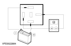
Symptom Chart | Symptom | Possible Sources | Action | | Malfunction of the heater | * Fuse(s) * Heater control module * Heater control valve * Circuit(s) | * | | Malfunction of the heater blower | * Circuit(s) * Heater blower motor * Heater blower switch * Heater blower resistor | * | | Air conditioning inoperative (heater blower motor OK) | * Fuse(s) * Circuit(s) * A/C compressor clutch * A/C compressor clutch diode * A/C relay * A/C WOT relay * A/C compressor switch * Dual pressure switch * Heater control module * PCM/EEC. * Refrigerant circuit * Quantity of refrigerant | * | | Inadequate performance from the air conditioning system | * Condenser * Radiator fan control * A/C compressor switch * Dual pressure switch * Refrigerant circuit * Quantity of refrigerant | * CHECK the refrigerant circuit. For more information please refer to the Component Checks at the end of this diagnosis section. | | Malfunction of the air recirculation valve | * Fuse(s) * Circuit(s) * Air recirculation valve control motor * Heater control module | * | | Condensation water from the air conditioning system in the footwell | * A/C outlet line | * Check that the air conditioning outlet line is routed correctly. | Pinpoint Tests | PINPOINT TEST A : MALFUNCTION OF THE HEATER | | TEST CONDITIONS | DETAILS/RESULTS/ACTIONS | | A1: DETERMINE THE CONDITIONS UNDER WHICH THE FAULT OCCURS | | | 1 Check the operation of the heater. | | | Is the heater permanently cold? Yes No The heater is permanently hot: GO to A2. | | A2: CHECK THE HEATER CONTROL VALVE | WARNING:The heater control valve may be very hot. | NOTE:The heater control valve reacts with a delay to changes in the temperature selection. | | | 1 Ignition switch in position II. | | | 2 Start the engine. | | | 3 Set the temperature control switch to the middle temperature. | | | 4 With the engine running, check to see whether the heater control valve is pulsing. | | | Is the valve pulsing? Yes REMOVE the heater control valve, CHECK for blockages and RENEW as required. CHECK the operation of the system. No | | A3: CHECK FUSE F13 | | | 1 Ignition switch in position 0. | | | 2 CHECK Fuse F13 (CJB). | | | 3 Check fuse F13 (15 A) | | | Is the fuse OK? Yes No RENEW fuse F13 (15 A). CHECK the operation of the system. If the fuse blows again immediately after installing, LOCATE and RECTIFY short circuit to ground with the aid of the Wiring Diagrams Binder. | | A4: CHECK THE VOLTAGE SUPPLY TO FUSE F13 | | | 1 Connect Fuse F13 (CJB). | | | 2 Ignition switch in position II. | | | 3 Measure the voltage between fuse F13 (15 A) and ground. | | | Is battery voltage displayed? Yes No REPAIR the voltage supply to fuse F13 with the aid of the Wiring Diagrams Binder. CHECK the operation of the system. | | A5: CHECK FUSE F2 | | | 1 Ignition switch in position 0. | | | 2 CHECK Fuse F2 (CJB). | | | 3 Check fuse F2 (10 A) | | | Is the fuse OK? Yes No RENEW fuse F2 (10 A). CHECK the operation of the system. If the fuse blows again immediately after installing, LOCATE and RECTIFY short circuit to ground with the aid of the Wiring Diagrams Binder. | | A6: CHECK THE VOLTAGE SUPPLY TO FUSE F2 | | | 1 Connect Fuse F2 (CJB). | | | 2 Measure the voltage between fuse F2 (10 A) and ground. | | | Is battery voltage displayed? Yes No REPAIR the voltage supply to fuse F2 with the aid of the Wiring Diagrams Binder. CHECK the operation of the system. | | A7: CHECK THE VOLTAGE AT THE HEATER CONTROL VALVE | | | 1 Ignition switch in position 0. | | | 2 Disconnect Heater control valve (C42). | | | 3 Ignition switch in position II. | | | 4 Measure the voltage between the heater control valve, connector C42, pin 1, circuit 14-CA82 (VT/BK), wiring harness side and ground. | | | Is battery voltage displayed? Yes No LOCATE and RECTIFY open circuit in circuit 14-CA82 (VT/BK) between the heater control valve and fuse F13 with the aid of the Wiring Diagrams Binder. CHECK the operation of the system. | | A8: CHECK THE HEATER CONTROL VALVE | | | 1 Ignition switch in position 0. | | | 2 Measure the resistance between the heater control valve, connector C42, pin 1 and pin 2, component side. | | | Does the reading show a resistance between 10 and 25 Ohm? Yes No RENEW the heater control valve. CHECK the operation of the system. | | A9: CHECK THE HEATER CONTROL VALVE | | | 1 Ignition switch in position II. | | | 2 Start the engine. | | | 3 Set the temperature control switch to the middle temperature. | | | 4 Measure the voltage between the heater control valve, connector C42, pin 1, circuit 14-CA82 (VT/BK) and pin 2, circuit 31S-CA82 (BK/GN), wiring harness side. | | | Does the measurement vary periodically between 0 Volt and battery voltage? Yes REMOVE the heater control valve, CHECK for blockages and RENEW as required. CHECK the operation of the system. No | | A10: CHECK THE VOLTAGE SUPPLY TO THE HEATER CONTROL MODULE | | | 1 Ignition switch in position 0. | | | 2 Disconnect Heater control module C41. | | | 3 Ignition switch in position II. | | | 4 Measure the voltage between the heater control module, connector C41, pin 12, circuit 14-CA45A (VT), wiring harness side and ground. | | | Is battery voltage displayed? Yes No LOCATE and RECTIFY open circuit in circuit 14-CA45A (VT) between the heater control module and fuse F13 with the aid of the Wiring Diagrams Binder. CHECK the operation of the system. | | A11: CHECK THE VOLTAGE SUPPLY TO THE HEATER CONTROL MODULE | | | 1 Ignition switch in position 0. | | | 2 Measure the voltage between the heater control module, connector C41, pin 2, circuit 29-CA83 (OG/GN), wiring harness side and ground. | | | Is battery voltage displayed? Yes No LOCATE and RECTIFY open circuit in circuit 29-CA83 (OG/GN) between the heater control module and fuse F2 with the aid of the Wiring Diagrams Binder. CHECK the operation of the system. | | A12: CHECK THE GROUND CONNECTION OF THE HEATER CONTROL MODULE | | | 1 Measure the resistance between the heater control module, connector C41, pin 6, circuit 91-CA83 (BK/RD), wiring harness side and ground. | | | Is less than 2 Ohm displayed? Yes No LOCATE and RECTIFY open circuit in circuit 91-CA83 (BK/RD) between the heater control module and ground connection G4 with the aid of the Wiring Diagrams Binder. CHECK the operation of the system. | | A13: CHECK THE CONTROL LINE BETWEEN THE HEATER CONTROL MODULE AND THE HEATER CONTROL VALVE | | | 1 Measure the resistance between the heater control module, connector C41, pin 5, circuit 31S-CA82 (BK/GN), wiring harness side and the heater control valve, connector C42, pin 2, circuit 31S-CA82 (BK/GN), wiring harness side. | | | Is less than 2 Ohm displayed? Yes CHECK and if necessary RENEW the heater control module. CHECK the operation of the system. No LOCATE and RECTIFY open circuit in circuit 31S-CA82 (BK/GN) between the heater control module and the heater control valve with the aid of the Wiring Diagrams Binder. CHECK the operation of the system. | | A14: CHECK THE HEATER CONTROL VALVE | | | 1 Ignition switch in position 0. | | | 2 Disconnect Heater control valve (C42). | | | 3 Ignition switch in position II. | | | 4 Start the engine. | | | 5 Set the temperature switch to the highest setting. | | | 6 Check the operation of the heater. | | | Does the heater warm up? Yes No CHECK whether the coolant hoses are routed correctly. If the coolant circuit is OK, REMOVE the heater control valve, CHECK for blockages and if necessary RENEW. CHECK the operation of the system. | | A15: CHECK THE HEATER CONTROL MODULE | | | 1 Ignition switch in position 0. | | | 2 Connect Heater control valve C42. | | | 3 Disconnect Heater control module C41. | | | 4 Ignition switch in position II. | | | 5 Start the engine. | | | 6 Set the temperature switch to the highest setting. | | | 7 Check the operation of the heater. | | | Does the heater warm up? Yes No LOCATE and RECTIFY short circuit to ground in circuit 31-CA82 (BK/GN) between the heater control valve and the heater control module with the aid of the Wiring Diagrams Binder. CHECK the operation of the system. | | A16: CHECK THE SIGNAL FROM THE REVOLUTION COUNTER | NOTE:If the heater control module does not receive a signal from the revolution counter then the heater will stay cold permanently. | | | 1 Ignition switch in position II. | | | 2 Start the engine. | | | 3 Measure the voltage between the heater control module, connector C41, pin 1, circuit 8-GB10A (WH/BK), wiring harness side and ground. | | | Is a voltage of 7 Volt displayed? Yes CHECK and if necessary RENEW the heater control module. CHECK the operation of the system. No LOCATE and RECTIFY open circuit in circuit 8-GB10A (WH/BK) between the heater control module and the instrument cluster with the aid of the Wiring Diagrams Binder. If the circuit is OK, CHECK the instrument cluster. CHECK the operation of the system. | | PINPOINT TEST B : MALFUNCTION OF THE HEATER BLOWER | | TEST CONDITIONS | DETAILS/RESULTS/ACTIONS | | B1: DETERMINE THE CONDITIONS UNDER WHICH THE FAULT OCCURS | | | 1 Ignition switch in position II. | | | 2 Test all of the speeds of the heater blower motor. | | | Is the heater blower motor completely inoperative? Yes No | | B2: CHECK FUSE F16 | | | 1 Ignition switch in position 0. | | | 2 CHECK Fuse F16 (CJB). | | | 3 Check fuse F16 (30 A) | | | Is the fuse OK? Yes No RENEW fuse F16 (30 A). CHECK the operation of the system. If the fuse blows again immediately after installing, LOCATE and RECTIFY short circuit to ground with the aid of the Wiring Diagrams Binder. | | B3: CHECK THE VOLTAGE SUPPLY TO FUSE F16 | | | 1 Connect Fuse F16 (CJB). | | | 2 Ignition switch in position II. | | | 3 Measure the voltage between fuse F16 (30 A) and ground. | | | Is battery voltage displayed? Yes No REPAIR the voltage supply to fuse F16 with the aid of the Wiring Diagrams Binder. CHECK the operation of the system. | | B4: CHECK THE VOLTAGE SUPPLY TO THE BLOWER MOTOR | | | 1 Ignition switch in position 0. | | | 2 Disconnect Heater blower motor C221. | | | 3 Ignition switch in position II. | | | 4 Measure the voltage between the blower motor, connector C221, pin 1, circuit 14-CA18 (VT/OG), wiring harness side and ground. | | | Is battery voltage displayed? Yes No LOCATE and RECTIFY open circuit in circuit 14-CA18 (VT/OG) between the heater blower motor and fuse F16 with the aid of the Wiring Diagrams Binder. CHECK the operation of the system. | | B5: CHECK THE GROUND CONNECTION OF THE HEATER BLOWER MOTOR | | | 1 Ignition switch in position 0. | | | 2 Set the heater blower switch to the highest speed setting. | | | 3 Measure the resistance between the heater blower motor C221, pin 2, circuit 31S-CA18 (BK/RD), wiring harness side and ground. | | | Is less than 2 Ohm displayed? Yes CHECK and if necessary RENEW the heater blower motor. CHECK the operation of the system No | | B6: CHECK THE CONNECTION BETWEEN THE HEATER BLOWER MOTOR AND THE HEATER BLOWER SWITCH | | | 1 Disconnect Heater blower switch C38. | | | 2 Measure the resistance between the heater blower motor, connector C221, pin 2, circuit 31S-CA18 (BK/RD), wiring harness side and the heater blower switch, connector C38, pin 4, circuit 31S-CA33 (BK/OG), wiring harness side. | | | Is less than 2 Ohm displayed? Yes No LOCATE and RECTIFY open circuit in circuit 31S-CA18 (BK/RD) between the heater blower motor and the heater blower switch with the aid of the Wiring Diagrams Binder. CHECK the operation of the system. | | B7: CHECK THE GROUND CONNECTION OF THE HEATER BLOWER SWITCH | | | 1 Measure the resistance between the heater blower switch, connector C38, pin 6, circuit 31-CA25 (BK), wiring harness side and ground. | | | Is less than 2 Ohm displayed? Yes CHECK and if necessary RENEW the heater blower switch. CHECK the operation of the system No LOCATE and RECTIFY open circuit in circuit 31-CA25 (BK) between the heater blower switch and ground connection G6 with the aid of the Wiring Diagrams Binder. CHECK the operation of the system. | | B8: CHECK THE CONNECTION BETWEEN THE HEATER BLOWER MOTOR AND THE HEATER BLOWER SWITCH | | | 1 Disconnect Heater blower switch C1038. | | | 2 Measure the resistance between the heater blower motor, connector C221, pin 2, circuit 31S-CA18 (BK/RD), wiring harness side and the heater blower switch, connector C1038, pin 6, circuit 31S-CA33 (BK/OG), wiring harness side. | | | Is less than 2 Ohm displayed? Yes No LOCATE and RECTIFY open circuit in circuit 31S-CA18 (BK/RD) between the heater blower motor and the heater blower switch with the aid of the Wiring Diagrams Binder. CHECK the operation of the system. | | B9: CHECK THE GROUND CONNECTION OF THE HEATER BLOWER SWITCH | | | 1 Measure the resistance between the heater blower switch, connector C1038, pin 2, circuit 31-CA25 (BK), wiring harness side and ground. | | | Is less than 2 Ohm displayed? Yes CHECK and if necessary RENEW the heater blower switch. CHECK the operation of the system No LOCATE and RECTIFY open circuit in circuit 31-CA25 (BK) between the heater blower switch and ground connection G6 with the aid of the Wiring Diagrams Binder. CHECK the operation of the system. | | B10: DETERMINE THE CONDITIONS UNDER WHICH THE FAULT OCCURS | | | 1 Ignition switch in position II. | | | 2 Set the heater blower switch to the highest speed setting. | | | Is the heater blower motor inoperative? Yes No | | B11: CHECK THE CONNECTION BETWEEN THE HEATER BLOWER MOTOR AND THE HEATER BLOWER SWITCH | | | 1 Ignition switch in position 0. | | | 2 Disconnect Heater blower switch C38. | | | 3 Disconnect Heater blower motor C221. | | | 4 Measure the resistance between the heater blower motor, connector C221, pin 2, circuit 31S-CA18 (BK/RD), wiring harness side and the heater blower switch, connector C38, pin 4, circuit 31S-CA33 (BK/OG), wiring harness side. | | | Is less than 2 Ohm displayed? Yes CHECK and if necessary RENEW the heater blower switch. CHECK the operation of the system No LOCATE and RECTIFY open circuit in circuit 31S-CA33 (BK/OG) between the heater blower motor and the heater blower switch with the aid of the Wiring Diagrams Binder. CHECK the operation of the system. | | B12: CHECK THE CONNECTION BETWEEN THE HEATER BLOWER MOTOR AND THE HEATER BLOWER SWITCH | | | 1 Ignition switch in position 0. | | | 2 Disconnect Heater blower switch C1038. | | | 3 Disconnect Heater blower motor C221. | | | 4 Measure the resistance between the heater blower motor, connector C221, pin 2, circuit 31S-CA18 (BK/RD), wiring harness side and the heater blower switch, connector C1038, pin 6, circuit 31S-CA33 (BK/OG), wiring harness side. | | | Is less than 2 Ohm displayed? Yes CHECK and if necessary RENEW the heater blower switch. CHECK the operation of the system No LOCATE and RECTIFY open circuit in circuit 31S-CA33 (BK/OG) between the heater blower motor and the heater blower switch with the aid of the Wiring Diagrams Binder. CHECK the operation of the system. | | B13: CHECK THE HEATER BLOWER SWITCH | | | 1 Ignition switch in position 0. | | | 2 Disconnect Heater blower switch C38. | | | 3 Ignition switch in position II. | | | 4 Measure the voltage between the heater blower switch, connector C38, pin 1, circuit 31S-CA32 (BK/BU), wiring harness side and ground. | | | 5 Measure the voltage between the heater blower switch, connector C38, pin 2, circuit 31S-CA31 (BK/YE), wiring harness side and ground. | | | 6 Measure the voltage between the heater blower switch, connector C38, pin 3, circuit 31S-CA30 (BK/WH), wiring harness side and ground. | | | Is battery voltage displayed in all measurements? Yes CHECK and if necessary RENEW the heater blower switch. CHECK the operation of the system No | | B14: CHECK THE CONNECTION BETWEEN THE HEATER BLOWER MOTOR AND THE HEATER BLOWER RESISTOR | | | 1 Ignition switch in position 0. | | | 2 Disconnect Heater blower resistor C220. | | | 3 Ignition switch in position II. | | | 4 Measure the voltage between the heater blower resistor, connector C220, pin 1, circuit 31S-CA18A (BK/RD), wiring harness side and ground. | | | Is battery voltage displayed? Yes No LOCATE and RECTIFY open circuit in circuit 31S-CA18A (BK/RD) between the heater blower motor and the heater blower resistor with the aid of the Wiring Diagrams Binder. CHECK the operation of the system. | | B15: CHECK THE CONNECTION BETWEEN THE HEATER BLOWER RESISTOR AND THE HEATER BLOWER SWITCH | | | 1 Ignition switch in position 0. | | | 2 Measure the resistance between the heater blower resistor, connector C220, pin 4, circuit 31S-CA32 (BK/BU), wiring harness side and the heater blower switch, connector C38, pin 1, circuit 31S-CA32 (BK/BU), wiring harness side. | | | Is less than 2 Ohm displayed? Yes No LOCATE and RECTIFY open circuit in circuit 31S-CA32 (BK/BU) between the heater blower resistor and the heater blower switch with the aid of the Wiring Diagrams Binder. CHECK the operation of the system. | | B16: CHECK THE CONNECTION BETWEEN THE HEATER BLOWER RESISTOR AND THE HEATER BLOWER SWITCH | | | 1 Measure the resistance between the heater blower resistor, connector C220, pin 2, circuit 31S-CA31 (BK/YE), wiring harness side and the heater blower switch, connector C38, pin 2, circuit 31S-CA31 (BK/YE), wiring harness side. | | | Is less than 2 Ohm displayed? Yes No LOCATE and RECTIFY open circuit in circuit 31S-CA31 (BK/YE) between the heater blower resistor and the heater blower switch with the aid of the Wiring Diagrams Binder. CHECK the operation of the system. | | B17: CHECK THE CONNECTION BETWEEN THE HEATER BLOWER RESISTOR AND THE HEATER BLOWER SWITCH | | | 1 Measure the resistance between the heater blower resistor, connector C220, pin 3, circuit 31S-CA30 (BK/WH), wiring harness side and the heater blower switch, connector C38, pin 3, circuit 31S-CA30 (BK/WH), wiring harness side. | | | Is less than 2 Ohm displayed? Yes CHECK and if necessary RENEW the heater blower resistor. CHECK the operation of the system No LOCATE and RECTIFY open circuit in circuit 31S-CA30 (BK/YE) between the heater blower resistor and the heater blower switch with the aid of the Wiring Diagrams Binder. CHECK the operation of the system. | | B18: CHECK THE HEATER BLOWER SWITCH | | | 1 Ignition switch in position 0. | | | 2 Disconnect Heater blower switch C1038. | | | 3 Ignition switch in position II. | | | 4 Measure the voltage between the heater blower switch, connector C1038, pin 5, circuit 31S-CA32 (BK/BU), wiring harness side and ground. | | | 5 Measure the voltage between the heater blower switch, connector C1038, pin 3, circuit 31S-CA31 (BK/YE), wiring harness side and ground. | | | 6 Measure the voltage between the heater blower switch, connector C1038, pin 1, circuit 31S-CA30 (BK/WH), wiring harness side and ground. | | | Is battery voltage displayed in all measurements? Yes CHECK and if necessary RENEW the heater blower switch. CHECK the operation of the system No | | B19: CHECK THE CONNECTION BETWEEN THE HEATER BLOWER MOTOR AND THE HEATER BLOWER RESISTOR | | | 1 Ignition switch in position 0. | | | 2 Disconnect Heater blower resistor C220. | | | 3 Ignition switch in position II. | | | 4 Measure the voltage between the heater blower resistor, connector C220, pin 1, circuit 31S-CA18A (BK/RD), wiring harness side and ground. | | | Is battery voltage displayed? Yes No LOCATE and RECTIFY open circuit in circuit 31S-CA18A (BK/RD) between the heater blower motor and the heater blower resistor with the aid of the Wiring Diagrams Binder. CHECK the operation of the system. | | B20: CHECK THE CONNECTION BETWEEN THE HEATER BLOWER RESISTOR AND THE HEATER BLOWER SWITCH | | | 1 Ignition switch in position 0. | | | 2 Measure the resistance between the heater blower resistor, connector C220, pin 4, circuit 31S-CA32 (BK/BU), wiring harness side and the heater blower switch, connector C1038, pin 5, circuit 31S-CA32 (BK/BU), wiring harness side. | | | Is less than 2 Ohm displayed? Yes No LOCATE and RECTIFY open circuit in circuit 31S-CA32 (BK/BU) between the heater blower resistor and the heater blower switch with the aid of the Wiring Diagrams Binder. CHECK the operation of the system. | | B21: CHECK THE CONNECTION BETWEEN THE HEATER BLOWER RESISTOR AND THE HEATER BLOWER SWITCH | | | 1 Measure the resistance between the heater blower resistor, connector C220, pin 3, circuit 31S-CA31 (BK/YE), wiring harness side and the heater blower switch, connector C1038, pin 2, circuit 31S-CA31 (BK/YE), wiring harness side. | | | Is less than 2 Ohm displayed? Yes No LOCATE and RECTIFY open circuit in circuit 31S-CA31 (BK/YE) between the heater blower resistor and the heater blower switch with the aid of the Wiring Diagrams Binder. CHECK the operation of the system. | | B22: CHECK THE CONNECTION BETWEEN THE HEATER BLOWER RESISTOR AND THE HEATER BLOWER SWITCH | | | 1 Measure the resistance between the heater blower resistor, connector C220, pin 1, circuit 31S-CA30 (BK/WH), wiring harness side and the heater blower switch, connector C1038, pin 3, circuit 31S-CA30 (BK/WH), wiring harness side. | | | Is less than 2 Ohm displayed? Yes CHECK and if necessary RENEW the heater blower resistor. CHECK the operation of the system No LOCATE and RECTIFY open circuit in circuit 31S-CA30 (BK/YE) between the heater blower resistor and the heater blower switch with the aid of the Wiring Diagrams Binder. CHECK the operation of the system. | | PINPOINT TEST C : AIR CONDITIONING INOPERATIVE (HEATER BLOWER OK) | | TEST CONDITIONS | DETAILS/RESULTS/ACTIONS | | C1: CHECK FUSE F2 | | | 1 Ignition switch in position 0. | | | 2 CHECK Fuse F2 (CJB). | | | 3 Check fuse F2 (10 A) | | | Is the fuse OK? Yes No RENEW fuse F2 (10 A). CHECK the operation of the system. If the fuse blows again immediately after installing, LOCATE and RECTIFY short circuit to ground with the aid of the Wiring Diagrams Binder. | | C2: MEASURE THE VOLTAGE AT FUSE F2 | | | 1 Connect Fuse F2 (CJB). | | | 2 Ignition switch in position II. | | | 3 Measure the voltage between fuse F2 (10 A) and ground. | | | Is battery voltage displayed? Yes No REPAIR the voltage supply to fuse F2 with the aid of the Wiring Diagrams Binder. CHECK the operation of the system. | | C3: CHECK FUSE F13 | | | 1 Ignition switch in position 0. | | | 2 CHECK Fuse F13 (CJB). | | | 3 Check fuse F13 (15 A) | | | Is the fuse OK? Yes No RENEW fuse F13 (15 A). CHECK the operation of the system. If the fuse blows again immediately after installing, LOCATE and RECTIFY short circuit to ground with the aid of the Wiring Diagrams Binder. | | C4: CHECK VOLTAGE AT FUSE F13 | | | 1 Connect Fuse F13 (CJB). | | | 2 Ignition switch in position II. | | | 3 Measure the voltage between fuse F13 (15 A) and ground. | | | Is battery voltage displayed? Yes No REPAIR the voltage supply to fuse F13 with the aid of the Wiring Diagrams Binder. CHECK the operation of the system. | | C5: CHECK FUSE F28 | | | 1 Ignition switch in position 0. | | | 2 CHECK Fuse F28 (BJB). | | | 3 Check fuse F28 (15 A) | | | Is the fuse OK? Yes No RENEW fuse F28 (15 A). CHECK the operation of the system. If the fuse blows again immediately after installing, LOCATE and RECTIFY short circuit to ground with the aid of the Wiring Diagrams Binder. | | C6: CHECK VOLTAGE AT FUSE F28 | | | 1 Connect Fuse F28 (BJB). | | | 2 Ignition switch in position II. | | | 3 Measure the voltage between fuse F28 (15 A) and ground. | | | Is battery voltage displayed? Yes No REPAIR the voltage supply to fuse F28 with the aid of the Wiring Diagrams Binder. CHECK the operation of the system. | | C7: CHECK FUSE F29 | | | 1 Ignition switch in position 0. | | | 2 CHECK Fuse F29 (BJB). | | | 3 Check fuse F29 (20 A) | | | Is the fuse OK? Yes No RENEW fuse F29 (20 A). CHECK the operation of the system. If the fuse blows again immediately after installing, CHECK and if necessary RENEW the A/C compressor clutch diode. If the diode is OK, LOCATE and RECTIFY short circuit to ground with the aid of the Wiring Diagrams Binder. | | C8: CHECK VOLTAGE AT FUSE F29 | | | 1 Connect Fuse F29 (BJB). | | | 2 Ignition switch in position II. | | | 3 Measure the voltage between fuse F29 (20 A) and ground. | | | Is battery voltage displayed? Yes No REPAIR the voltage supply to fuse F29 with the aid of the Wiring Diagrams Binder. CHECK the operation of the system. | | C9: CHECK FUSE F30 | | | 1 Ignition switch in position 0. | | | 2 CHECK Fuse F28 (BJB). | | | 3 Check fuse F30 (15 A) | | | Is the fuse OK? Yes No RENEW fuse F30 (15 A). CHECK the operation of the system. If the fuse blows again immediately after installing, LOCATE and RECTIFY short circuit to ground with the aid of the Wiring Diagrams Binder. | | C10: CHECK THE VOLTAGE AT FUSE F30 | | | 1 Connect Fuse F30 (BJB). | | | 2 Ignition switch in position II. | | | 3 Measure the voltage between fuse F30 (15 A) and ground. | | | Is battery voltage displayed? Yes No REPAIR the voltage supply to fuse F30 with the aid of the Wiring Diagrams Binder. CHECK the operation of the system. | | C11: CHECK FUSE F31 | | | 1 Ignition switch in position 0. | | | 2 CHECK Fuse F31 (BJB). | | | 3 Check fuse F31 (20 A) | | | Is the fuse OK? Yes No RENEW fuse F31 (20 A). CHECK the operation of the system. If the fuse blows again immediately after installing, CHECK and if necessary RENEW the A/C compressor clutch diode. If the diode is OK, LOCATE and RECTIFY short circuit to ground with the aid of the Wiring Diagrams Binder. | | C12: CHECK VOLTAGE AT FUSE F31 | | | 1 Connect Fuse F31 (BJB). | | | 2 Ignition switch in position II. | | | 3 Measure the voltage between fuse F31 (20 A) and ground. | | | Is battery voltage displayed? Yes No REPAIR the voltage supply to fuse F31 with the aid of the Wiring Diagrams Binder. CHECK the operation of the system. | | C13: CHECK THE VOLTAGE SUPPLY TO THE A/C WOT RELAY | | | 1 Ignition switch in position 0. | | | 2 Disconnect WOT relay C165. | | | 3 Ignition switch in position II. | | | 4 Measure the voltage between the WOT relay, connector C165, pin 1, circuit 94S-CA11 (VT/YE), wiring harness side and ground. | | | Is battery voltage displayed? Yes No LOCATE and RECTIFY open circuit in circuit 94S-CA11 (VT/YE) between the WOT relay and fuse F28 (vehicles built before 02/00) or F30 (vehicles built from 02/00) with the aid of the Wiring Diagrams Binder. CHECK the operation of the system. | | C14: CHECK THE VOLTAGE SUPPLY TO THE A/C WOT RELAY | | | 1 Measure the voltage between the WOT relay, connector C165, pin 5, circuit 14S-CA12 (VT/BU), wiring harness side and ground. | | | Is battery voltage displayed? Yes No | | C15: CHECK THE VOLTAGE SUPPLY TO THE DUAL PRESSURE SWITCH | | | 1 Ignition switch in position 0. | | | 2 Disconnect Dual pressure switch C96. | | | 3 Ignition switch in position II. | | | 4 Measure the voltage between the dual pressure switch, connector C96, pin 4, circuit 14-CA38 (VT), wiring harness side and ground. | | | Is battery voltage displayed? Yes No LOCATE and RECTIFY open circuit in circuit 14-CA38 (VT) between the dual pressure switch and fuse F29 (vehicles built before 02/00) or F31 (vehicles built from 02/00) with the aid of the Wiring Diagrams Binder. CHECK the operation of the system. | | C16: CHECK THE DUAL PRESSURE SWITCH | | | 1 Ignition switch in position 0. | | | 2 Measure the resistance between the dual pressure switch, connector C96, pin 2 and pin 4, component side. | | | Is less than 2 Ohm displayed? Yes LOCATE and RECTIFY open circuit in circuit 14S-CA12 (VT/BU) between the WOT relay and the dual pressure switch with the aid of the Wiring Diagrams Binder. CHECK the operation of the system. No CHECK and if necessary RENEW the dual pressure switch. If the dual pressure switch is OK, CHECK and if necessary REPAIR the refrigerant circuit. CHECK the operation of the system. | | C17: CHECK THE A/C COMPRESSOR | | | 1 Use a cable link to bridge the WOT relay, connector C165, between pin 5, circuit 14S-CA12 (VT/BU) and pin 3, circuit 14S-CA1 (VT/BU), wiring harness side. | | | Is the A/C compressor on? Yes No | | C18: CHECK THE VOLTAGE SUPPLY TO THE A/C COMPRESSOR CLUTCH | | | 1 Ignition switch in position 0. | | | 2 Disconnect A/C compressor clutch C94. | | | 3 Connect WOT relay C165. | | | 4 Ignition switch in position II. | | | 5 Switch on the heater blower. | | | 6 Switch on the air conditioning. | | | 7 Measure the voltage between the A/C compressor clutch, connector C94, circuit 14S-CA6 (VT/YE), wiring harness side and ground. | | | Is battery voltage displayed? Yes No LOCATE and RECTIFY open circuit in circuit 14S-CA6 (VT/YE) between the WOT relay and the A/C compressor clutch with the aid of the Wiring Diagrams Binder. CHECK the operation of the system. | | C19: CHECK THE GROUND CONNECTION OF THE A/C COMPRESSOR CLUTCH | | | 1 Ignition switch in position 0. | | | 2 Measure the resistance between the A/C compressor clutch, connector C94, circuit 31-CA6 (BK), wiring harness side and ground. | | | Is less than 2 Ohm displayed? Yes CHECK and if necessary RENEW the A/C compressor clutch. CHECK the operation of the system. No LOCATE and RECTIFY open circuit in circuit 31-CA6 (BK) between the A/C compressor clutch and ground connection G11. CHECK the operation of the system. | | C20: CHECK THE CONNECTION BETWEEN THE WOT RELAY AND THE PCM. | | | 1 Switch on the heater blower. | | | 2 Switch on the air conditioning. | | | 3 Measure the resistance between the WOT relay, socket C165, pin 2, circuit 31S-CA11 (BK/YE), wiring harness side and ground. | | | Is less than 1000 Ohm displayed? Yes CHECK and if necessary RENEW the WOT relay. CHECK the operation of the system No | | C21: CHECK THE VOLTAGE SUPPLY TO THE A/C RELAY | | | 1 Disconnect A/C relay C162. | | | 2 Ignition switch in position II. | | | 3 Measure the voltage between the A/C relay, connector C162, pin 2, circuit 94S-CA66 (VT/OG), wiring harness side and ground. | | | Is battery voltage displayed? Yes No LOCATE and RECTIFY open circuit in circuit 94S-CA66 (VT/OG) between the A/C relay and fuse F28 (vehicles built before 02/00) or F30 (vehicles built from 02/00) with the aid of the Wiring Diagrams Binder. CHECK the operation of the system. | | C22: CHECK THE VOLTAGE SUPPLY TO THE A/C RELAY | | | 1 Measure the voltage between the A/C relay, connector C162, pin 3, circuit 14S-CA67 (VT/BK), wiring harness side and ground. | | | Is battery voltage displayed? Yes No LOCATE and RECTIFY open circuit in circuit 14S-CA67 (VT/BK) between the A/C relay and fuse F29 (vehicles built before 02/00) or F31 (vehicles built from 02/00) with the aid of the Wiring Diagrams Binder. CHECK the operation of the system. | | C23: CHECK THE GROUND CONNECTION OF THE A/C RELAY | | | 1 Switch on the heater blower. | | | 2 Switch on the air conditioning. | | | 3 Measure the voltage between the A/C relay, socket C162, pin 1, circuit 31S-CA66 (BK/RD), wiring harness side and ground. | | | Is less than 2 V displayed? Yes No | | C24: CHECK THE CONNECTION BETWEEN THE A/C RELAY AND THE HEATER CONTROL MODULE | | | 1 Ignition switch in position 0. | | | 2 Disconnect Heater control module C41. | | | 3 Measure the resistance between the A/C relay, socket C162, pin 1, circuit 31S-CA66 (BK/RD), wiring harness side and the heater control module, connector C41, pin 11, circuit 31S-CA66 (BK/RD), wiring harness side. | | | Is less than 2 Ohm displayed? Yes No LOCATE and RECTIFY open circuit in circuit 31S-CA66 (BK/RD) between the A/C relay and the heater control module with the aid of the Wiring Diagrams Binder. CHECK the operation of the system. | | C25: CHECK THE VOLTAGE SUPPLY TO THE HEATER CONTROL MODULE | | | 1 Ignition switch in position II. | | | 2 Measure the voltage between the heater control module, connector C41, pin 12, circuit 14-CA45A (VT), wiring harness side and ground. | | | Is battery voltage displayed? Yes No LOCATE and RECTIFY open circuit in circuit 14-CA45A (VT) between the heater control module and fuse F13 with the aid of the Wiring Diagrams Binder. CHECK the operation of the system. | | C26: CHECK THE VOLTAGE SUPPLY TO THE HEATER CONTROL MODULE | | | 1 Measure the voltage between the heater control module, connector C41, pin 2, circuit 29-CA83 (OG/GN), wiring harness side and ground. | | | Is battery voltage displayed? Yes No LOCATE and RECTIFY open circuit in circuit 29-CA83 (OG/GN) between the heater control module and fuse F2 with the aid of the Wiring Diagrams Binder. CHECK the operation of the system. | | C27: CHECK THE CONTROL VOLTAGE FROM THE HEATER BLOWER SWITCH | | | 1 Switch on the heater blower. | | | 2 Measure the voltage between the heater control module, connector C41, pin 7, circuit 31S-CA25 (BK/GN), wiring harness side and ground. | | | Is battery voltage displayed? Yes CHECK and if necessary RENEW the heater control module. CHECK the operation of the system No LOCATE and RECTIFY open circuit in circuit 31S-CA25 (BK/GN) between the heater control module and the heater blower switch with the aid of the Wiring Diagrams Binder. CHECK the operation of the system. | | C28: CHECK THE A/C CONTROL CIRCUIT | | | 1 Use a cable link to bridge the A/C relay, connector C162, between pin 5, circuit 14S-CA17 (VT/OG) and pin 3, circuit 14-CA67 (VT/BK), wiring harness side. | | | Is the A/C compressor on? Yes CHECK and if necessary RENEW the A/C relay. CHECK the operation of the system No | | C29: CHECK THE VOLTAGE SUPPLY TO THE A/C COMPRESSOR SWITCH | | | 1 Ignition switch in position 0. | | | 2 Disconnect A/C compressor switch C95. | | | 3 Connect A/C relay C162. | | | 4 Ignition switch in position II. | | | 5 Measure the voltage between the A/C compressor switch, connector C95, pin 1, circuit 14S-CA17 (VT/OG), wiring harness side and ground. | | | Is battery voltage displayed? Yes No LOCATE and RECTIFY open circuit in circuit 14S-CA17 (VT/OG) between the A/C relay and the A/C compressor switch with the aid of the Wiring Diagrams Binder. CHECK the operation of the system. | | C30: CHECK THE A/C COMPRESSOR SWITCH | | | 1 Ignition switch in position 0. | | | 2 Measure the resistance between the A/C compressor switch, connector C95, pin 1 and pin 4, component side. | | | Is less than 2 Ohm displayed? Yes No CHECK and if necessary RENEW the A/C compressor switch. If the A/C compressor switch is OK, CHECK and if necessary CORRECT the quantity of refrigerant in the system. CHECK the operation of the system. | | C31: CHECK THE CONTROL LINE TO THE PCM | | | 1 Disconnect PCM (C159). | | | 2 Connect A/C compressor switch C95. | | | 3 Ignition switch in position II. | | | 4 Measure the voltage between the PCM, connector C159, pin 41, circuit 14S-PC72 (VT/BU), wiring harness side and ground. | | | Is battery voltage displayed? Yes No LOCATE and RECTIFY open circuit in circuit 14S-PC72 (VT/BU) between the A/C compressor switch and the PCM with the aid of the Wiring Diagrams Binder. CHECK the operation of the system. | | C32: CHECK THE CONTROL LINE OF THE WOT RELAY | | | 1 Measure the voltage between the PCM, connector C159, pin 69, circuit 31S-CA11 (BK/YE), wiring harness side and ground. | | | Is battery voltage displayed? Yes CHECK and if necessary RENEW the PCM. CHECK the operation of the system No LOCATE and RECTIFY open circuit in circuit 31S-CA11 (BK/YE) between the WOT relay and the PCM with the aid of the Wiring Diagrams Binder. CHECK the operation of the system. | | C33: CHECK THE CONTROL LINE TO THE EEC | | | 1 Disconnect EEC C1159. | | | 2 Connect A/C compressor switch C95. | | | 3 Ignition switch in position II. | | | 4 Measure the voltage between the EEC, connector C1159, pin 10, circuit 14S-PC72 (VT/BU), wiring harness side and ground. | | | Is battery voltage displayed? Yes No LOCATE and RECTIFY open circuit in circuit 14S-PC72 (VT/BU) between the A/C compressor switch and the EEC with the aid of the Wiring Diagrams Binder. CHECK the operation of the system. | | C34: CHECK THE CONTROL LINE OF THE WOT RELAY | | | 1 Measure the voltage between the EEC, connector C1159, pin 54, circuit 31S-CA11 (BK/YE), wiring harness side and ground. | | | Is battery voltage displayed? Yes CHECK and if necessary RENEW the EEC. CHECK the operation of the system No LOCATE and RECTIFY open circuit in circuit 31S-CA11 (BK/YE) between the WOT relay and the EEC with the aid of the Wiring Diagrams Binder. CHECK the operation of the system. | | PINPOINT TEST D : MALFUNCTION OF THE AIR RECIRCULATION VALVE | | TEST CONDITIONS | DETAILS/RESULTS/ACTIONS | | D1: CHECK FUSE F2 | | | 1 Ignition switch in position 0. | | | 2 CHECK Fuse F2 (CJB). | | | 3 Check fuse F2 (10 A) | | | Is the fuse OK? Yes No RENEW fuse F2 (10 A). CHECK the operation of the system. If the fuse blows again immediately after installing, LOCATE and RECTIFY short circuit to ground with the aid of the Wiring Diagrams Binder. | | D2: MEASURE THE VOLTAGE AT FUSE F2 | | | 1 Connect Fuse F2 (CJB). | | | 2 Ignition switch in position II. | | | 3 Measure the voltage between fuse F2 (10 A) and ground. | | | Is battery voltage displayed? Yes No REPAIR the voltage supply to fuse F2 with the aid of the Wiring Diagrams Binder. CHECK the operation of the system. | | D3: CHECK FUSE F13 | | | 1 Ignition switch in position 0. | | | 2 CHECK Fuse F13 (CJB). | | | 3 Check fuse F13 (15 A) | | | Is the fuse OK? Yes No RENEW fuse F13 (15 A). CHECK the operation of the system. If the fuse blows again immediately after installing, LOCATE and RECTIFY short circuit to ground with the aid of the Wiring Diagrams Binder. | | D4: CHECK VOLTAGE AT FUSE F13 | | | 1 Connect Fuse F13 (CJB). | | | 2 Ignition switch in position II. | | | 3 Measure the voltage between fuse F13 (15 A) and ground. | | | Is battery voltage displayed? Yes No REPAIR the voltage supply to fuse F13 with the aid of the Wiring Diagrams Binder. CHECK the operation of the system. | | D5: CHECK FUSE F16 | | | 1 Ignition switch in position 0. | | | 2 CHECK Fuse F16 (CJB). | | | 3 Check fuse F16 (30 A) | | | Is the fuse OK? Yes No RENEW fuse F16 (30 A). CHECK the operation of the system. If the fuse blows again immediately after installing, LOCATE and RECTIFY short circuit to ground with the aid of the Wiring Diagrams Binder. | | D6: MEASURE THE VOLTAGE AT FUSE F16 | | | 1 Connect Fuse F16 (CJB). | | | 2 Ignition switch in position II. | | | 3 Measure the voltage between fuse F16 (30 A) and ground. | | | Is battery voltage displayed? Yes No REPAIR the voltage supply to fuse F16 with the aid of the Wiring Diagrams Binder. CHECK the operation of the system. | | D7: CHECK THE VOLTAGE SUPPLY TO THE AIR RECIRCULATION VALVE CONTROL MOTOR | | | 1 Ignition switch in position 0. | | | 2 Disconnect Air recirculation valve control motor C222. | | | 3 Ignition switch in position II. | | | 4 Measure the voltage between the air recirculation valve control motor, connector C222, pin 1, circuit 14-CA76 (VT), wiring harness side and ground. | | | Is battery voltage displayed? Yes No LOCATE and RECTIFY open circuit in circuit 14-CA76 (VT) between the air recirculation valve control motor and fuse F16 with the aid of the Wiring Diagrams Binder. CHECK the operation of the system. | | D8: CHECK THE GROUND CONNECTION OF THE AIR RECIRCULATION VALVE CONTROL MOTOR | | | 1 Ignition switch in position 0. | | | 2 Measure the resistance between the air recirculation valve control motor, connector C222, pin 3, circuit 31-CA76 (BK), wiring harness side and ground. | | | Is less than 2 Ohm displayed? Yes No LOCATE and RECTIFY open circuit in circuit 31-CA76 (BK) between the air recirculation valve control motor and ground connection G13 with the aid of the Wiring Diagrams Binder. CHECK the operation of the system. | | D9: CHECK THE VOLTAGE SUPPLY TO THE AIR RECIRCULATION VALVE CONTROL MOTOR | | | 1 Ignition switch in position II. | | | 2 Set the heater control module to "Air recirculation". | | | 3 Measure the voltage between the air recirculation valve control motor, connector C222, pin 2, circuit 31S-CA76 (BK/OG), wiring harness side and ground. | | | Is battery voltage displayed? Yes CHECK and if necessary RENEW the air recirculation valve control motor. CHECK the operation of the system. No | | D10: CHECK THE CONTROL LINE OF THE AIR RECIRCULATION VALVE CONTROL MOTOR | | | 1 Ignition switch in position 0. | | | 2 Disconnect Heater control module C41. | | | 3 Measure the resistance between the air recirculation valve control motor, connector C222, pin 2, circuit 31S-CA76 (BK/OG) and the heater control module, connector C41, pin 9, circuit 31S-CA76 (BK/OG), wiring harness side. | | | Is less than 2 Ohm displayed? Yes No LOCATE and RECTIFY open circuit in circuit 31S-CA76 (BK/OG) between the air recirculation valve control motor and the heater control module with the aid of the Wiring Diagrams Binder. CHECK the operation of the system. | | D11: CHECK THE VOLTAGE SUPPLY TO THE AIR RECIRCULATION VALVE CONTROL MOTOR | | | 1 Ignition switch in position 0. | | | 2 Disconnect Air recirculation valve control motor C1222. | | | 3 Ignition switch in position II. | | | 4 Measure the voltage between the air recirculation valve control motor, connector C1222, pin 5, circuit 14-CA76 (VT), wiring harness side and ground. | | | Is battery voltage displayed? Yes No LOCATE and RECTIFY open circuit in circuit 14-CA76 (VT) between the air recirculation valve control motor and fuse F16 with the aid of the Wiring Diagrams Binder. CHECK the operation of the system. | | D12: CHECK THE GROUND CONNECTION OF THE AIR RECIRCULATION VALVE CONTROL MOTOR | | | 1 Ignition switch in position 0. | | | 2 Measure the voltage between the air recirculation valve control motor, connector C1222, pin 4, circuit 31S-CA76 (BK/BU), wiring harness side and ground. | | | Is less than 2 Ohm displayed? Yes No LOCATE and RECTIFY open circuit in circuit 31S-CA76 (BK/BU) between the air recirculation valve control motor and ground connection G13 with the aid of the Wiring Diagrams Binder. CHECK the operation of the system. | | D13: CHECK THE VOLTAGE SUPPLY TO THE AIR RECIRCULATION VALVE CONTROL MOTOR | | | 1 Ignition switch in position II. | | | 2 Set the heater control module to "Air recirculation". | | | 3 Measure the voltage between the air recirculation valve control motor, connector C1222, pin 6, circuit 31S-CA76 (BK/OG), wiring harness side and ground. | | | Is battery voltage displayed? Yes CHECK and if necessary RENEW the air recirculation valve control motor. CHECK the operation of the system. No | | D14: CHECK THE CONTROL LINE OF THE AIR RECIRCULATION VALVE CONTROL MOTOR | | | 1 Ignition switch in position 0. | | | 2 Disconnect Heater control module C41. | | | 3 Measure the resistance between the air recirculation valve control motor, connector C1222, pin 6, circuit 31S-CA76 (BK/OG) and the heater control module, connector C41, pin 9, circuit 31S-CA76 (BK/OG), wiring harness side. | | | Is less than 2 Ohm displayed? Yes No LOCATE and RECTIFY open circuit in circuit 31S-CA76 (BK/OG) between the air recirculation valve control motor and the heater control module with the aid of the Wiring Diagrams Binder. CHECK the operation of the system. | | D15: CHECK THE VOLTAGE SUPPLY TO THE HEATER CONTROL MODULE | | | 1 Ignition switch in position II. | | | 2 Measure the voltage between the heater control module, connector C41, pin 12, circuit 14-CA45A (VT), wiring harness side and ground. | | | Is battery voltage displayed? Yes No LOCATE and RECTIFY open circuit in circuit 14-CA45A (VT) between the heater control module and fuse F13 with the aid of the Wiring Diagrams Binder. CHECK the operation of the system. | | D16: CHECK THE VOLTAGE SUPPLY TO THE HEATER CONTROL MODULE | | | 1 Measure the voltage between the heater control module, connector C41, pin 2, circuit 29-CA83 (OG/GN), wiring harness side and ground. | | | Is battery voltage displayed? Yes No LOCATE and RECTIFY open circuit in circuit 29-CA83 (OG/GN) between the heater control module and fuse F2 with the aid of the Wiring Diagrams Binder. CHECK the operation of the system. | | D17: CHECK THE GROUND CONNECTION OF THE HEATER CONTROL MODULE | | | 1 Ignition switch in position 0. | | | 2 Measure the resistance between the heater control module, connector C41, pin 6, circuit 91-CA83 (BK/RD), wiring harness side and ground. | | | Is less than 2 Ohm displayed? Yes CHECK and if necessary RENEW the heater control module. CHECK the operation of the system No LOCATE and RECTIFY open circuit in circuit 91-CA83 (BK/RD) between the heater control module and ground connection G4 with the aid of the Wiring Diagrams Binder. CHECK the operation of the system. | Component Check Air conditioning WOT cut-off relay - Check the normally open contact in the open position.
- Measure the resistance between pin 3 and pin 5.
- Is the resistance more than 10000 Ohm? If yes, go to 2. If no, renew the air conditioning shut-off relay.
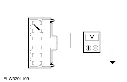
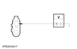
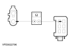
- Check the normally open contact in the closed position.
- Measure the resistance at the socket connections between pin 3 and pin 5.
- Does the relay switch (audible click) when battery voltage is applied and is the resistance less than 5 Ohm? If yes, then the relay is OK. Of no, renew the relay.
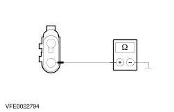
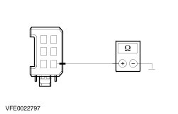
Air conditioning relay - Check the normally open contact in the open position.
- Measure the resistance between pin 3 and pin 5.
- Is the resistance more than 10000 Ohm? If yes, go to 2. If no, renew the air conditioning relay.
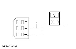
- Check the normally open contact in the closed position.
- Measure the resistance at the socket connection between pin 3 and pin 5.
- Does the relay switch (audible click) when battery voltage is applied and is the resistance less than 5 Ohm? If yes, then the relay is OK. If not, renew the relay.
Fan motor relay (high speed) - Check the normally open contact in the open position.
- Measure the resistance between pin 3 and pin 5.
- Is the resistance more than 10000 Ohm? If yes, go to 2. If no, renew the fan motor relay (high speed).
- Check the normally open contact in the closed position.
- Measure the resistance at the socket connection between pin 3 and pin 5.
- Does the relay switch (audible click) when battery voltage is applied and is the resistance less than 5 Ohm? If yes, then the relay is OK. Of no, renew the relay.
Refrigerant Circuit Workshop Equipment Servicing unit/pressure gauges Stopwatch Electronic leak tester Leak test Test all components and refrigerant lines with an electronic leak tester. Follow the equipment manufacturer's instructions. If necessary switch on the motor and the air conditioning to locate any small leaks in the high-pressure lines. NOTE:Heavy oil contamination on lines or components is an indication of leaks. Leaks If a leakage is detected: eliminate the leak, renew any faulty components and drain and refill the air conditioning system. Pinpoint Test Three values are used for the fault diagnosis: - Low-pressure
- High-pressure
- Compressor switching cycles (on/off)
Connecting the testing equipment The following requirements must be met in order to carry out an accurate test: - Close both of the manual valves on the pressure gauges. Connect the pressure gauges to the high-pressure and the low-pressure side of the air conditioning system.
- Start the engine, set the air conditioning to maximum cooling and air recirculation, and set the blower to maximum power.
- Run the engine at 1500 rev/min.
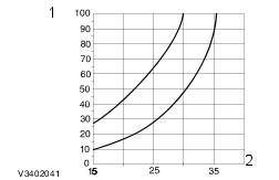
Specified values for high and low-pressure The measured values for high and low-pressure depend on the outside temperature. This is shown in the diagram and the table. The area between the two curves corresponds to the tolerance range. The measured value must lie in this range. Specified values for high-pressure 2 - Outside temperature (°C) Specified values for low-temperature 2 - Outside temperature (°C) Required values: switching cycles The following three diagrams show the required values for the compressor switching cycles. Measure the cycles using a stopwatch and make a note of the result. If the measured values are outside the tolerance range in any of the diagrams then a fault is present. Refer to the Symptom Chart in this section. NOTE:The total cycle time is obtained by adding the on-time to the off-time. Specified values for on-time 2 - Outside temperature (°C) Specified values for off-time 2 - Outside temperature (°C) Specified values for total cycle time 2 - Outside temperature (°C) Check the on/off-cycles The following conditions must be met before checking the switching cycle: - Connect the pressure gauges to the high and low-pressure side of the air conditioning system.
- Start the engine end allow it to run for approx. 10 min at 1500 rev/min.
- Set the air conditioning to maximum cooling and air recirculation.
- Set the blower to maximum power.
- Adjust the interior temperature to approx. 22 °C.
- Measure the switching cycles using a stopwatch and make a note of the results.
- Read off the pressure from the pressure gauges, make a note of the values and compare them with the required values in the diagrams.
As an example, after comparison with the diagrams the following five faults could be present. Next compare these statements with those in the Symptom Chart on the next page and read off the cause of the fault. Example: - High-pressure - too low
- Low-pressure - normal
- Switching cycles per minute - too many
- Clutch on-time - too short
- Clutch off-time - too short
Fault present: not enough refrigerant in the system. Symptom Chart - Refrigerant Circuit | High- pressure | Low- pressure | Clutch cycle times: cycle | Clutch cycle times: on-time | Clutch cycle times: off-time | Fault cause/action | | too high | too high | compressor running constantly | compressor running constantly | compressor running constantly | Condenser contaminated | | too high | normal to too high | compressor running constantly | compressor running constantly | compressor running constantly | Engine overheated | | normal to too high | normal | compressor running constantly | compressor running constantly | compressor running constantly | Air or contaminants in the circuit. Too much refrigerant in the system. | | normal | too high | compressor running constantly | compressor running constantly | compressor running constantly | Fixed orifice tube, O-rings damaged or leaking | | normal | normal | too slow | too long or constantly | normal or not at all | Contaminants in the circuit or too much refrigerant oil | | normal | too low | too slow | too long | too long | Low-pressure switch faulty | | normal to too low | too high | compressor running constantly | compressor running constantly | compressor running constantly | Compressor faulty | | normal to too low | normal to too high | compressor running constantly | compressor running constantly | compressor running constantly | Low-pressure line blocked | | normal to too low | normal | too fast | too short | normal | Evaporator blocked | | normal to too low | normal | too fast | too short | normal to too long | Condenser, fixed orifice tube or high-pressure line blocked | | normal to too low | normal | too fast | too short | too short | Not enough refrigerant in the system | | normal to too low | normal | too fast | too short | too long | Evaporator input line blocked | | normal to too low | too low | compressor running constantly | compressor running constantly | compressor running constantly | Low-pressure line | | - | - | irregular operation or inoperative | irregular operation or inoperative | irregular operation or inoperative | Low-pressure switch contacts dirty or permanently open. Connector of low-pressure switch or of compressor clutch dirty or damaged. | |