
Ranger 2WD L4-153 2.5L SOHC VIN C SFI (1998)
1. Place the Anglemaster II Driveline Inclinometer on the starter or other suitable surface parallel to the floor. Record and verify the angle is within
specification.
-
If it is out of specification, inspect the engine mounts.
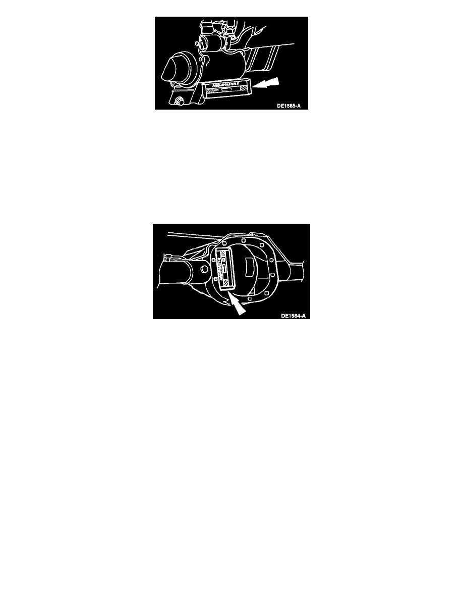
Pinion Angle Inspection
CAUTION: Prior to checking driveline angularity, inspect the U-joints for proper operation.
1. Raise and support the vehicle.
-
Normalize the suspension.
NOTE: Use a drive-on hoist or back onto a front end alignment rack.
2. Place the Anglemaster II Driveline Inclinometer vertical so it is flush against two axle housing cover bolts.
3. Record the pinion angle. If the angle is out of specification, inspect the rear suspension mounting.
Driveline Vibration
An analysis of driveline vibration can also be conducted using the Electronic Vibration Analyzer; follow the manufacturer's directions.
Driveline vibration exhibits a higher frequency and lower amplitude than does high-speed shake. Driveline vibration is directly related to the speed of
the vehicle and is usually noticed at various speed ranges.
Driveline vibration can be perceived as a tremor in the floorpan or is heard as a rumble, hum, or boom. Driveline vibration can exist in all drive
modes, but may exhibit different symptoms depending upon whether the vehicle is accelerating, decelerating, floating, or coasting. Check the driveline
angles if the vibration is particularly noticeable during acceleration or deceleration, especially at lower speeds. Driveline vibration can be duplicated
by supporting the axle upon a hoist or upon jack stands, though the brakes may need to be applied lightly in order to simulate road resistance.
1. Raise the vehicle promptly after road testing. Use a twin-post hoist or jack stands to prevent tire flat-spotting. Engage the drivetrain and accelerate
to the observed road test speed to verify the presence of the vibration. If the vibration is not evident, check the non-driving wheels with a wheel
balancer to rule out imbalance as a possible cause. If required, balance the non-driving wheels and repeat the road test. If the vibration is still
evident, proceed to Step 2.
2. Mark the relative position of the drive wheels to the wheel lugs. Remove the wheels. Install all the lug nuts in the reversed position and repeat the
road speed acceleration. If the vibration is gone, refer to the tire and wheel runout procedure. If the vibration persists, proceed to Step 3.
3. Inspect the driveshaft(s) for signs of physical damage, missing balance weight, undercoating, improper seating, wear and binding universal joints.
Clean the driveshaft and replace the universal joints or replace the driveshaft if damaged. Check the index marks (paint spots) on the rear of the
driveshaft and axle companion flange. If these marks are more than one-quarter turn apart, disconnect the driveshaft and re-index to align the
marks as closely as possible. After any corrections are made, recheck for vibration at the road test speed. If the vibration is gone, reinstall the
wheels and road test. If the vibration persists, proceed to Step 4.