
Ranger 2WD L4-2.3L (2009)
Removal
1. Disconnect the battery ground cable.
2. Remove the intake manifold assembly. For additional information, refer to Intake Manifold See: Intake Manifold/Service and Repair.
3. Position aside the Cylinder Head Temperature (CHT) sensor cover.
4. Disconnect the CHT sensor electrical connector.
5. Disconnect the engine wiring harness support bracket retainers from the valve cover studs.
6. Disconnect the spark plug wires from the spark plugs.
7. Disconnect the ignition coil electrical connector.
8. Remove the 4 bolts and the ignition coil and spark plug wires as an assembly.
9. Disconnect the Camshaft Position (CMP) sensor electrical connector.
10. Remove the bolt and the CMP sensor.
11. Disconnect the crankcase ventilation tube quick connect coupling.
12. Remove the 10 bolts, the 4 stud bolts and the valve cover.
13. NOTICE: Do not use metal scrapers, wire brushes, power abrasive discs or other abrasive means to clean the sealing surfaces. These tools
cause scratches and gouges which make leak paths.
Clean and inspect the cylinder head sealing surfaces with metal surface prep and silicone gasket remover. Observe all warnings and cautions and
follow all application directions contained on the packaging of the silicone gasket remover and metal surface prep.
14. Remove and discard the 4 valve cover gaskets.
Installation
1. Install 4 new valve cover gaskets.
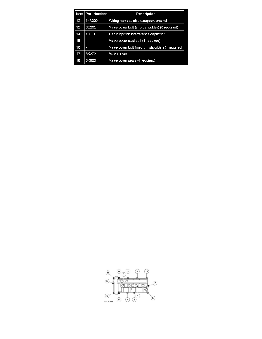
2. Position the valve cover and install the 10 bolts and 4 stud bolts in the sequence shown.
-
Tighten to 10 Nm (89 lb-in).
3. Connect the crankcase ventilation tube quick connect coupling.
4. NOTE: Apply clean engine oil to the O-ring seal prior to installation.