
Ranger 2WD V6-171 2.8L (1983)
Vacuum Brake Booster: Service and Repair
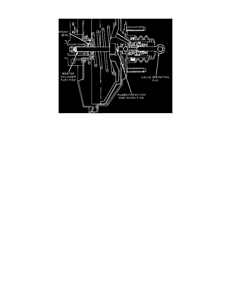
Fig. 17 Checking reaction disc installation
Make sure booster rubber reaction disc is properly installed as shown in Fig. 12, if the master cylinder pushrod is removed or accidentally pulled out. A
dislodged disc may cause excessive pedal travel and extreme operation sensitivity. The disc is black compared to the silver colored valve plunger that
will be exposed after pushrod and front seal are removed. The booster unit is serviced as an assembly and must be replaced if the reaction disc cannot be
properly installed and aligned, or if it cannot be located within the unit itself.
1.
Disconnect stop light switch wiring, support master cylinder from underside, and remove master cylinder to booster retaining nuts.
2.
Loosen clamp which secures manifold vacuum hose to booster check valve and remove hose, then remove booster check valve.
3.
Pull master cylinder off booster and support far enough away to allow removal of booster assembly.
4.
On models equipped with pushrod mounted stop light switch, remove retaining pin, then slide stop light switch, pushrod, spacer and bushing off
brake pedal arm.
5.
On all models, remove brake booster attaching bolts and the booster.
6.
Reverse procedure to install, then start engine and check brake operation.