
Ranger 2WD V6-4.0L (2010)
GO to I19.
-------------------------------------------------
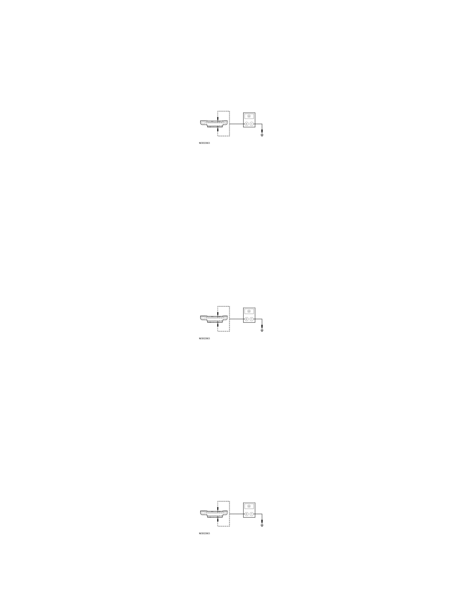
I19 CHECK THE HS-CAN (+) AND HS-CAN (-) CIRCUITS FOR A SHORT TO GROUND WITH THE ABS Module DISCONNECTED
-
Disconnect: SJB C135.
-
Measure the resistance between the DLC C251-6, circuit VDB04 (WH/BU), harness side and ground; and between the DLC C251-14, circuit
VDB05 (WH), harness side and ground.
-
Are the resistances greater than 1,000 ohms?
Yes
CONNECT the negative battery cable. GO to I26.
No
GO to I20.
-------------------------------------------------
I20 CHECK THE HS-CAN (+) AND HS-CAN (-) CIRCUITS FOR A SHORT TO GROUND WITH THE SJB DISCONNECTED
-
Disconnect: RCM C2280d.
-
Measure the resistance between the DLC C251-6, circuit VDB04 (WH/BU), harness side and ground; and between the DLC C251-14, circuit
VDB05 (WH), harness side and ground.
-
Are the resistances greater than 1,000 ohms?
Yes
CONNECT the negative battery cable. GO to I27.
No
GO to I21.
-------------------------------------------------
I21 CHECK THE HS-CAN (+) AND HS-CAN (-) CIRCUITS FOR A SHORT TO GROUND WITH THE RCM DISCONNECTED
-
Disconnect: RCM C2041a.
-
Measure the resistance between the DLC C251-6, circuit VDB04 (WH/BU), harness side and ground; and between the DLC C251-14, circuit
VDB05 (WH), harness side and ground.
-
Are the resistances greater than 1,000 ohms?
Yes