
Ranger 2WD V6-4.0L (2010)
-
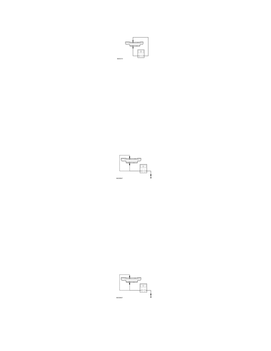
Disconnect: Audio Unit (ACM) C290c.
-
Measure the resistance between the DLC C251-3, circuit VDB06 (GY/OG), harness side and the DLC C251-11, circuit VDB07 (VT/OG), harness
side.
-
Is the resistance less than 5 ohms?
Yes
REPAIR the circuit. CONNECT all modules. CONNECT the negative battery cable. CLEAR the DTCs. REPEAT the network test with the scan tool.
No
CONNECT the negative battery cable. GO to J16.
-------------------------------------------------
J12 CHECK THE MS-CAN (+) AND MS-CAN (-) CIRCUITS FOR A SHORT TO GROUND WITH THE SDARS MODULE
DISCONNECTED
-
Disconnect: SDARS Module C2358.
-
Measure the resistance between the DLC C251-3, circuit VDB06 (GY/OG), harness side and ground; and between the DLC C251-11, circuit
VDB07 (VT/OG), harness side and ground.
-
Are the resistances greater than 5,000 ohms?
Yes
CONNECT the negative battery cable. GO to J15.
No
GO to J13.
-------------------------------------------------
J13 CHECK THE MS-CAN (+) AND MS-CAN (-) CIRCUITS FOR A SHORT TO GROUND WITH THE AUDIO UNIT (ACM)
DISCONNECTED
-
Disconnect: Audio Unit (ACM) C290c.
-
Measure the resistance between the DLC C251-3, circuit VDB06 (GY/OG), harness side and ground; and between the DLC C251-11, circuit
VDB07 (VT/OG), harness side and ground.
-
Are the resistances greater than 5,000 ohms?
Yes
CONNECT the negative battery cable. GO to J16.
No