
Ranger 2WD V6-4.0L (2010)
1. Depower the SRS. For additional information, refer to Supplemental Restraint System (SRS) Depowering and Repowering See: Air Bag(s)
Arming and Disarming/Service and Repair/Supplemental Restraint System (SRS) Depowering and Repowering.
2. Remove the driver air bag module. For additional information, refer to Driver Air Bag Module See: Air Bag/Service and Repair/Driver Air Bag
Module.
3. NOTE: Make sure the wheels are in the straight-ahead position.
Remove the steering wheel.
4. Remove the ignition lock cylinder. For additional information, refer to Doors, Hood and Trunk &/or Locks.
5. Remove the 2 screws and position the hood release handle aside.
6. Remove the 2 screws from the steering column opening trim panel, pull out to release the clips and remove the lower steering column opening
finish panel.
7. Remove the 5 bolts and steering column opening cover reinforcement.
8. If equipped, remove the tilt release lever/handle.
9. Remove the 3 screws and lower steering column shroud.
10. Position the upper steering column shroud up enough to access the clockspring clips.
11. Detach the clockspring wire harness from the wiring retainer.
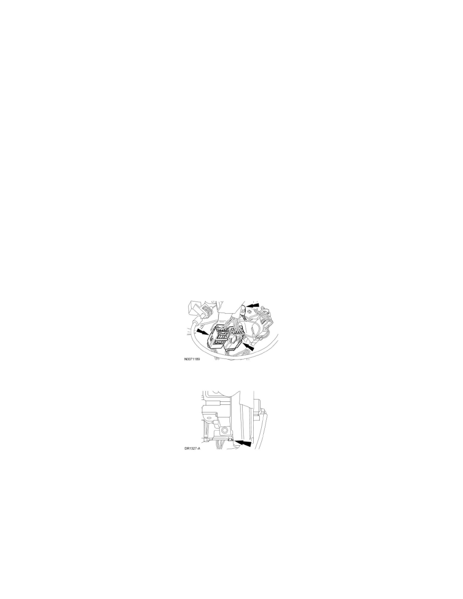
12. Disconnect the clockspring electrical connectors.
-
Disconnect the harness ground wire.
-
Release the pin-type retainers and disconnect the clockspring electrical connectors.
13. Release the lower clockspring clip.
14. Remove the screw, the Passive Anti-Theft System (PATS) antenna and the key-in-ignition warning indicator switch from the lock cylinder
housing.