
Ranger 2WD V6-4.0L (2010)
System failure may occur if PMI is not performed. For additional information, refer to Information Bus. See: Powertrain Management/Computers and
Control Systems/Information Bus/Service and Repair
NOTE: The air bag warning indicator illuminates when the correct RCM fuse is removed and the ignition is ON.
NOTE: The Supplemental Restraint System (SRS) must be fully operational and free of faults before releasing the vehicle to the customer.
1. When installing a new RCM, carry out the steps necessary for the Programmable Module Installation (PMI) procedure. For additional information,
refer to Information Bus. See: Powertrain Management/Computers and Control Systems/Information Bus/Service and Repair
2. Depower the SRS. For additional information, refer to Supplemental Restraint System (SRS) Depowering and Repowering See: Air Bag
Systems/Air Bag(s) Arming and Disarming/Service and Repair/Supplemental Restraint System (SRS) Depowering and Repowering in the General
Procedures.
3. If equipped, remove the floor console. For additional information, refer to Instrument Cluster / Carrier &/or Interior Moulding / Trim.
4. If equipped, remove the consolette tray.
-
Remove the consolette tray mat.
-
Remove the 4 screws and consolette tray.
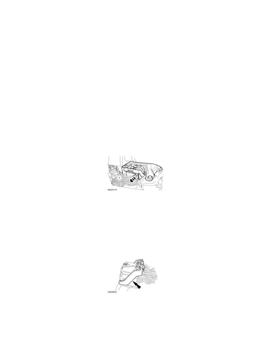
5. Disconnect the small RCM electrical connector.
6. Disconnect the large RCM electrical connector.
1. Pinch the thumb tab and pivot the connector position assurance lever all the way back until it stops.
2. Pull out and disconnect the RCM electrical connector.
7. Remove the 3 bolts and RCM.
Installation
1. WARNING: Always tighten the fasteners of the restraints control module (RCM) and impact sensor (if equipped) to the specified torque.
Failure to do so may result in incorrect restraint system operation, which increases the risk of personal injury or death in a crash.
Install the RCM and 3 bolts.
-
To install, tighten to 12 Nm (106 lb-in).
2. Make sure the large RCM connector position assurance lever is in the full release position before attempting to connect the connector.
3. NOTICE: Putting the large Restraints Control Module (RCM) electrical wiring connector into the RCM on an angle can cause bad
electrical connections and damage components.
Position the large RCM electrical connector into the RCM.
-
NOTICE: Do not push the connector to the point where the lever pivots and seats itself. Light pressure is needed to get the connector
into position on the Restraints Control Module (RCM), before using the lever to fully seat the connector. Damage to the connector or
component may occur.